
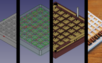
In this article we use the spreadsheet workbench in FreeCAD to make it easy to create a hinge or tenon routing template.
In this article we want to use the Spreadsheet workbench to create a simple jig from four plywood pieces that can be used to route a hinge or a loose tenon.
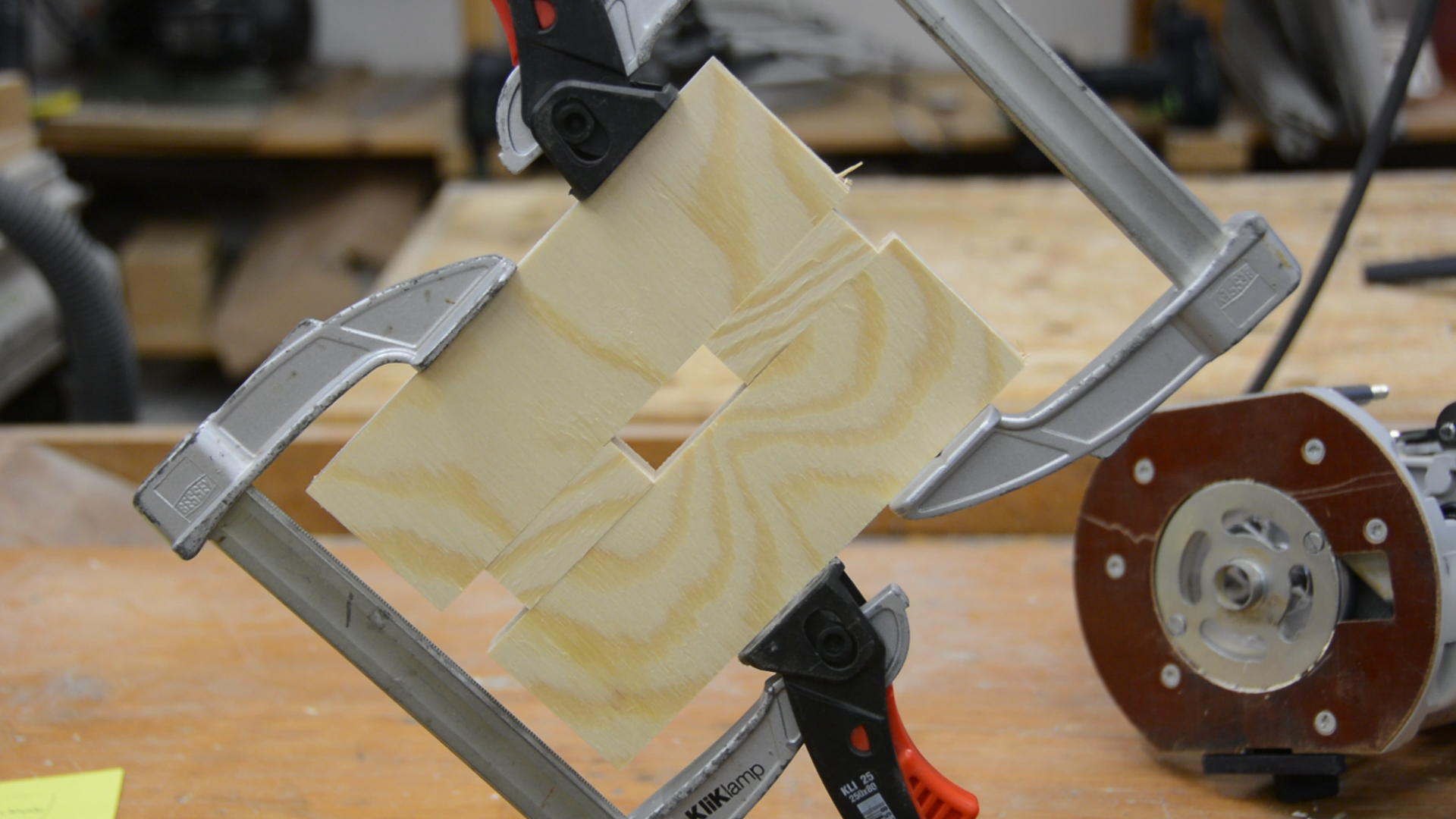
The principle is very simple and we used it for the wooden loose tenon jig. A guide bushing rides in a slot and a router bit is cutting a pocket with a certain recess.

The FreeCAD Spreadsheet workbench
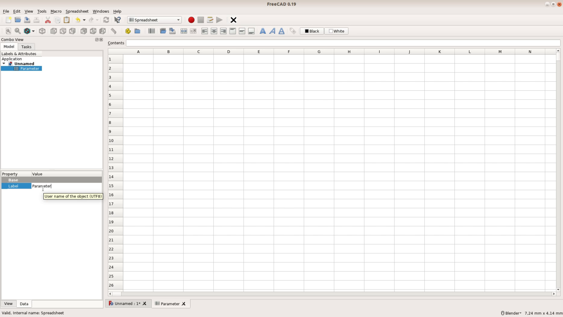
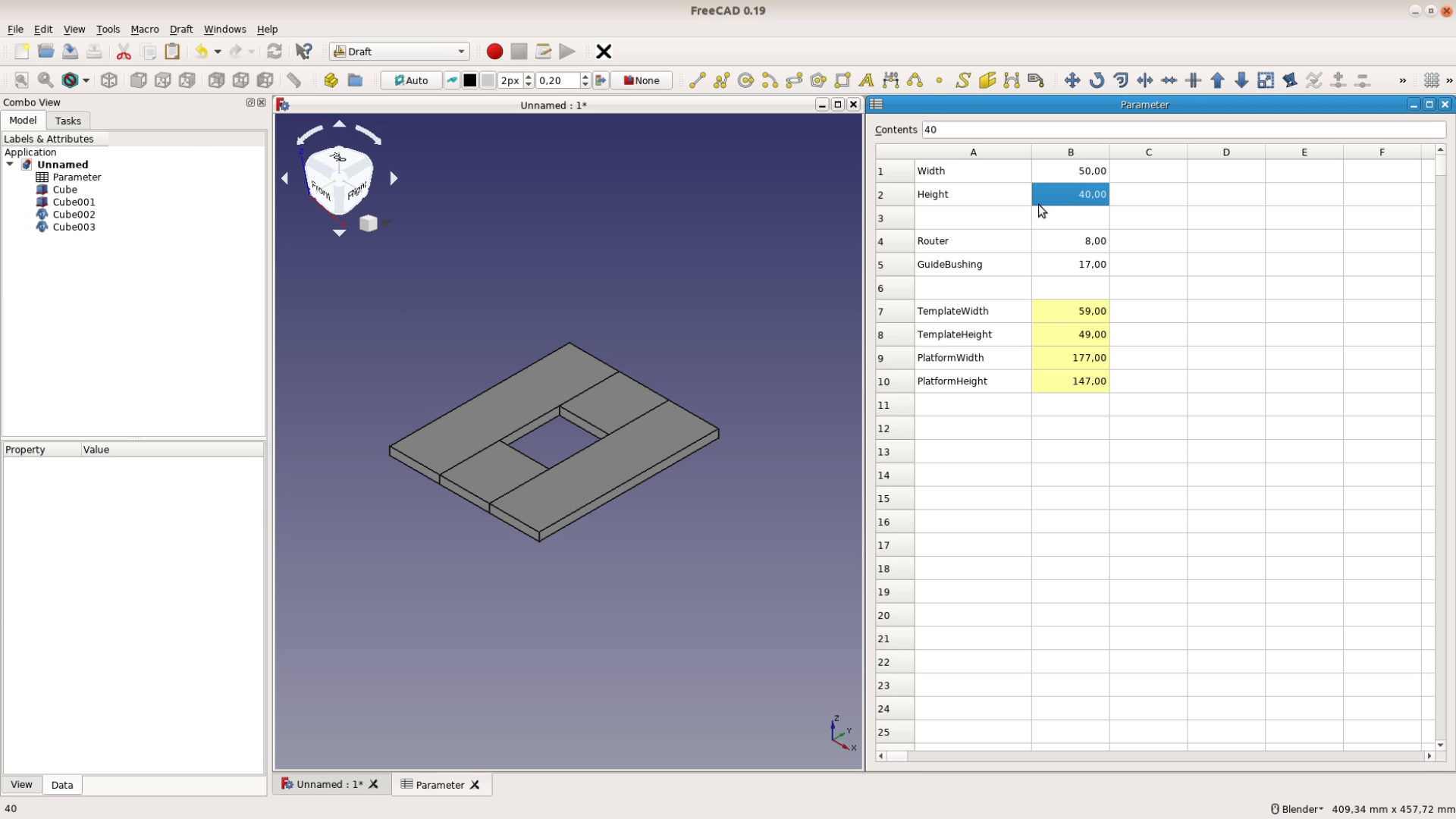
We use FreeCAD version 0.19 and after swiching to the Spreadsheet workbench we create a new Spreadsheet and open it by a double click. We also give it a better name and call it Parameter.
FreeCAD’s spreadsheet workbench is similar to a very simple version of Excel. You can’t use it for complex analysis but creating an overview of the most important parameters is quite easy.
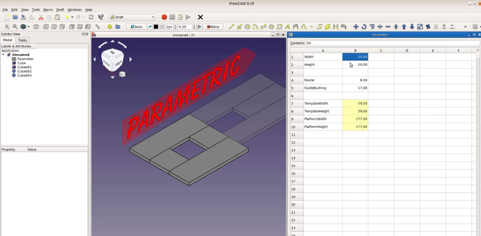
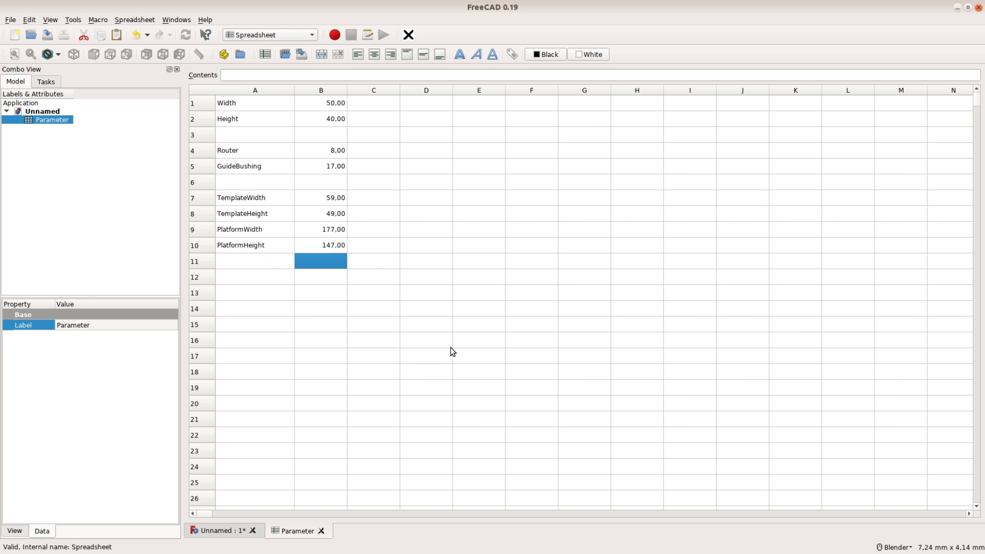
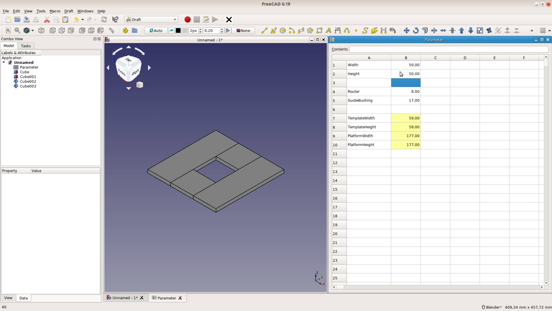
For our example we need the width and height of the pocket we want to create, the size of the router bit and the size of the guide bushing that we are using. In the spreadsheet itself we can calculate the size of the opening. It’s the width of the pocket plus the guide bushing diameter minus the router bit diameter.
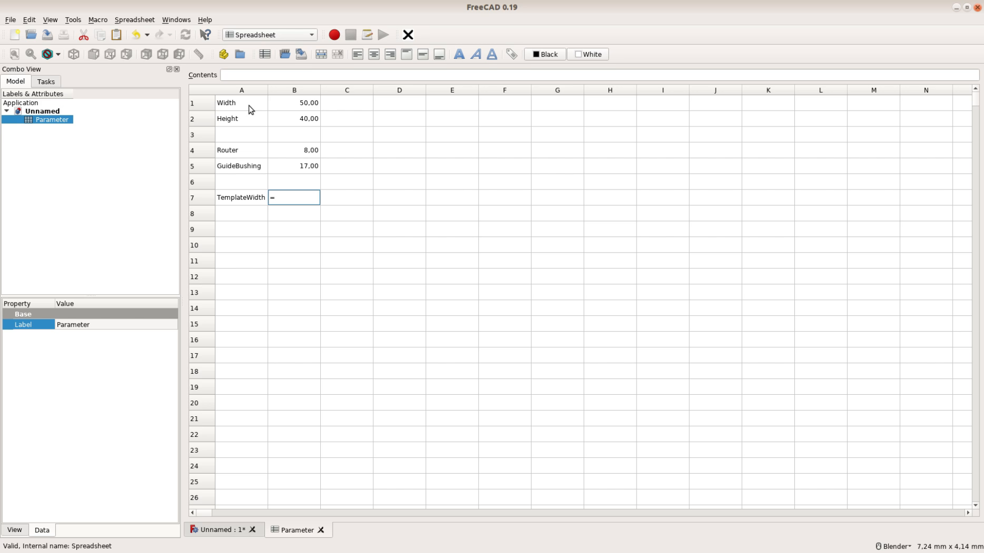

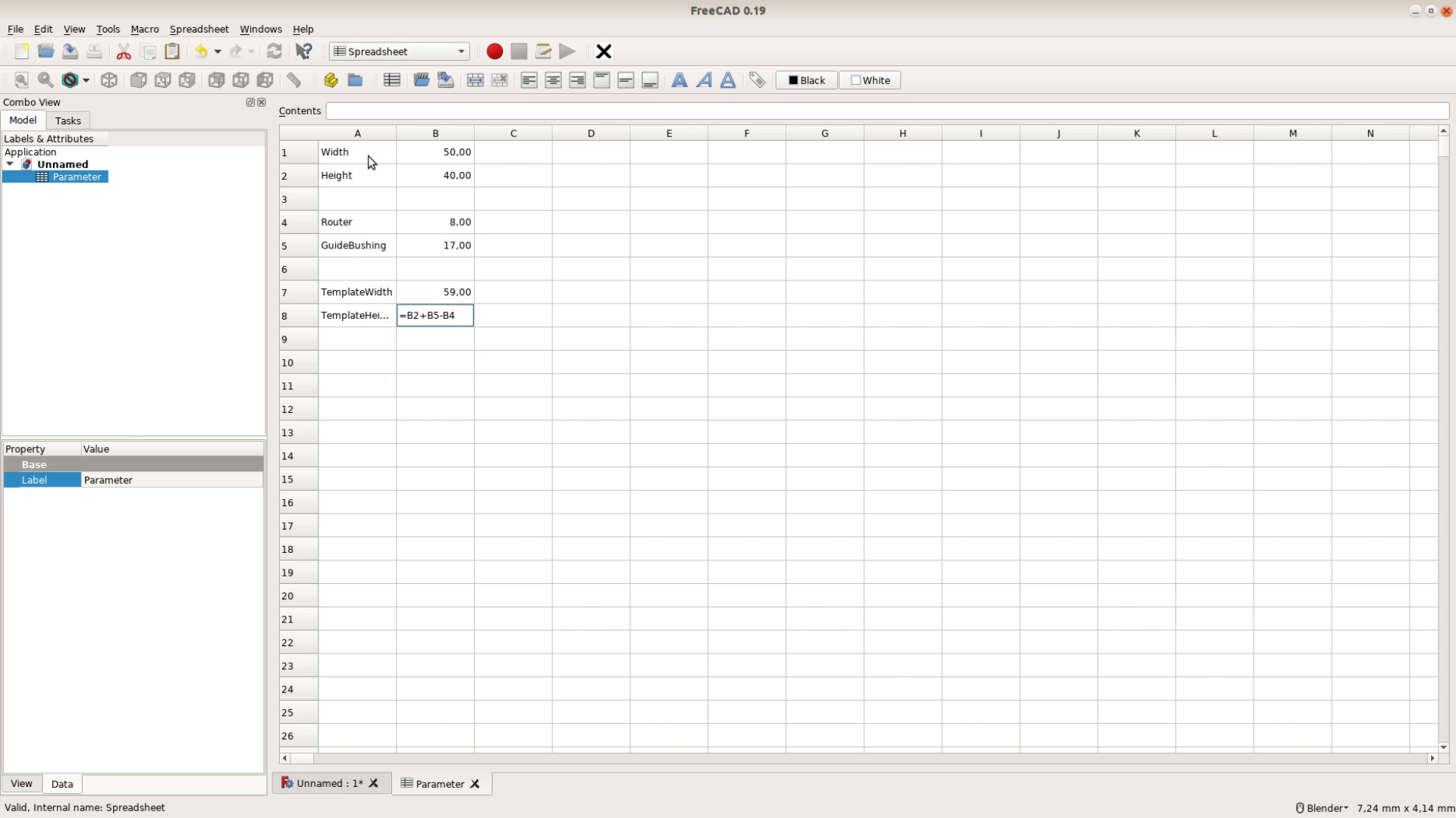
We also create cells for the overall size of the jig and to keep things simple will use three times the width and height.
There are two ways to give a cell a name. For a single cell you can open the Cell properties dialogue and put the name as an Alias for the Cell.

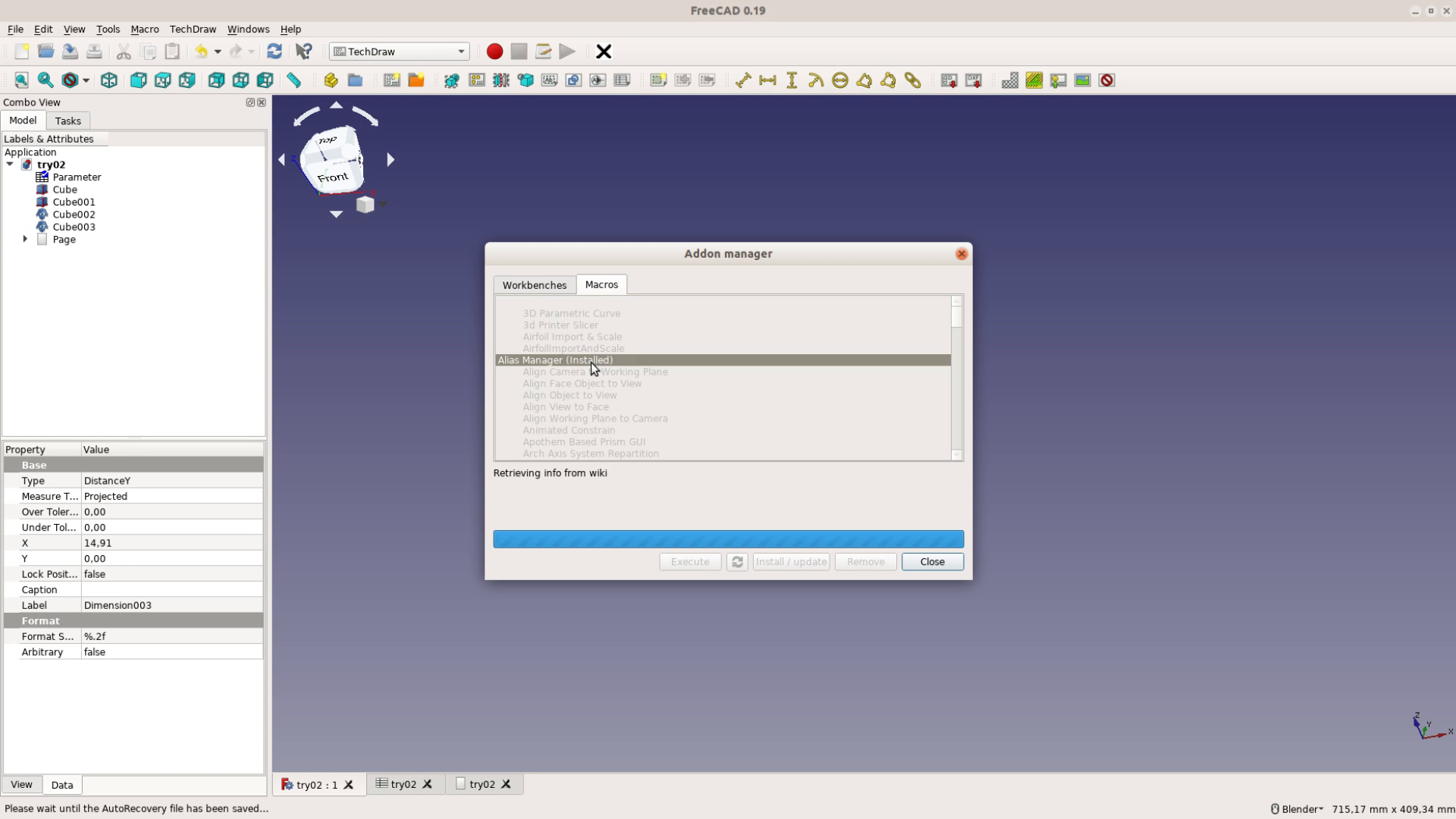
There is a macro that makes this task easier. Go to Tools, Addon Manager, Macros, select the Alias Manager and click install.
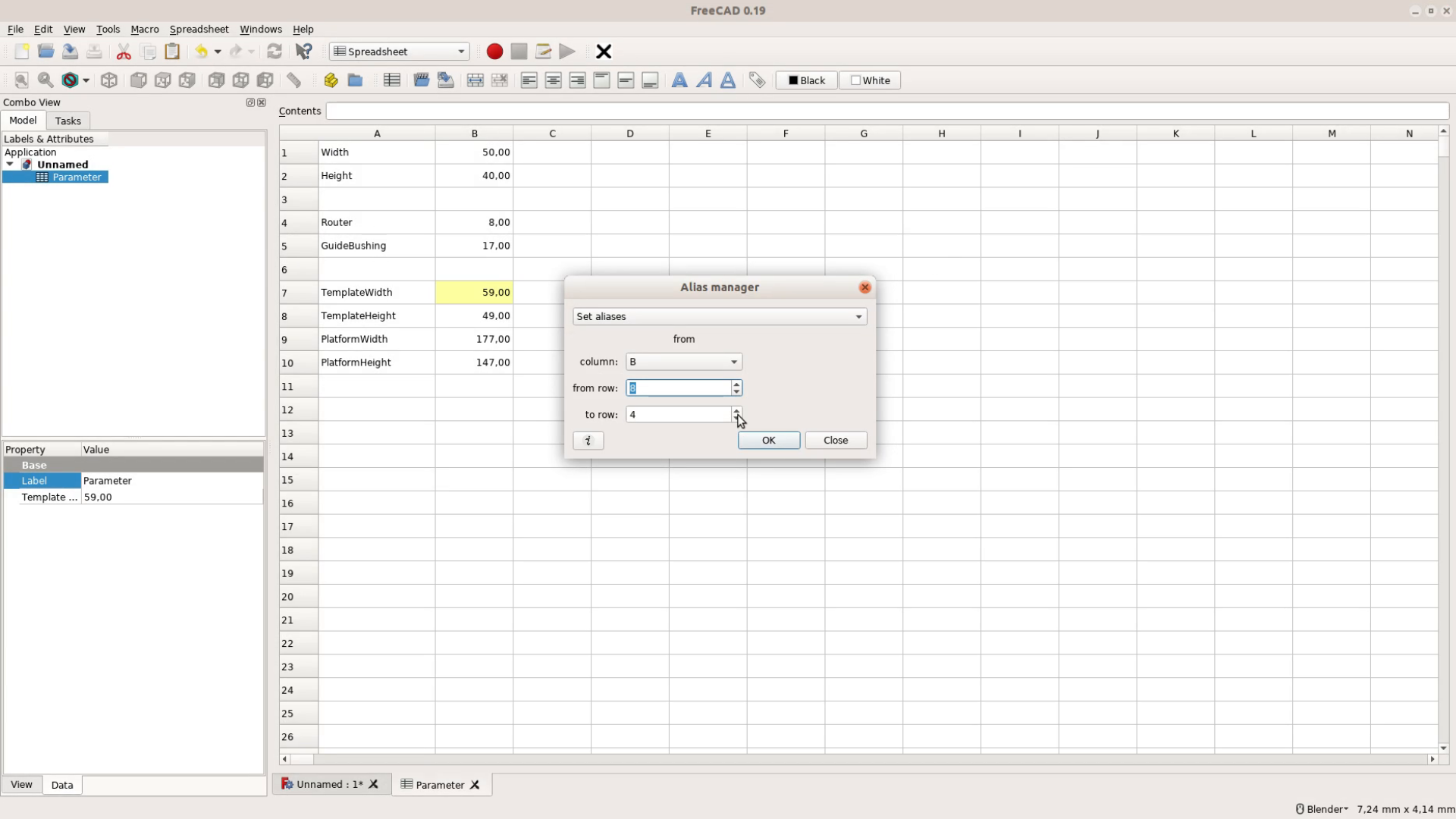
Now you will find the Alias Manager Macro in the Macro tab. You select the starting and the end row and the aliases are automatically set to the names in column A.
Creating the template
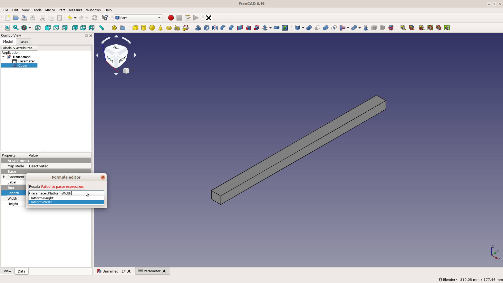
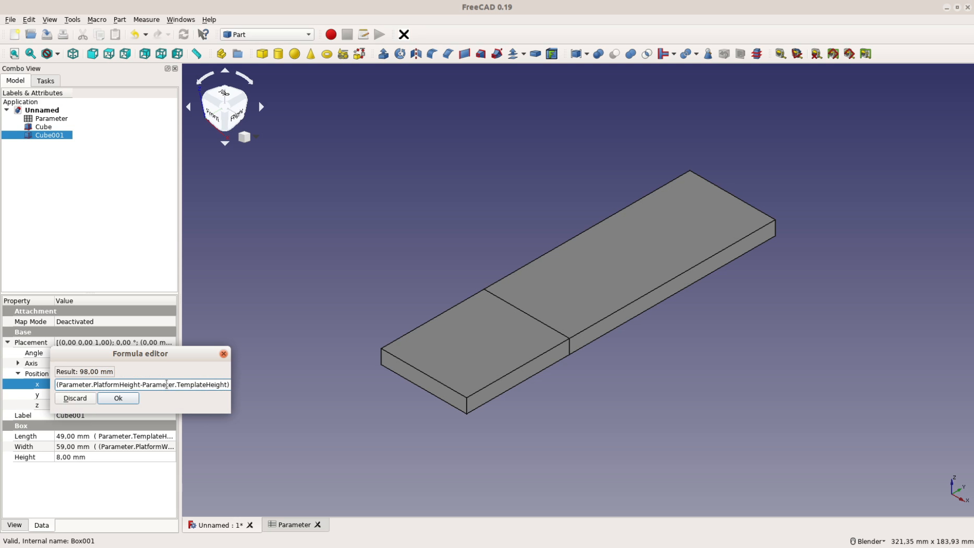
Next we go to the Part workbench and insert a Cube – like we did in the first part of the tutorial. The thickness of the template is 8. For the Width we click on the small circle to enter a formula.
In this case the formula is simple: It is just the value of the PlatformWidth cell in the Parameter Spreadsheet. So we write Parameter dot PlatformWidth.
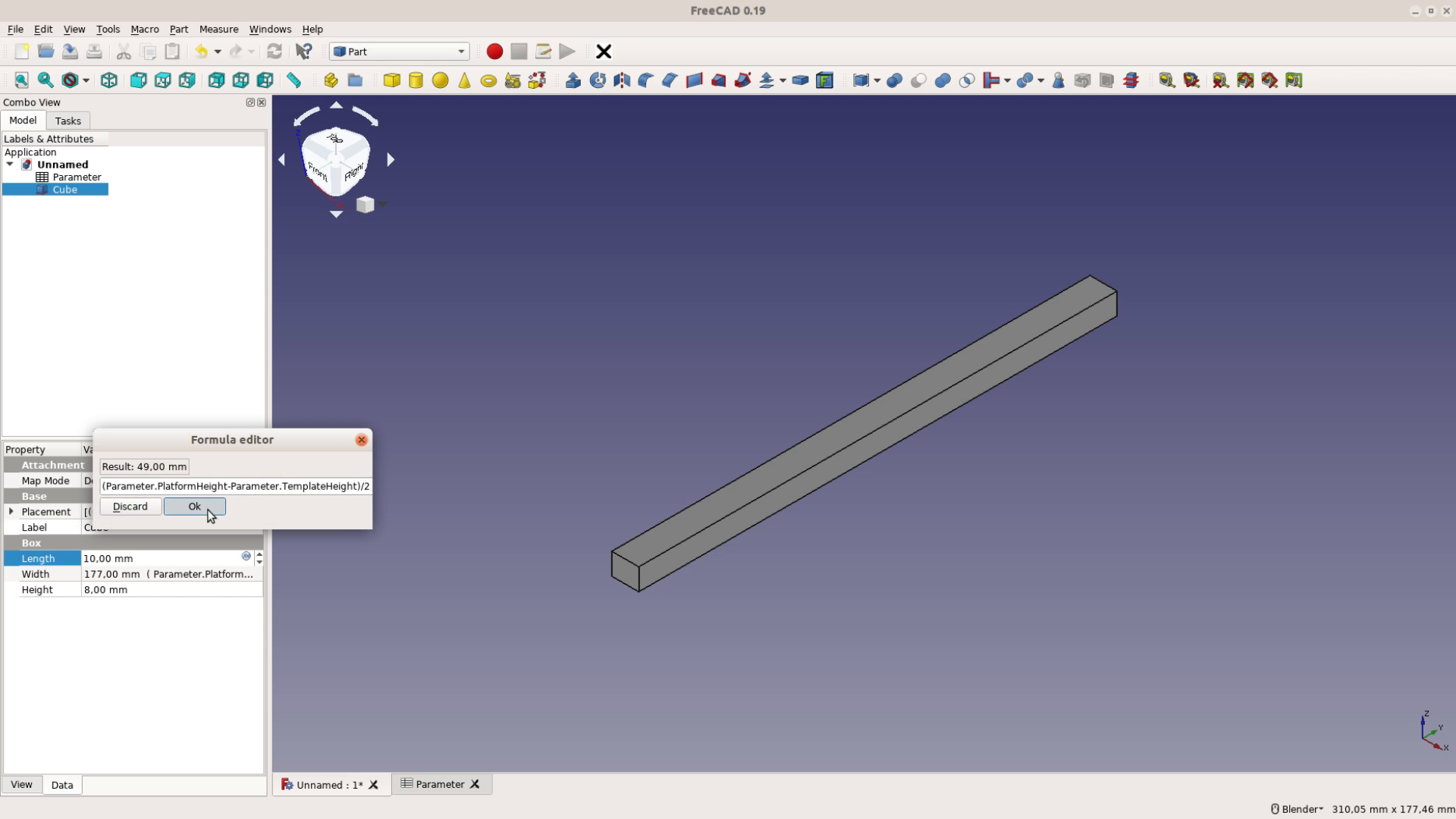
The Height is a bit more complex. It is half of the difference between the entire height of the jig and the height of the slot.
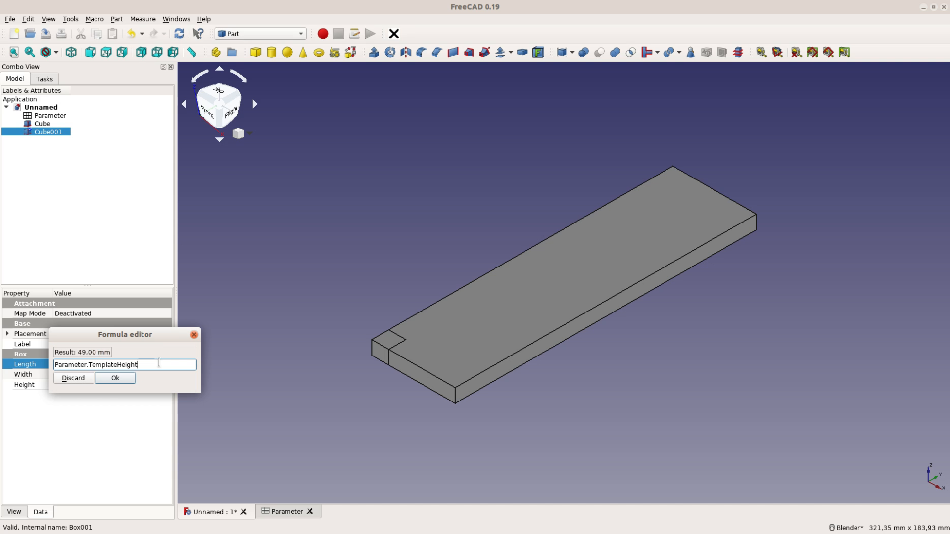
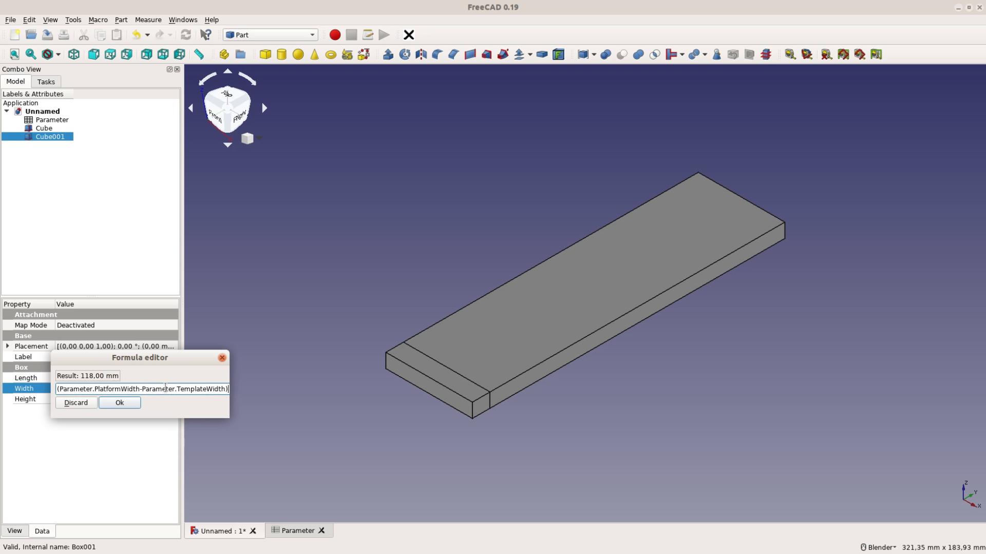
The next cube is going to be the smaller piece of the template. It’s Length is the height of the template and the width is half of the difference between the entire platform width and the width of the template slot.
Next we want to position the smaller piece at the right place. For this we change the Placement, Position, x value of the piece to the same formula that we used for the shorter side of the first piece.
Cloning parts
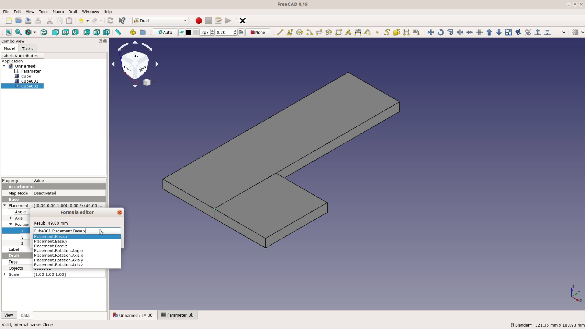
With the two shapes ready we go the Draft workbench and create a clone of our shapes. A clone is a copy of the original object that will change it’s size when the original shape is changed. When a clone is created the x position becomes a static value. For the model to be fully parametric we change the formula and take the x-Position of the original.
For the y position we move the object by its own width and the width of the template slot.

We then repeat the same steps for the long piece. After cloning it we change its x position.
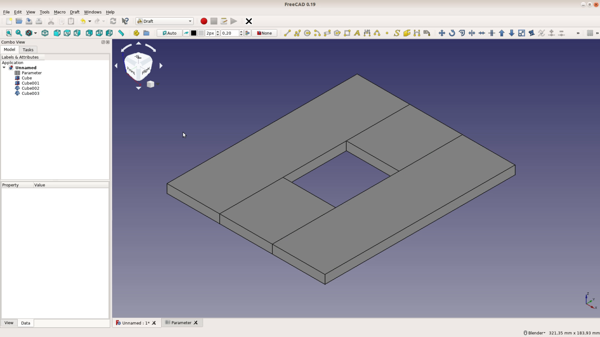
We are done with the model and arrange the window side by side so that we can enjoy the beauty of a fully parametric model. When we change the width and the height of the slot in the FreeCAD Spreadsheet Workbench the model is automatically adjusted.
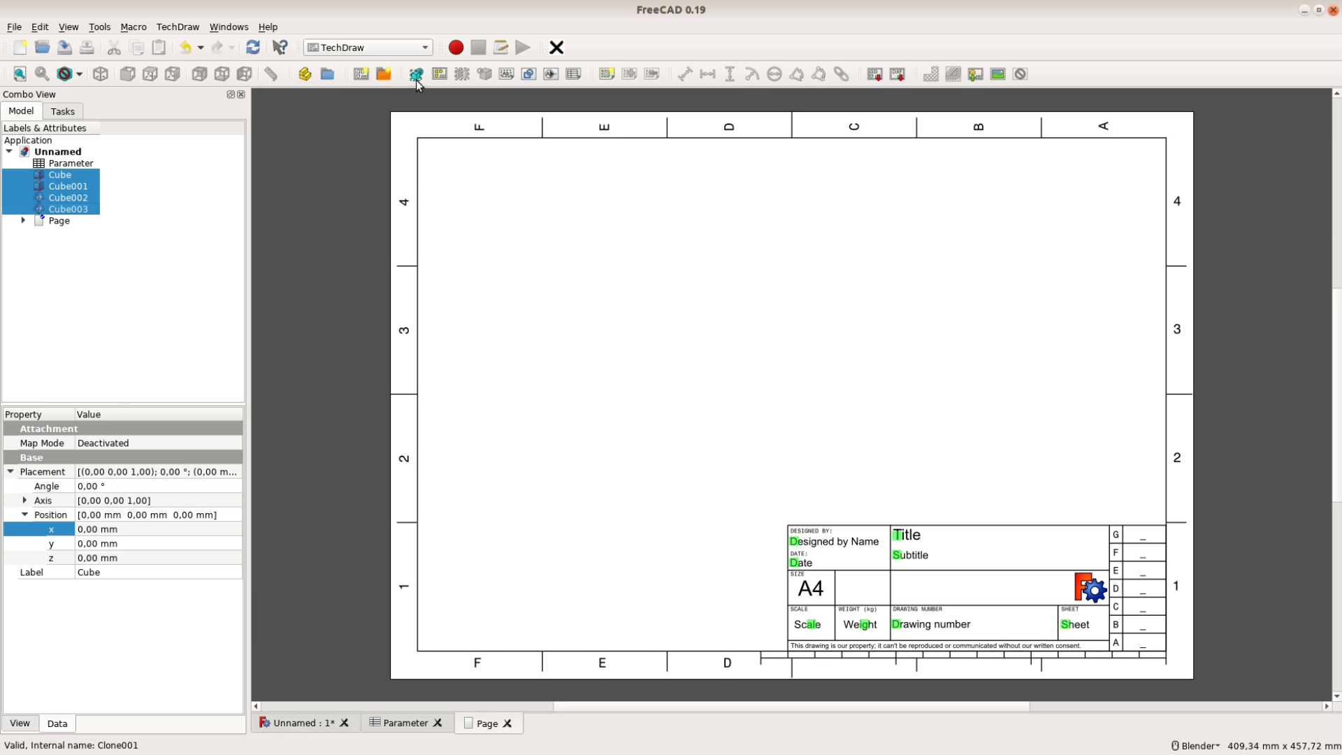
Creating a printout with the TechDraw workbench
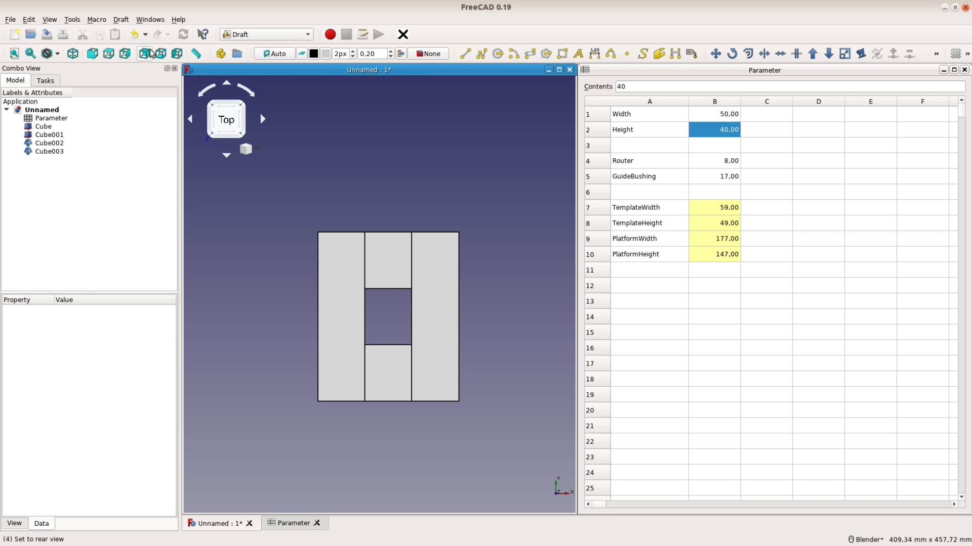
For this model to be of any practical value we need some measures that we can take to the saw and cut the template to size. After making sure we look at the top of the model we switch to the TechDraw workbench and create a new drawing.
With all the objects selected we add a view of these objects. The view gets scaled dow so that it fits on the paper after a quick recomputing of the sheet.
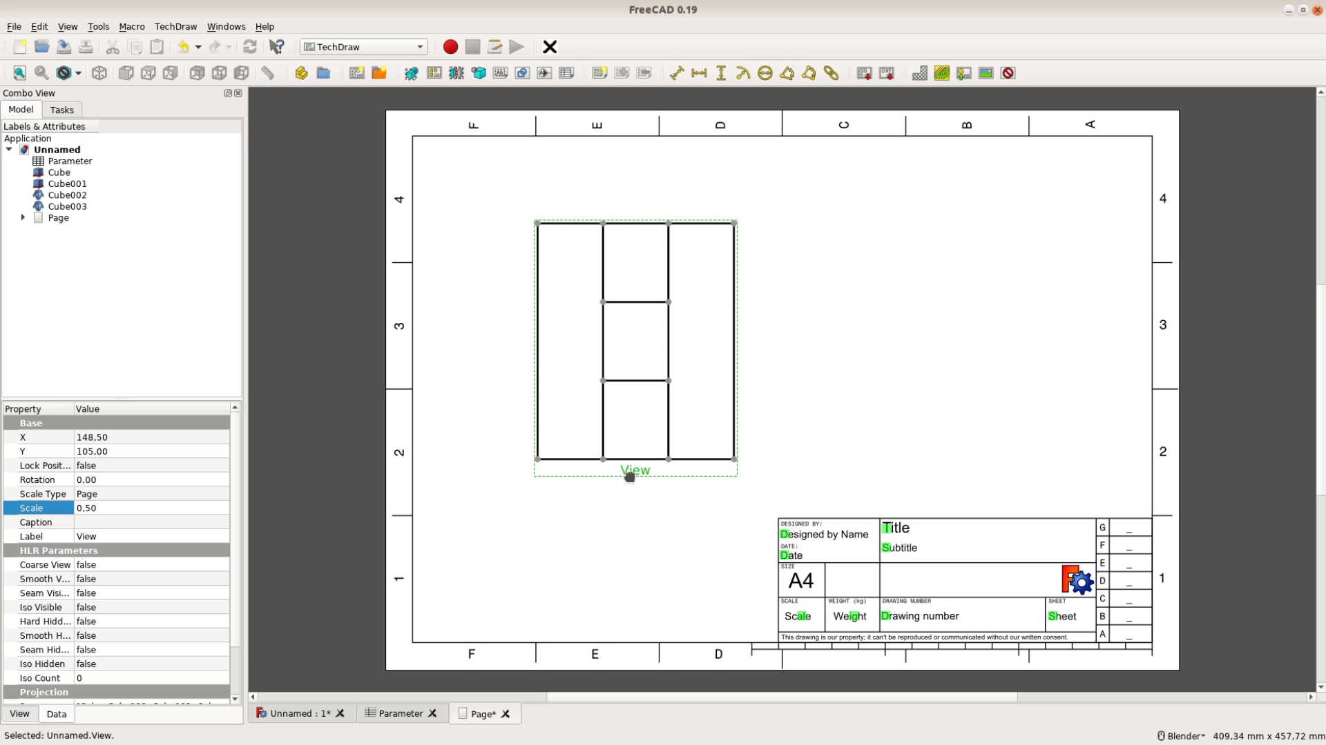
In this drawing we can add horizontal and vertical measure by just selecting two points and adding the respective measurement.
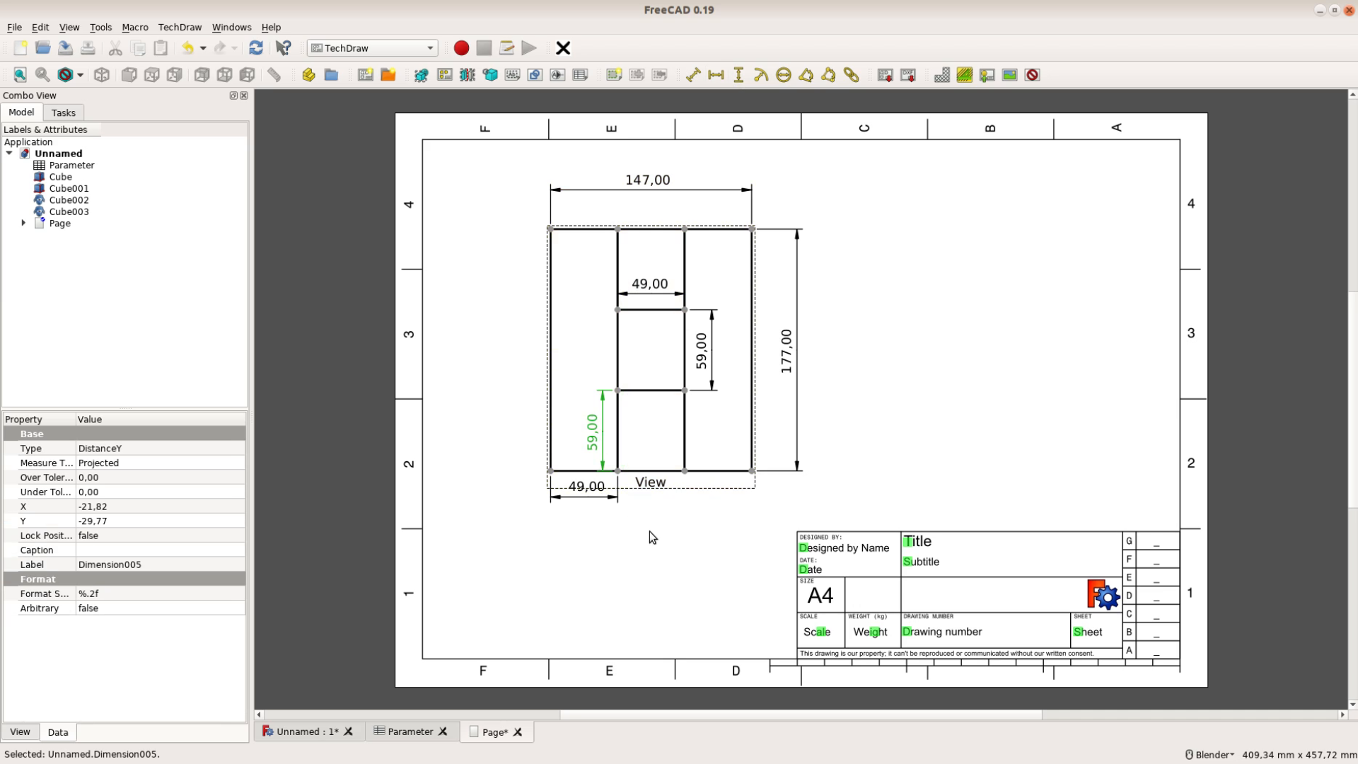
Also this drawing is fully parametric. When we change the values in the spreadsheet the model and the drawing are changing their values.

This was only a sneak preview of the TechDraw workbench – we will get back to it in a later part in more detail.e

i have small problem ,i did everything correctly /All the formula working well recheck and recheck
everything but when i change the width and height in the spreadsheet the pc is not working at all with what i put
freecad woodworkers 03
Did you hit the recalculate button after changing the values?
and where is that calculate button plse plse plse
On this page you can see the Icon for the recalculate: FreeCAD Wiki
thank you for your help but nothing works,i just gave up spreadsheet now cube ,cube001,cube002,cube003 they have no more formula maybe i will retry this one later
FreeCAD can be a bit complicated at first. Maybe focus on another topic first and get back to the spreadsheets later.