
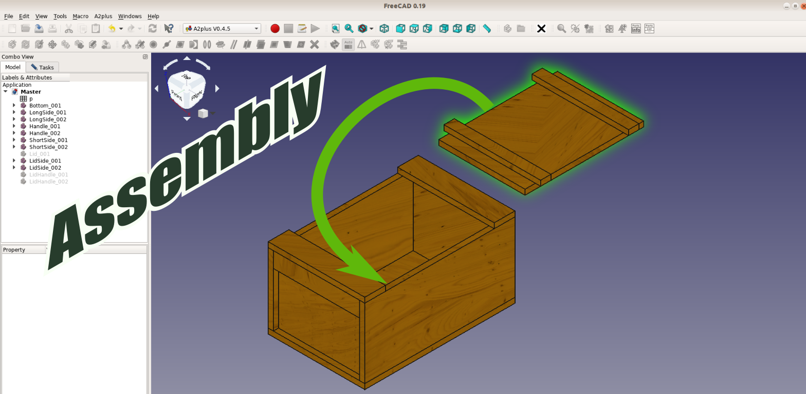
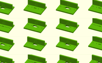
In this tutorial we create step by step an assembly of a Japanese toolbox in FreeCAD.
We have a shorter overview article on this toolbox but in this video we will use FreeCAD version 0.19 and slowly go step by step through the assembly process.
Setting the parameters
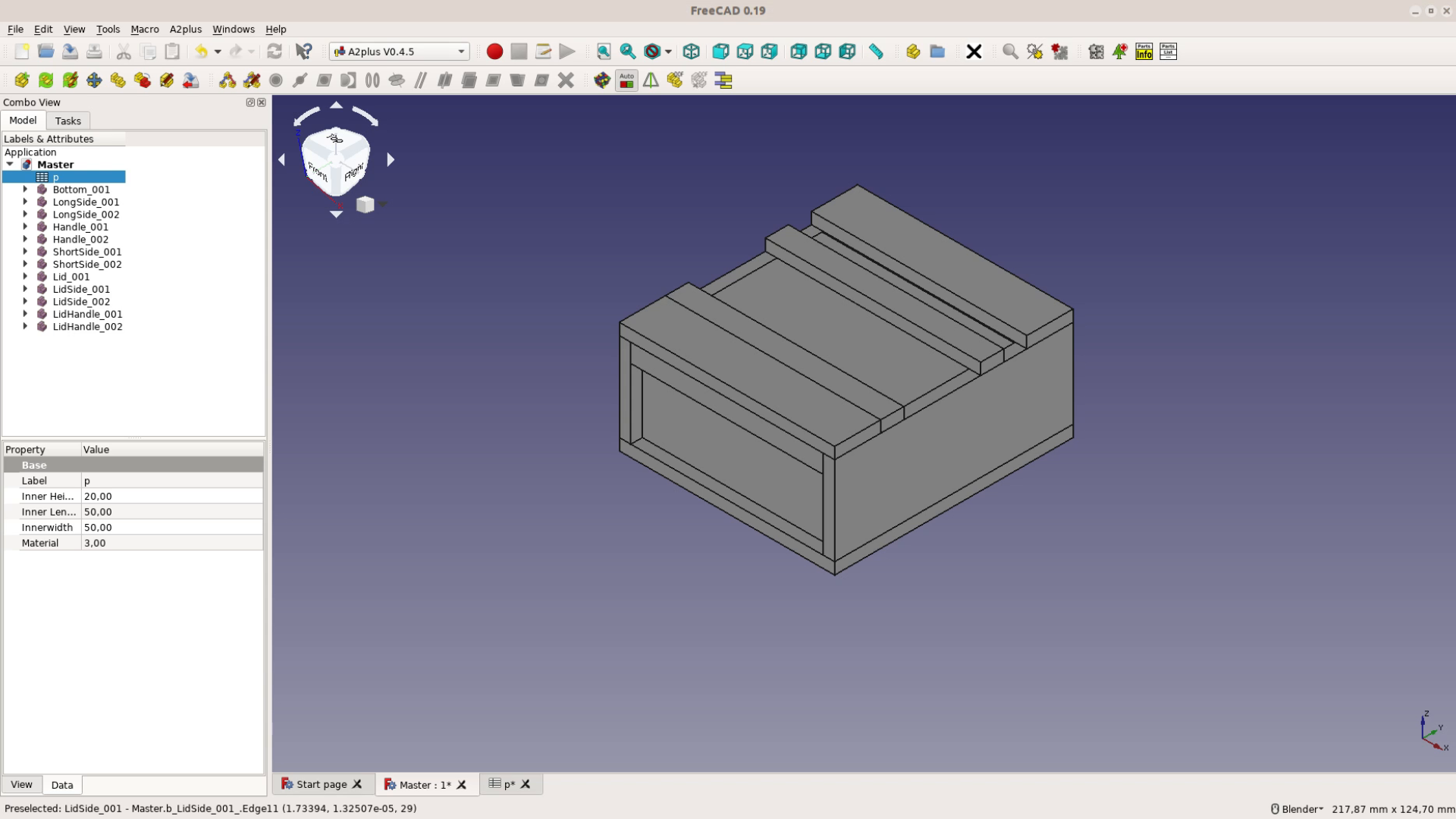
The first step is to create this spreadsheet with all the dimensions.
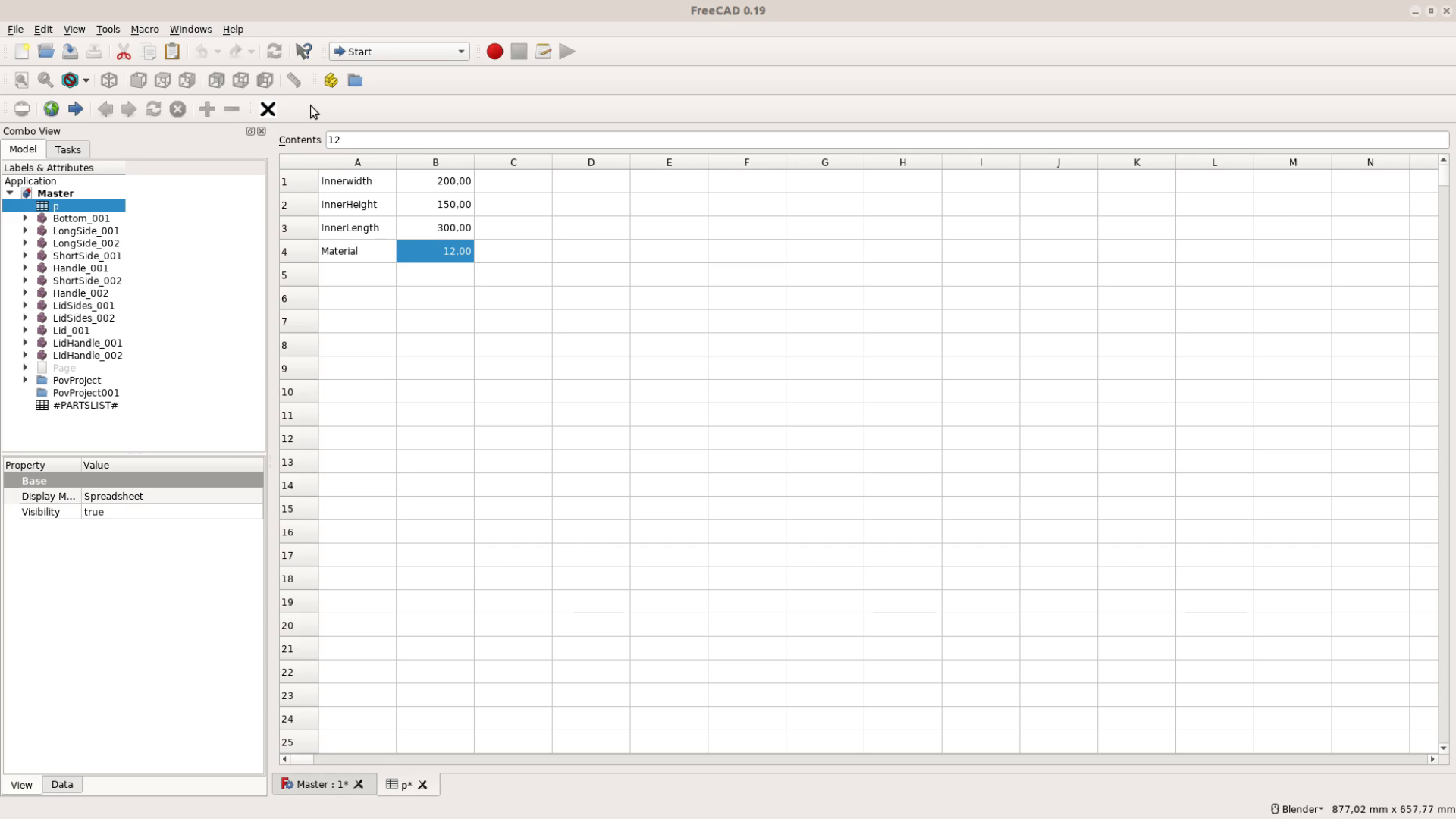
For the box these are the material thickness, as well as the inner width, height and length. We use a macro to create aliases for these numbers so that we can refer to them by name
later. We covered the creation of spreadsheets and how to install this macro on the last tutorial.
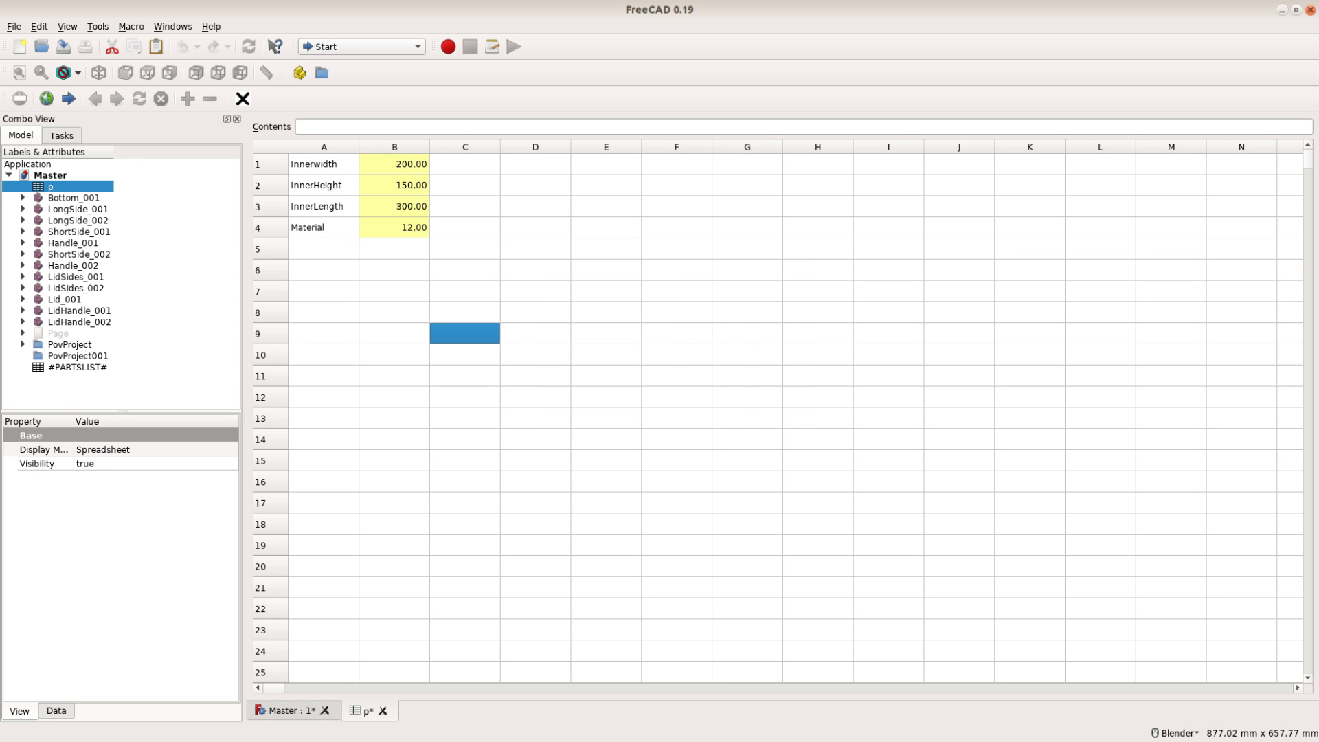
We save the file with the spreadsheet under the filename master.
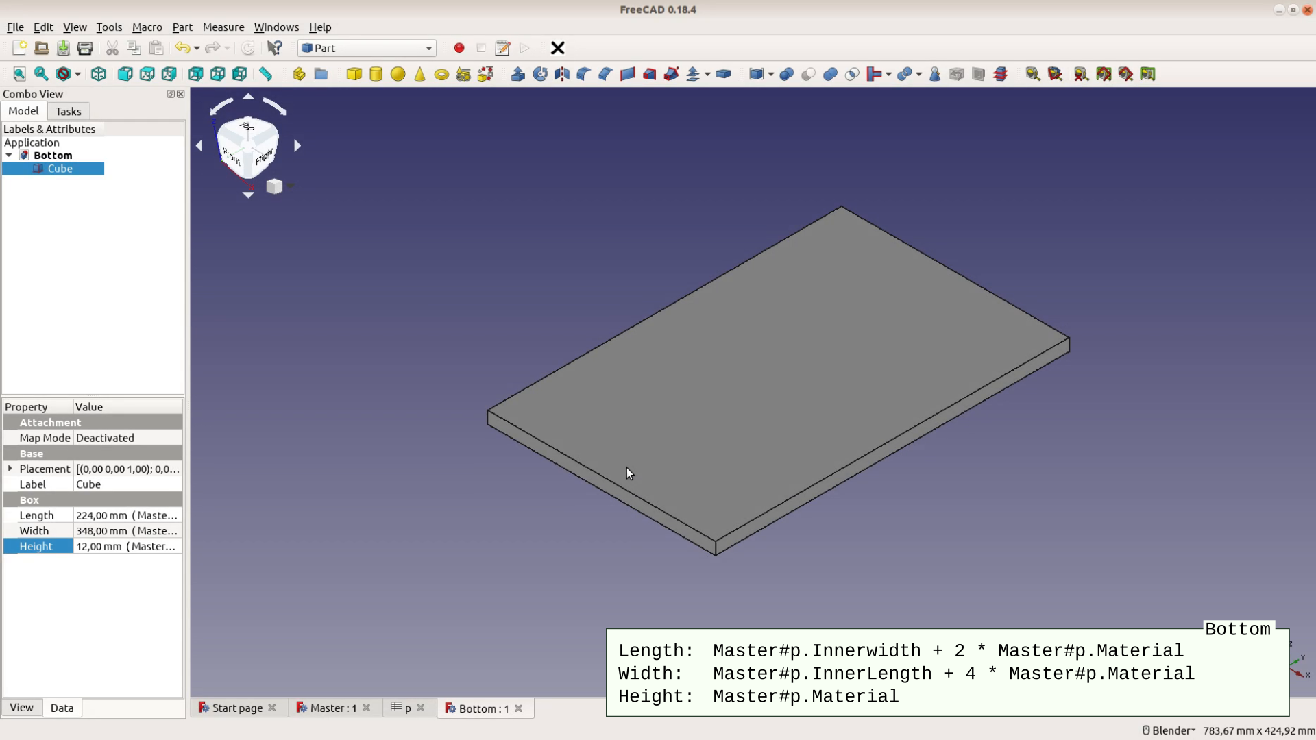
Creating the boards
Next we create a new file for each individual board. In the part workbench we add a cube. This cube gets then dimensions from the spreadsheet in the format filename, hashtag, table name, dot, variable name. This would be for example master#p.material.
The formulas are entered as we did in part 1 of this series.
We start with the bottom piece. It does not matter which dimension is the thickness so we can also use the height field of the cube for the material thickness. The length of the bottom is the inner with plus 2 times the material thickness for the side pieces. The width is the inner lenght plus four times the material thickness. Each cube gets saved as a separate file. The first one we name bottom.
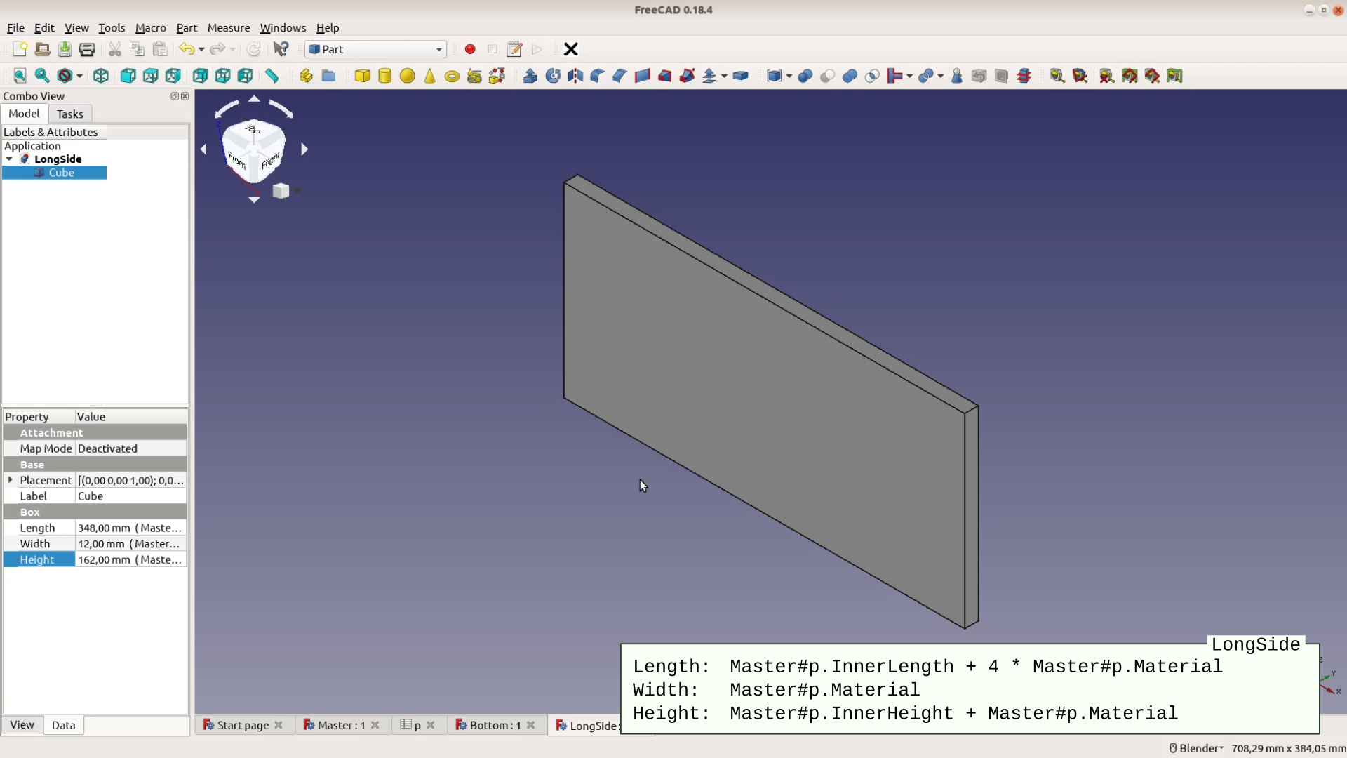
Next are the long sides. The width is the thickness of the material, the length is the same as the length of the bottom and the height is the inner height plus the material thicknes.
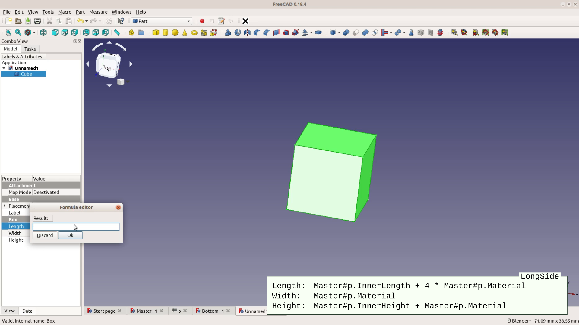
After saving this cube to a file names LongSide we get to the short sides.
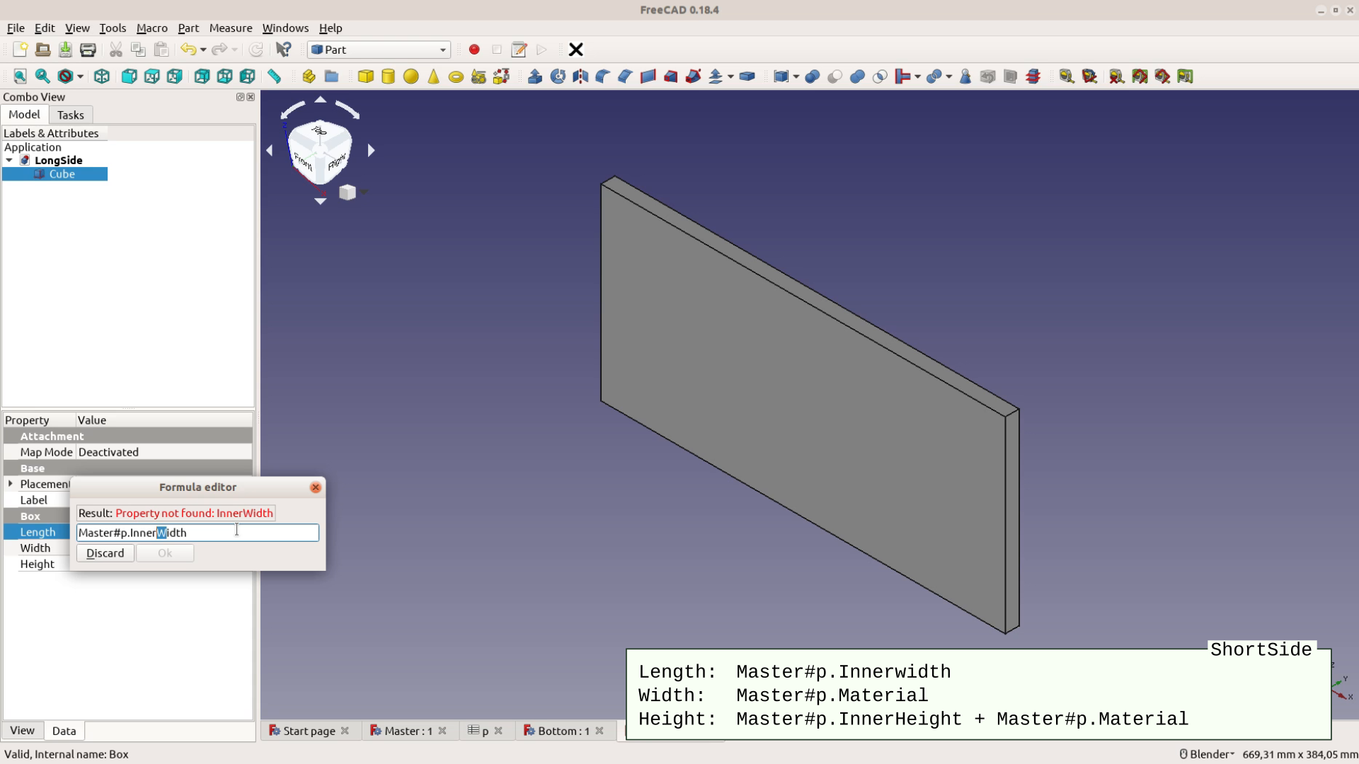
The lenght of these sides is the inner width, the width is the material thickness and the height is the same as for the long sides. We can just modify the length field of the LongSide Cube and save it with another name.
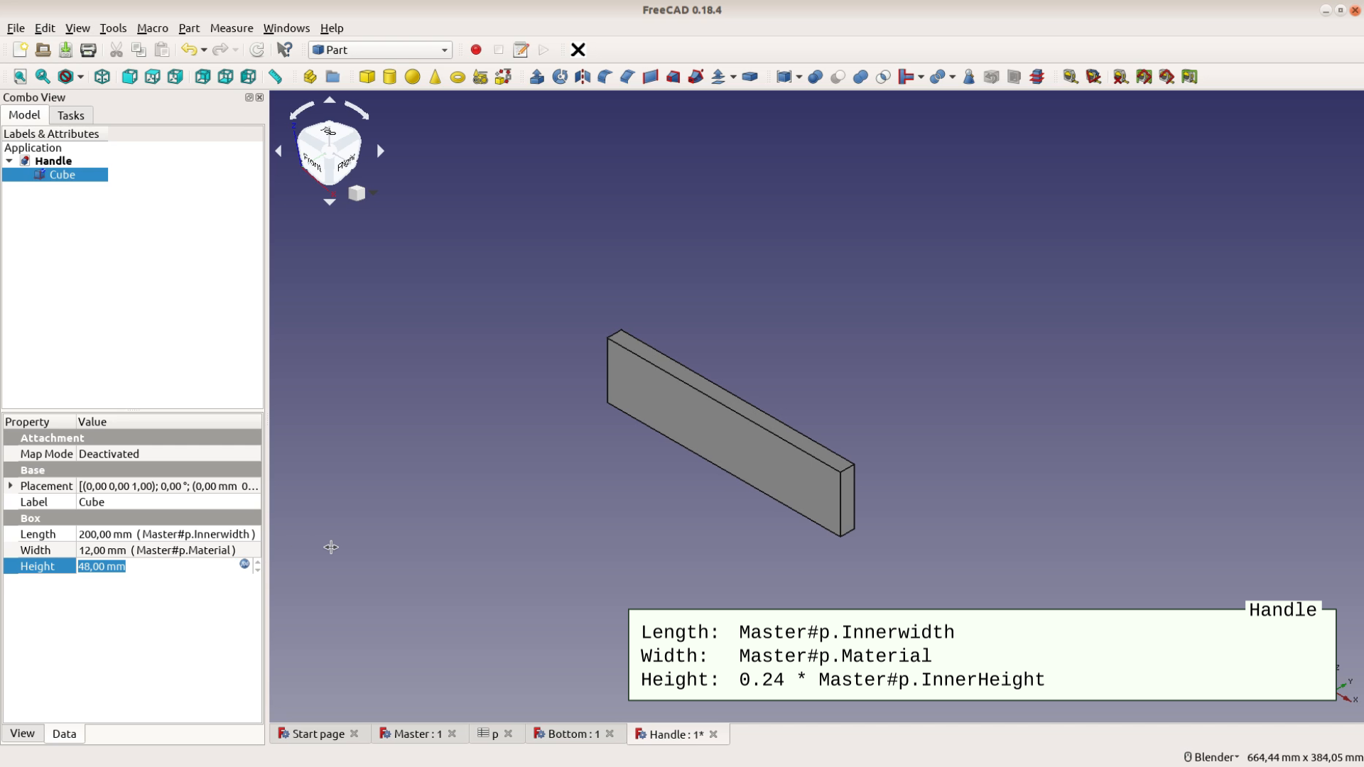
We save the File and ShortSide and then modify the height field to be a fourth of the inner height. This cube is saved as our handle.
For the top pieces that will hold the lid in place we add two times the material thickness to the length field of the handle and make the height 4 times the material thickness.
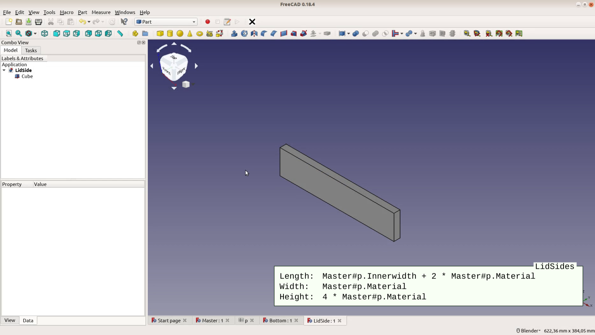
After saving this cube as LidSides the components of the box are done and we only need two more cubes for the lid. The lid handle is easy as it is nearly identical to the lid sides. We just modify the height field to be 2 times the material thickness.
The last piece is the lid itself. The width is the inner width, the height corresponds to the material thickness and the length is the inner length minus 2.1 times the material thickness.

FreeCAD Assembly 2+ workbench
After creating all the files following the same schema we make sure the Assembly 2 plus workbench is installed. Go to Tools, Addon manager and install the latest version.

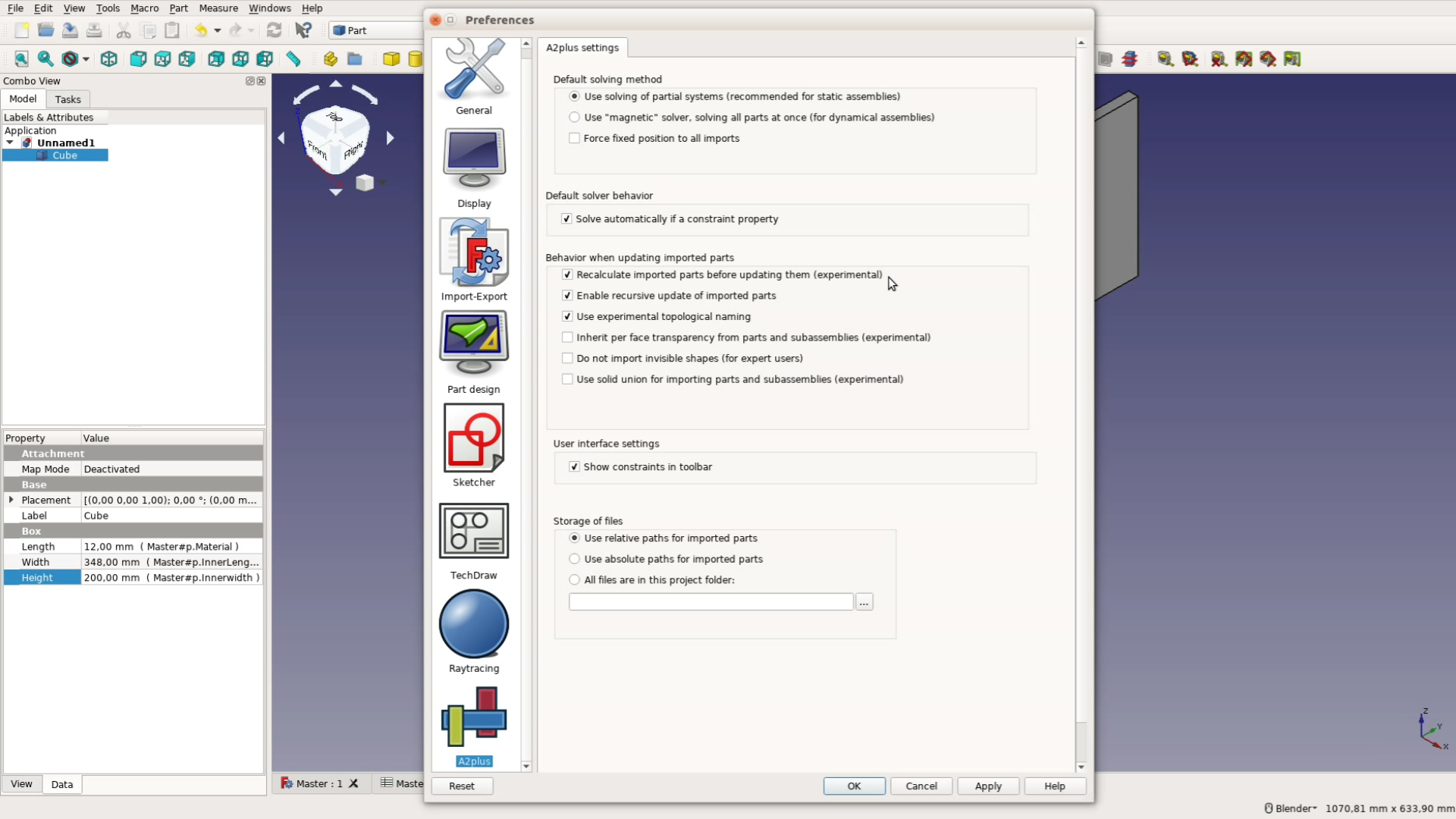
Also make sure that in Edit, Preferences, A2plus the checkboxes for “Recalculate imported parts before updating them” and “Use experimental topological naming” are enabled.
Finally the assembly in FreeCAD
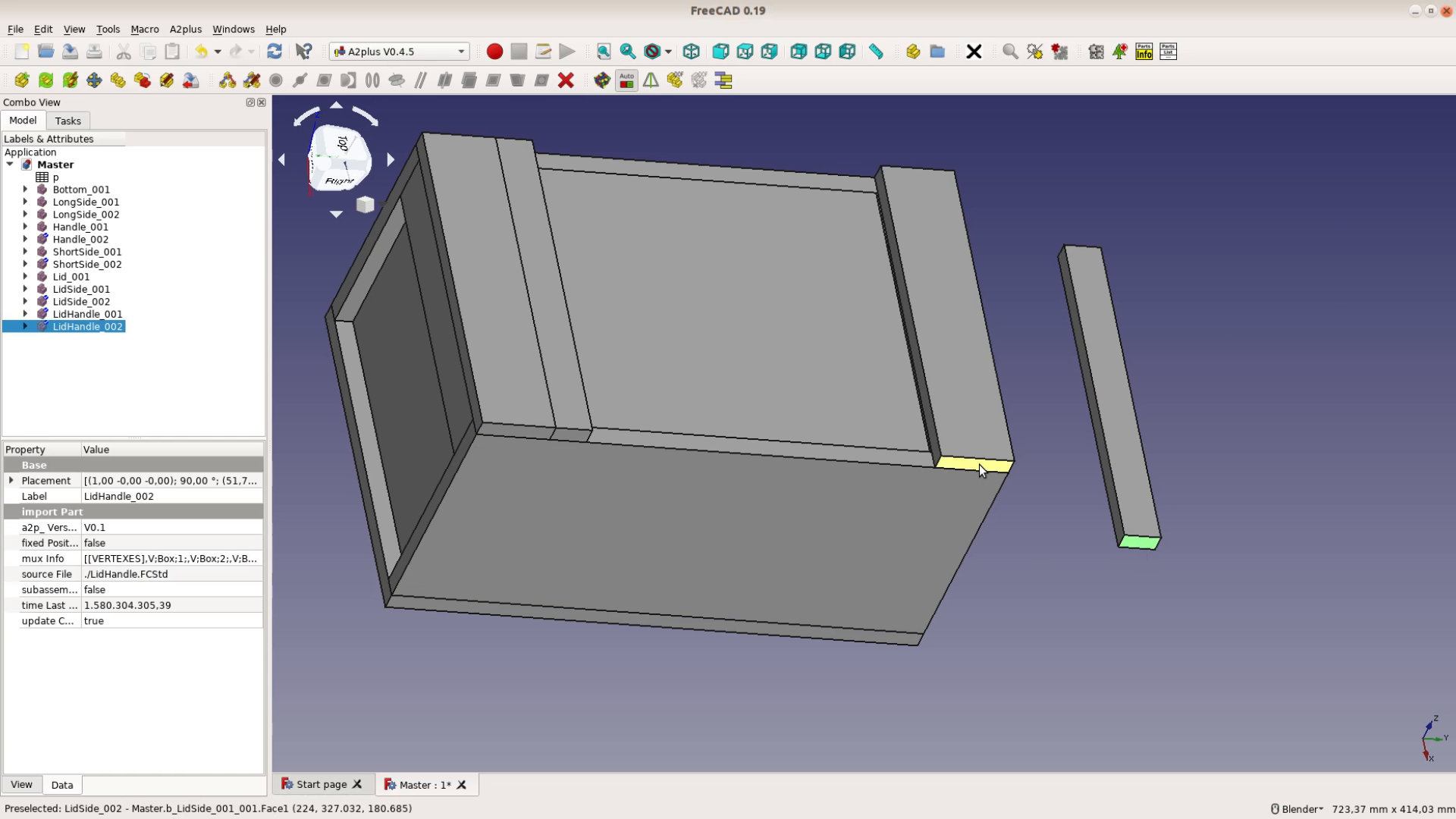
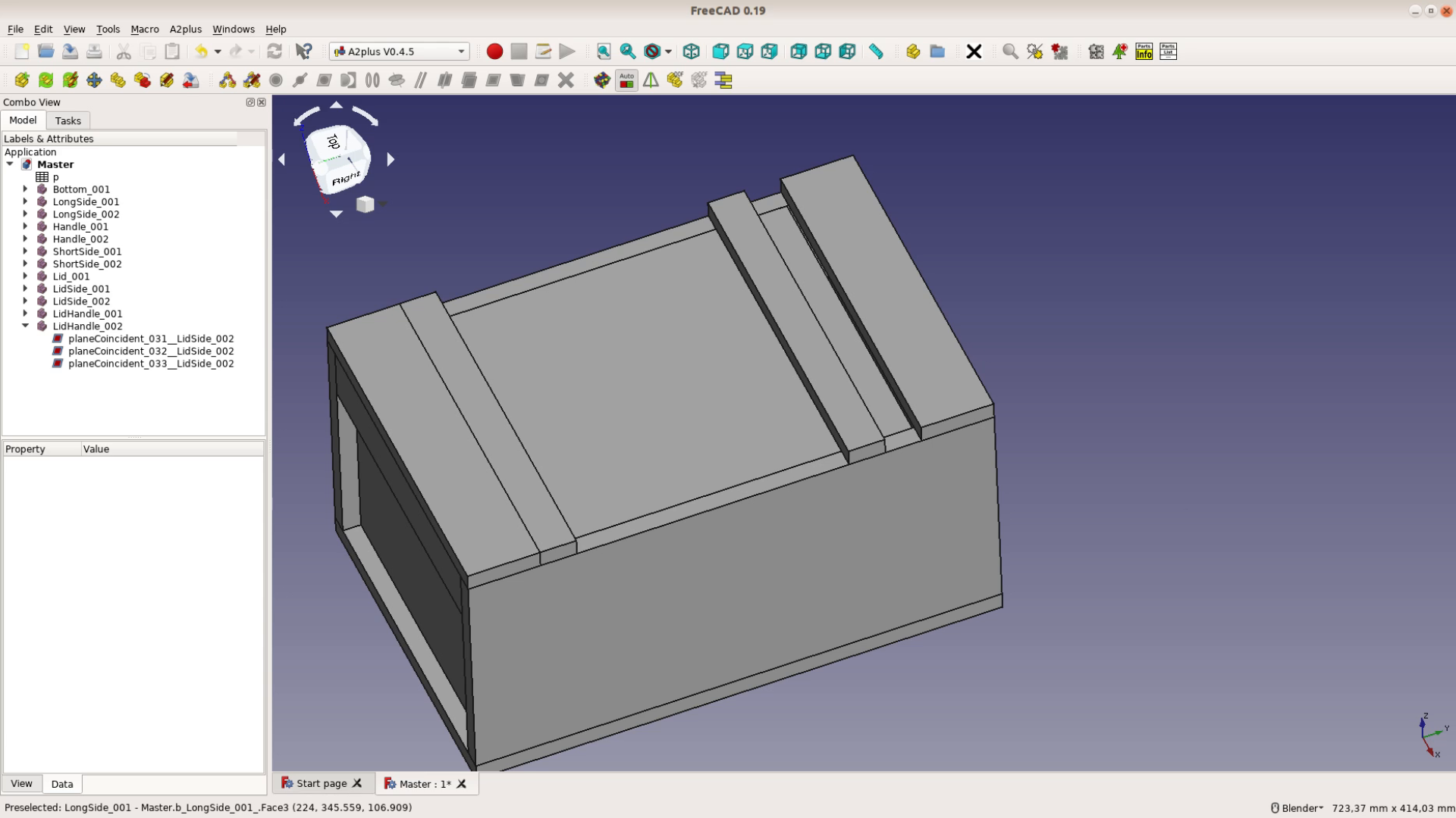
After switching to the A2plus workbench we can now import the individual parts one by one with the button that shows a plus sign. These parts can be aligned with one another in a variety of ways. For woodworking projects most of the assemblies can be solved by making planes coincident.
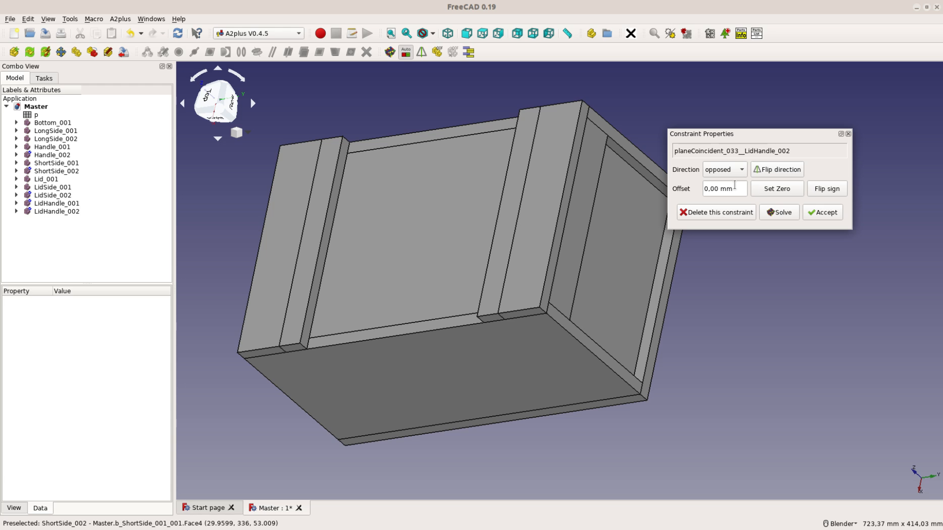
Just select two faces that you want to align while holding down the Ctrl key, click on the plane coincidence button and decide if the two objects are opposed or aligned with one another. After aligning three faces a board is locked in place.
If we need a copy of one of the parts we can duplicate it with the button that looks like a staircase.
Assembling a project this way is fast and actually quite fun.

It is worth noting that there are several other assembly workbenches in FreeCAD. In particular the new Assembly 4 workbench is worth to take a look at. We will stick to the Assembly 2+ workbench for this tutorial series as we will look into using it to create cultists in the next part of the series.
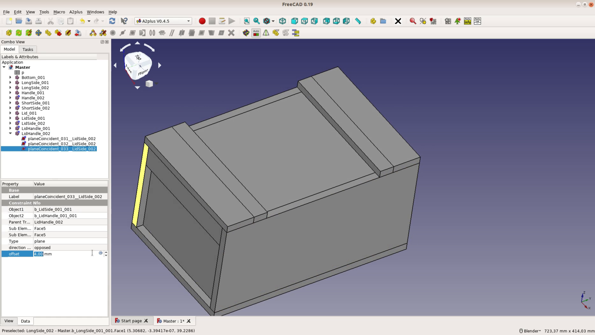
When putting the last lid handle in place we dont’t want it to sit directly against the side piece. Just add an offset to the plane constraint and we are good to go.
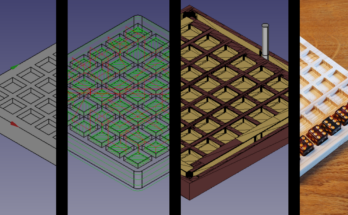
The great thing about this model is that it is fully parametric. We can for example decrease all the values to scale the box down to a size of a few centimeters.
After cutting the small shapes on the lasercutter we can assemble a miniature box for small parts.
Je possède Freecad 0 18 3. Je n’arrive pas à télécharger l’atelier d’assemblage A2+ par Adon manager. Rien n’apparaît dans ce dernier quand je l’utilise . Alors que dois-je faire ?. Je suis en version Windows 7 (32 bits) . Merci de bien vouloir m’aider.
I would suggest that you use FreeCAD 0.19.
It seems that a change in Github caused this problem. You can download the a2plus and unzip into the mods folder. See https://github.com/kbwbe/A2plus and follow the “Manual Installation” section.
Or, as WayOfWood suggest, maybe FreeCAD 0.19. would work.
I have an A2plus assembly that I created and one of the parts is CNC cut. In FreeCAD I used the PART (not part design) workbench and boolean operations to define the CNC cut part. When I go back and edit an early part of the design (a simple hole diameter made prior to the boolean operation) I can successfully make the edit but I can not make the change progress forward into my final A2plus part.
I have tried various combinations of refresh, mark for recompute, recompute and anything else I can think of. After an assembly is made what it the missing step that allows part modifications to move forward and appear in the final assembly?
I am using Linux and the 0.19 version of FreeCAD from reeCAD_0.19-23964-Linux-Conda_glibc2.12-x86_64.AppImage.
That is weird. If you did an update of the chart and it does not work I would suggest you open a ticket on the bugtracker of A2p.
Great instructions, but I have a problem I can’t figure out. I made the box as shown in the video using a spreadsheet for the values. My problem is if I change the values in the spreadsheet, when I redraw the model some of the pieces do not stay attached. I noticed that a few parts still have some DOF, but I don’t know how to fix that. I’m still learning FreeCAD and this is my first try with A2plus WB.
hello, thanks a lot for this tutorial, i did it all for my first project with freecad and it worked flawlessly.
I would like to ask for some orientation if I wanted to add another variable to the partlist, say for instance the total perimeter of the boards im using??
I know some python but im rusty and i can not figure it out yet.
Thanks a lot again
You can look into the file where I calculate the volume and take this as a template