In this article we 3d print a jig that converts a simple ruler into a DIY marking gauge. It’s a cheap alternative to an expensive combination square.
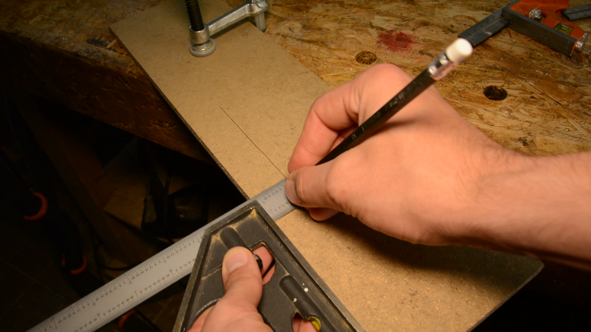
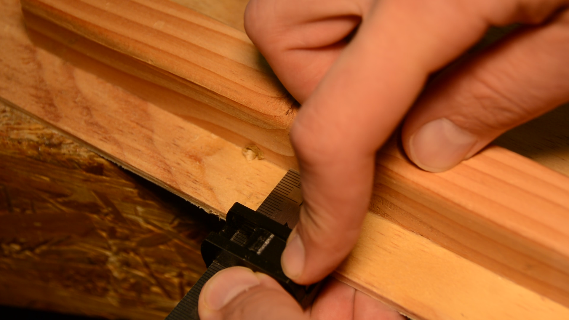
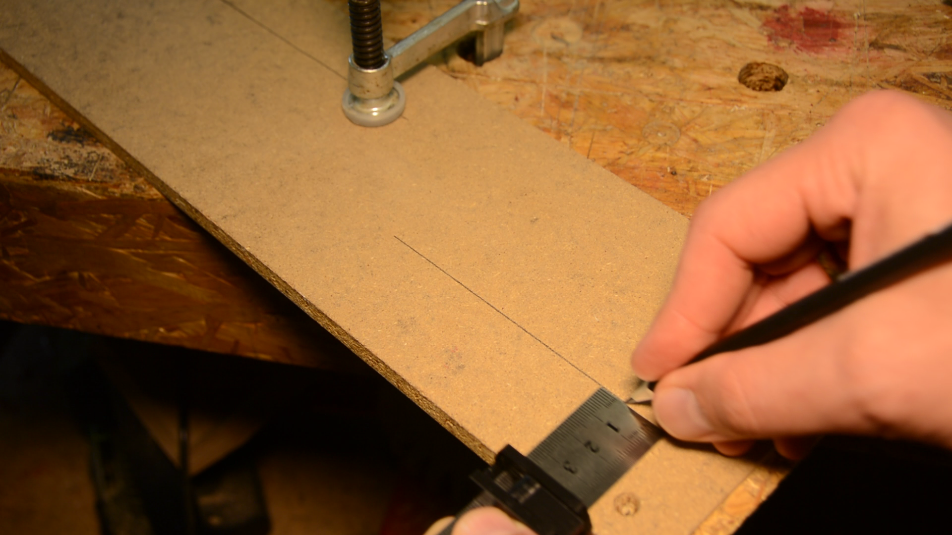
The combination square is one of the most used items in my shop. I mainly use it to measure and to mark a distance from the edge.
Over time we accumulated quite a few of these combination squares in the shop. However I am using them as a kind of story stick. That means I have one of them set to the distance of a mark from the edge, the other to the depth and so on.


When you try to keep the important measures of a project all locked in place you are quickly running out of combination squares. While combination square are quite expensive these stainless steel rulers retail at 4 Euro for a pack of three – shipping included. Wouldn’t it be great to have a making gauge or combination square replacement for less than 2 bucks? The final result has a small lever to securely lock the position with one hand.
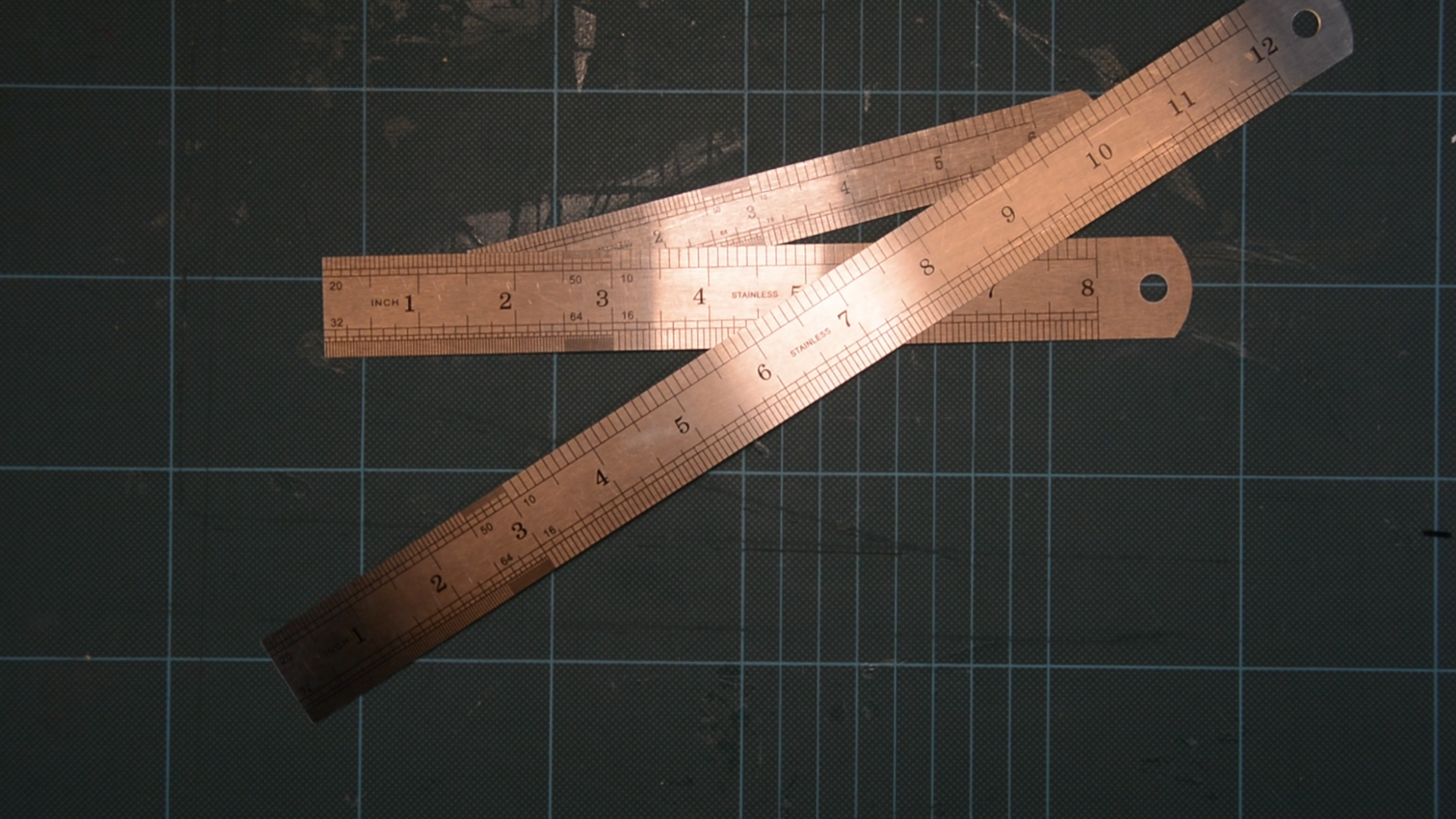
You can use it for measuring as well as for marking.
3d printing the DIY marking gauge
Creating such a tool is super easy – at least in theory.
You just need a steel ruler, a nail and a 3d printer.

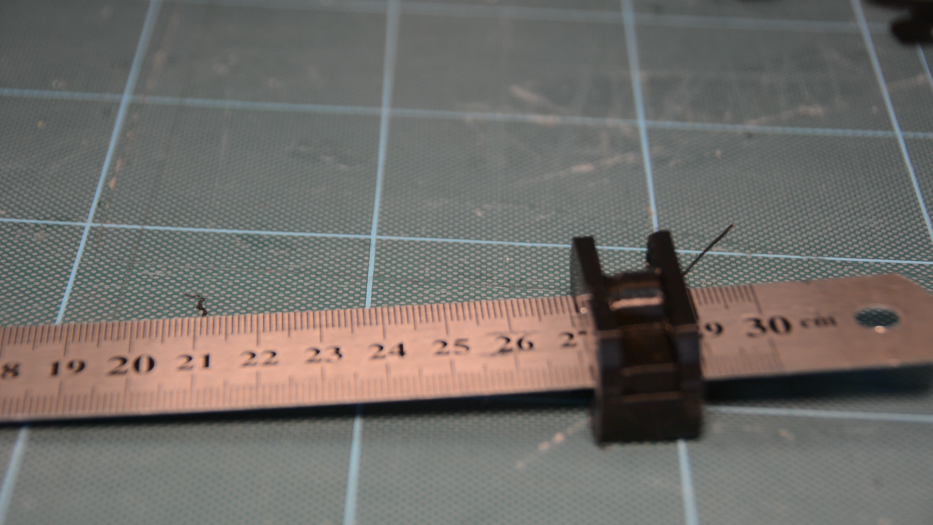
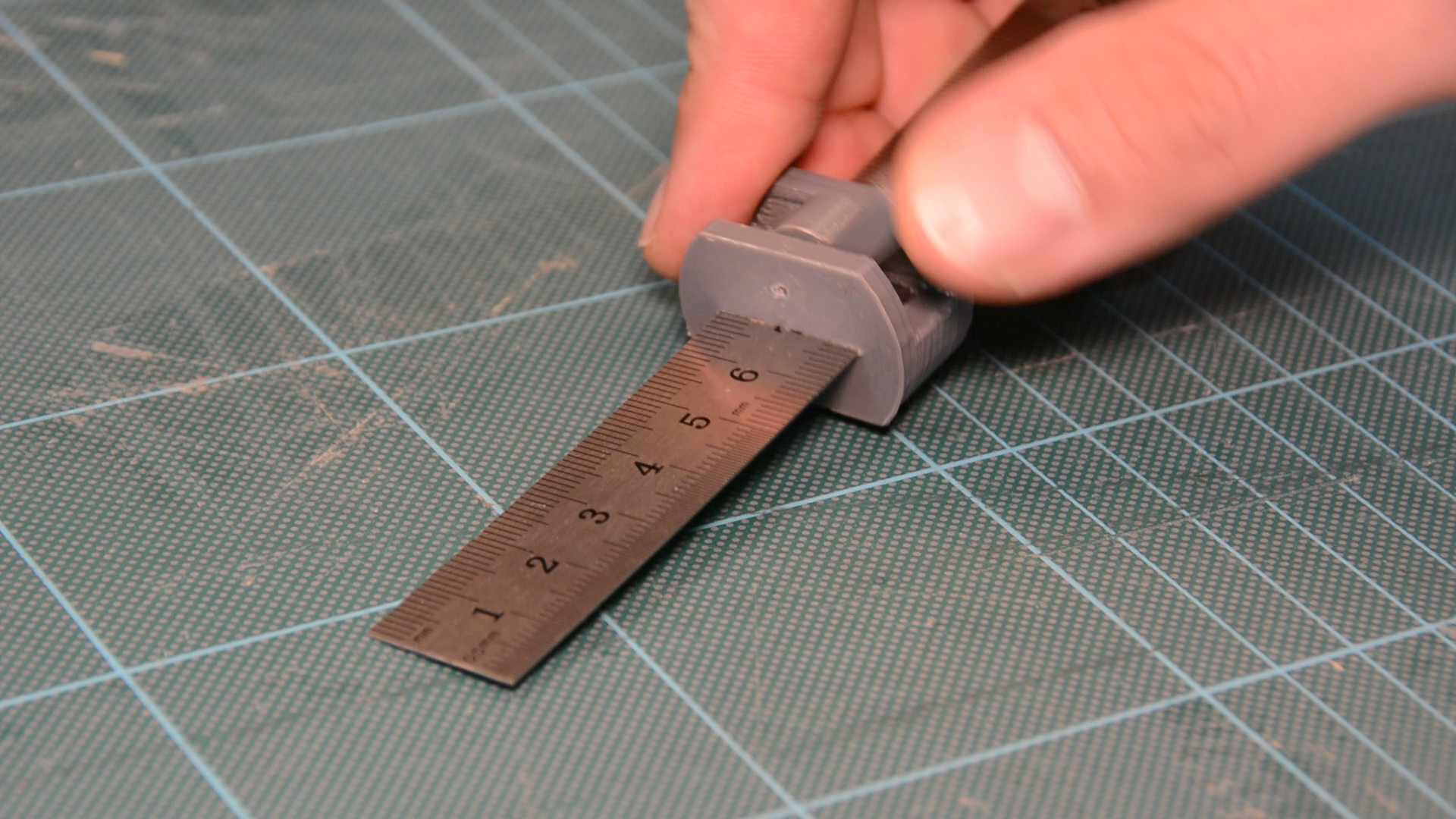
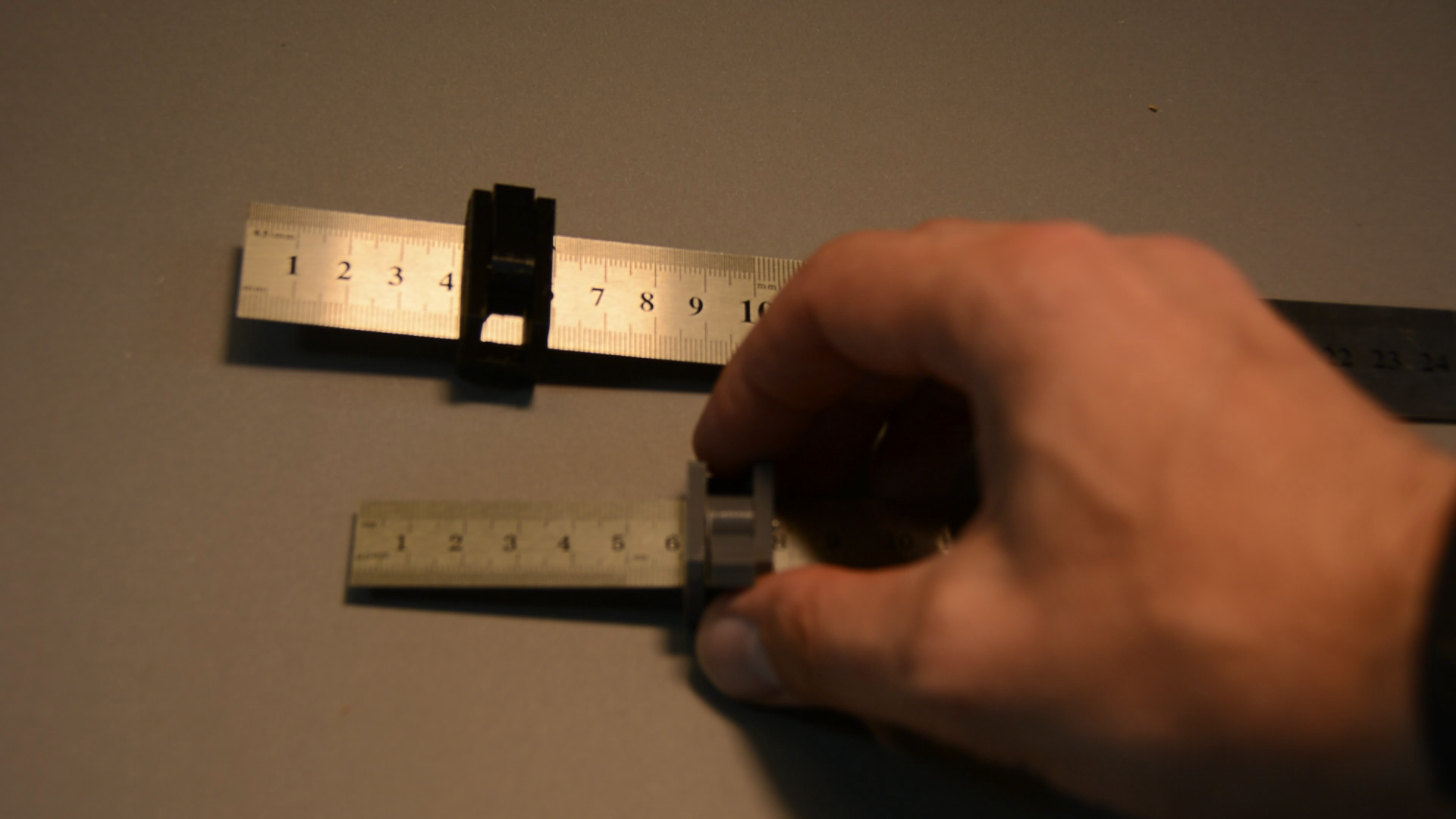
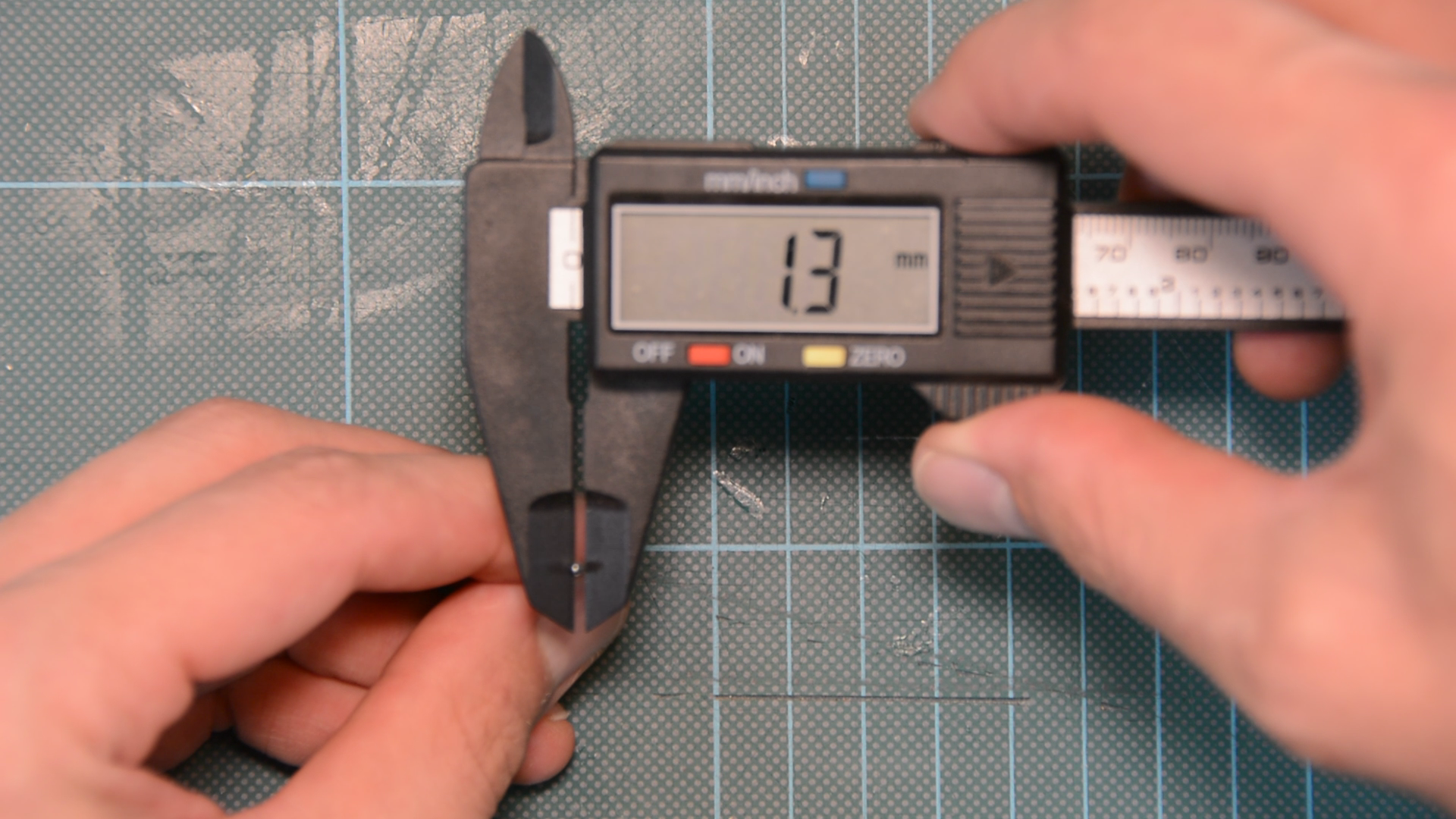
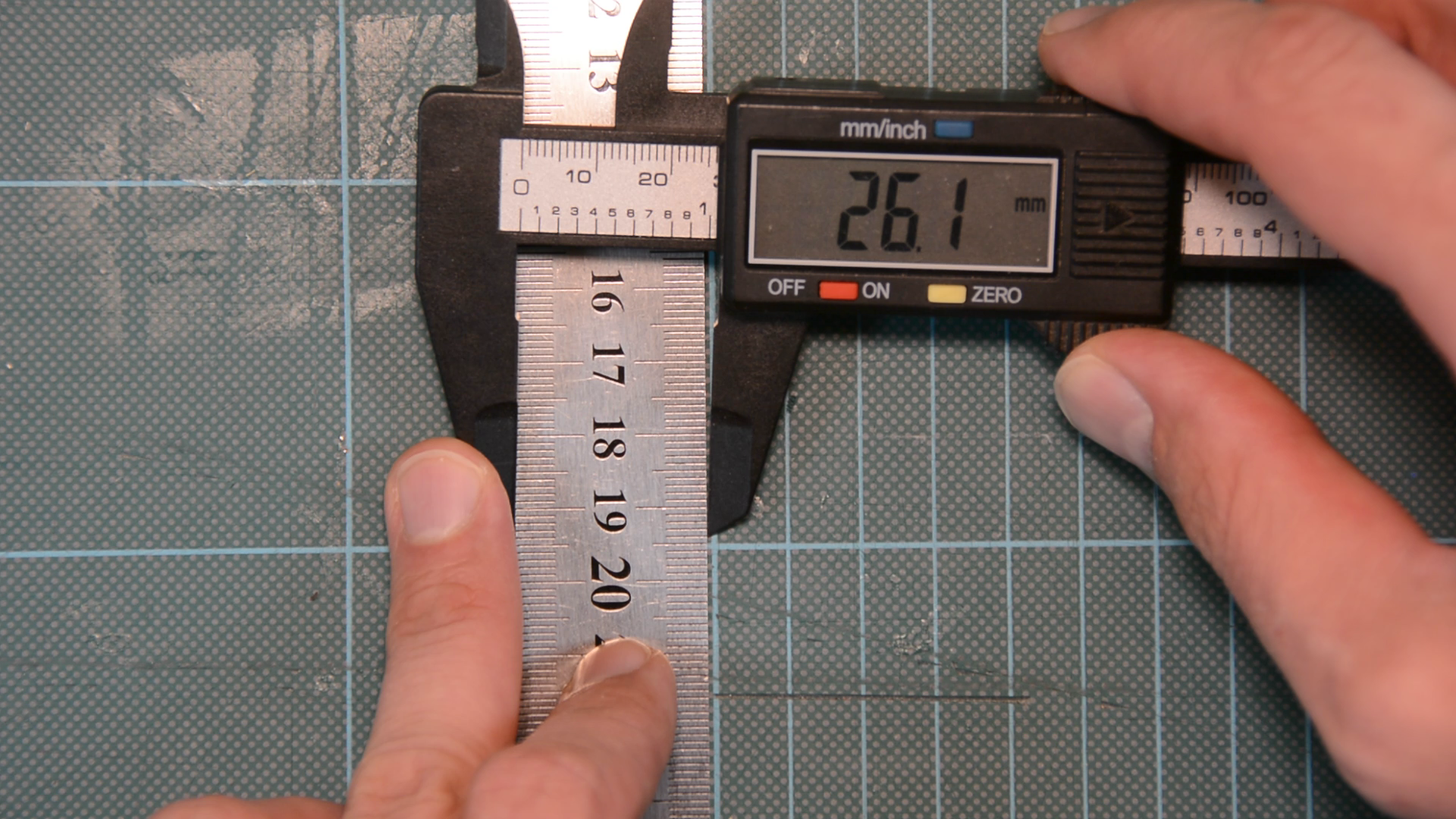
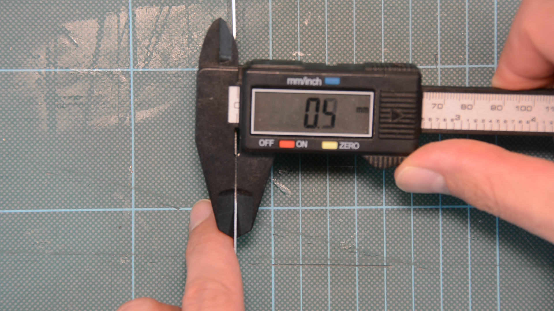
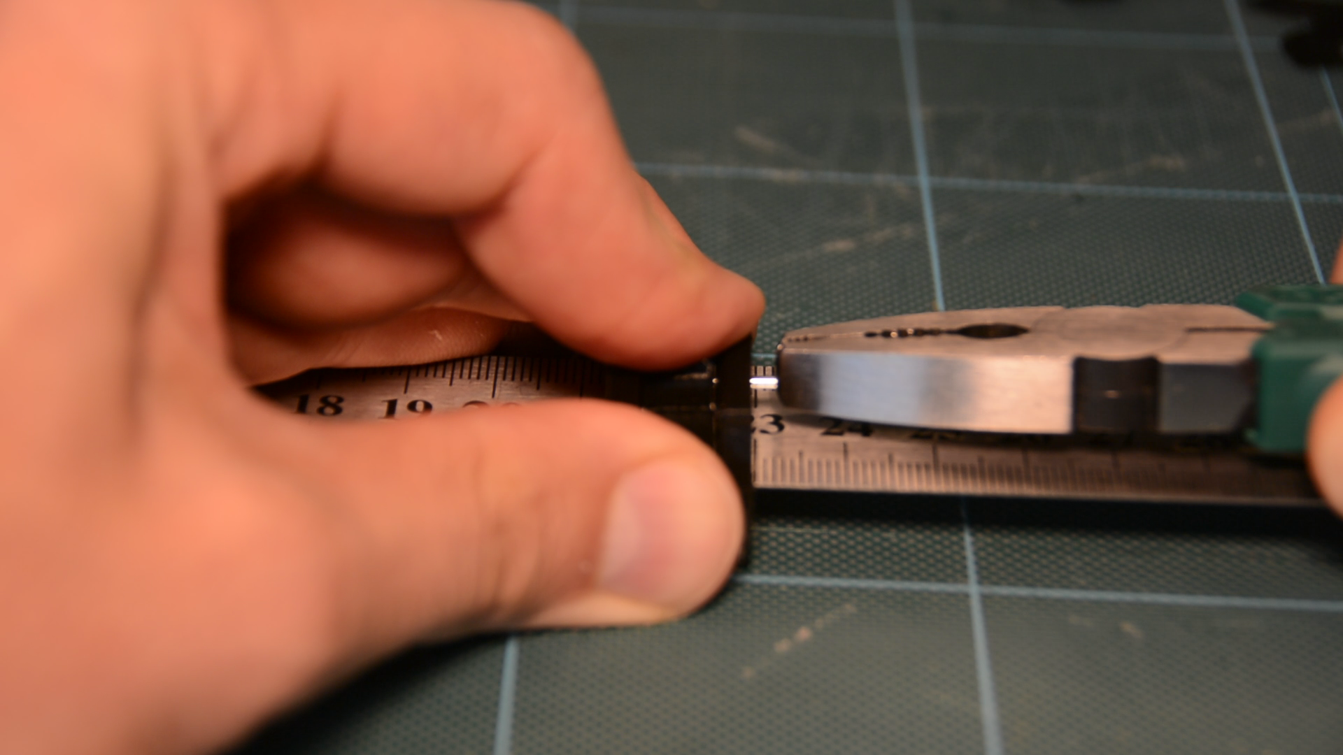
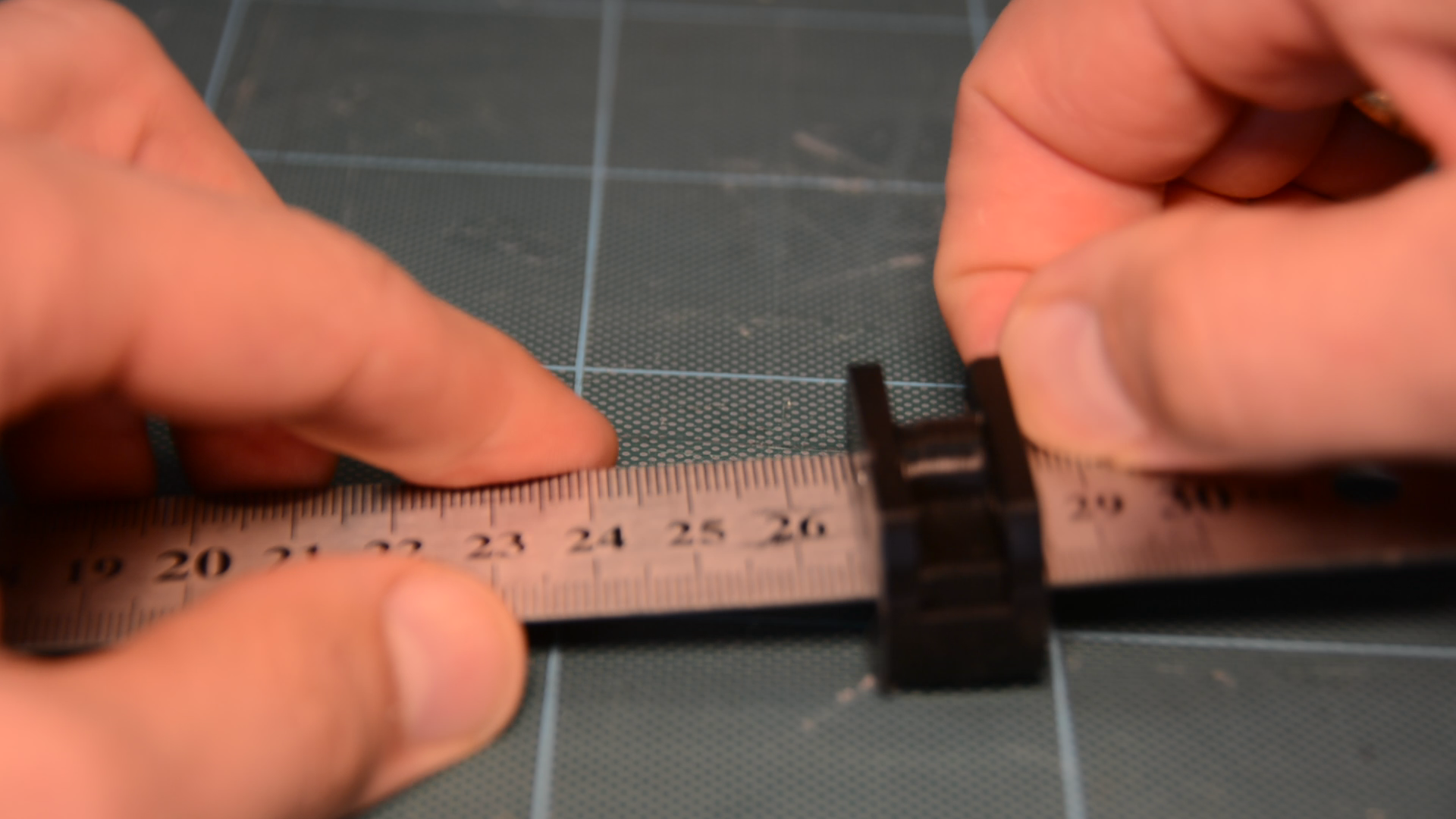
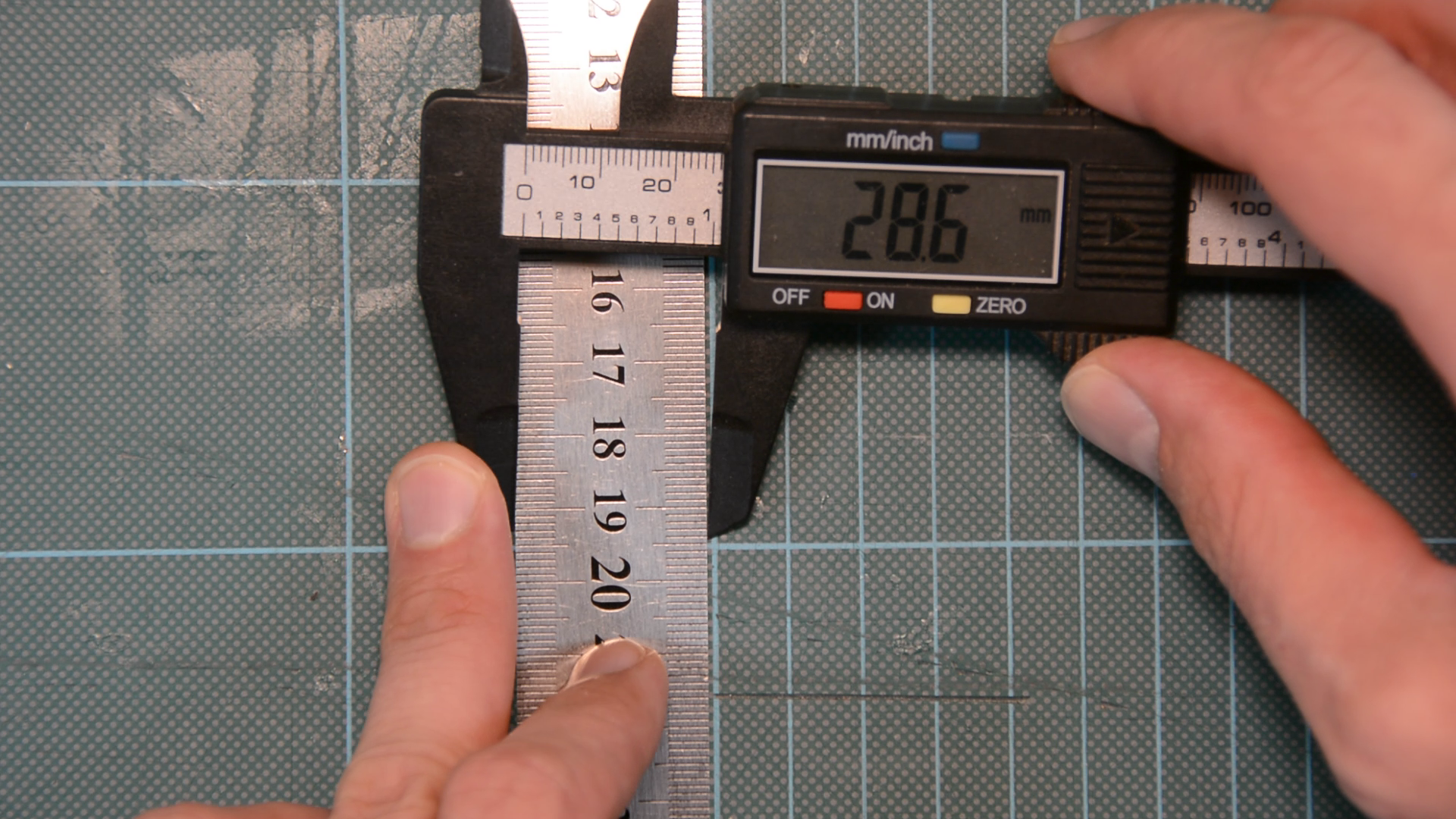
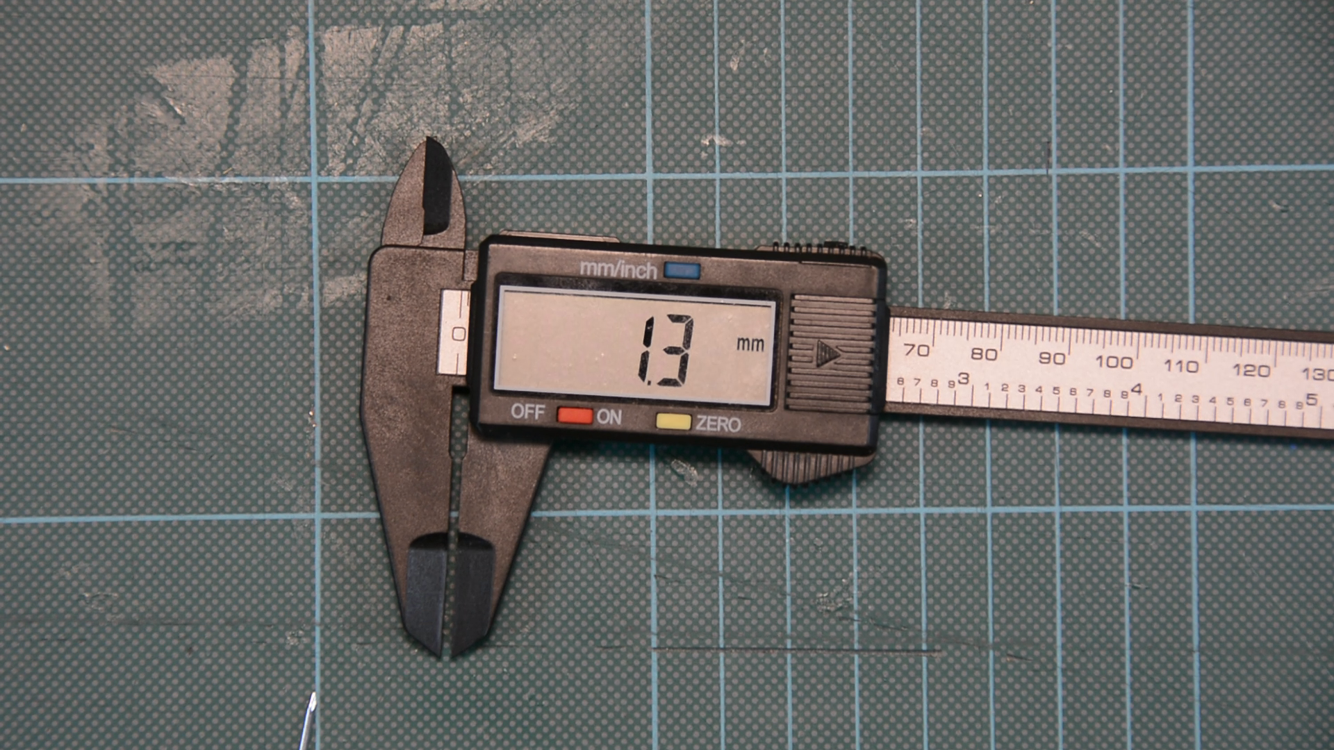
First you have to measure the diameter of the nail, the width of the ruler and the thickness of the ruler – all these dimensions should be measured quite precisely.
Then go to my Thingiverse website, type the numbers in the customizer and download a customized STL file for free.

Send it to the printer and in an hour or so you have everything you need.
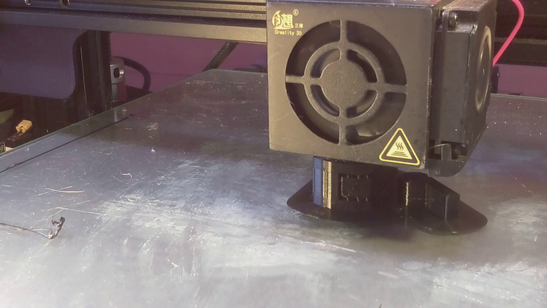
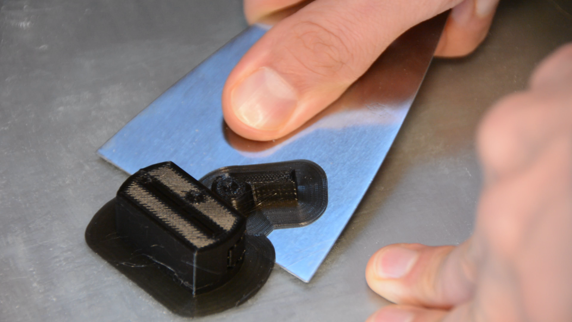
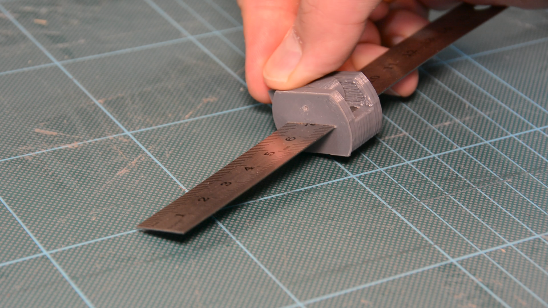
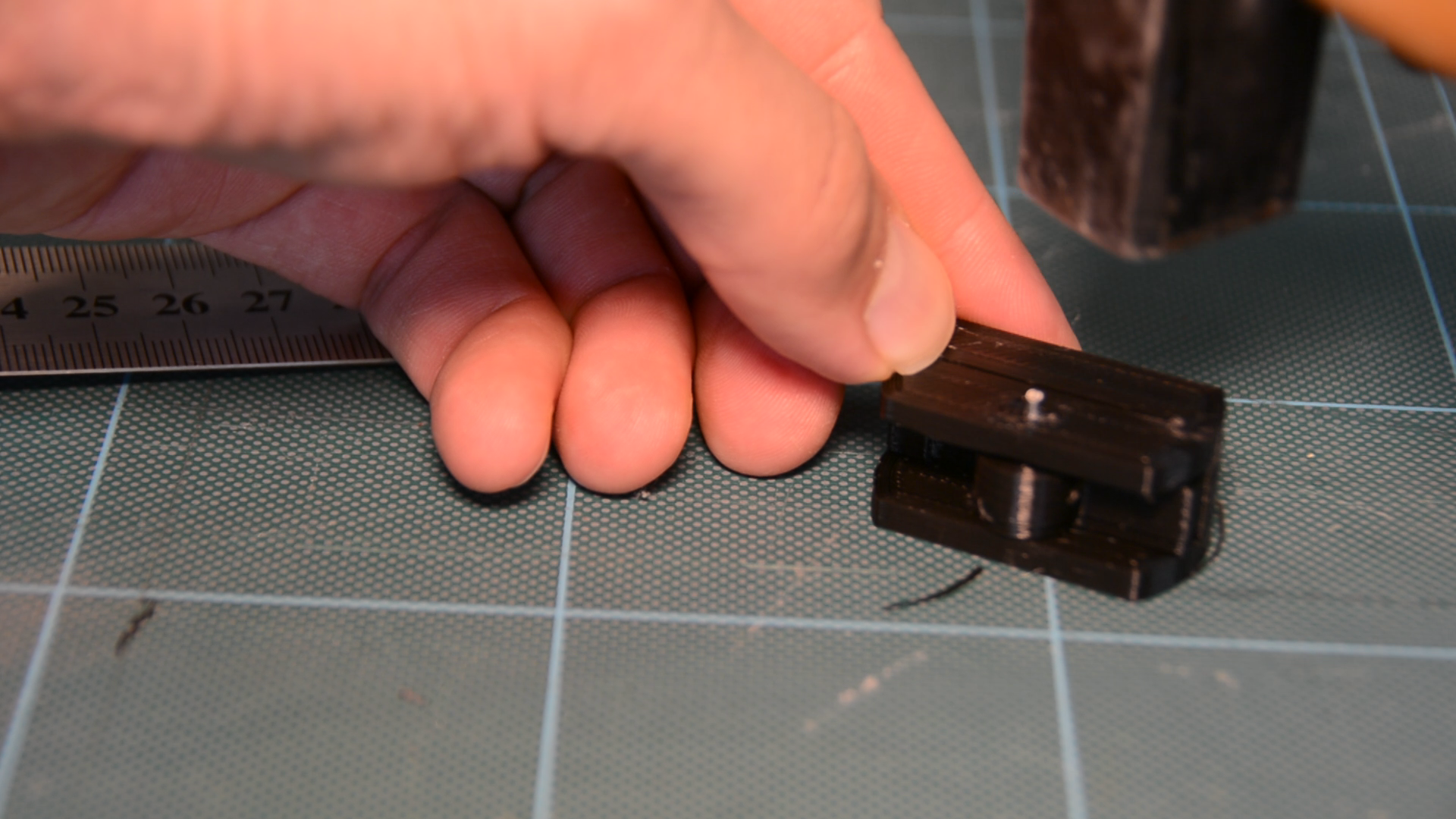
Insert the steel ruler in the slot and make sure it slides freely.
Use a thin needle to align the holes in the sides with the hole in the lever.
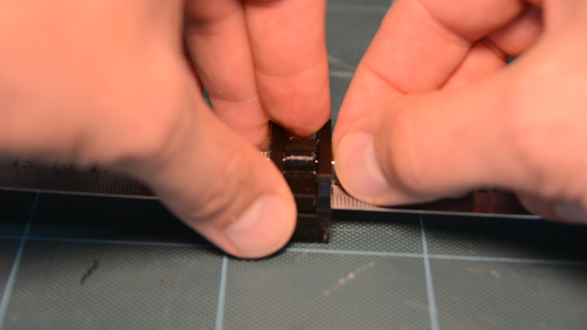
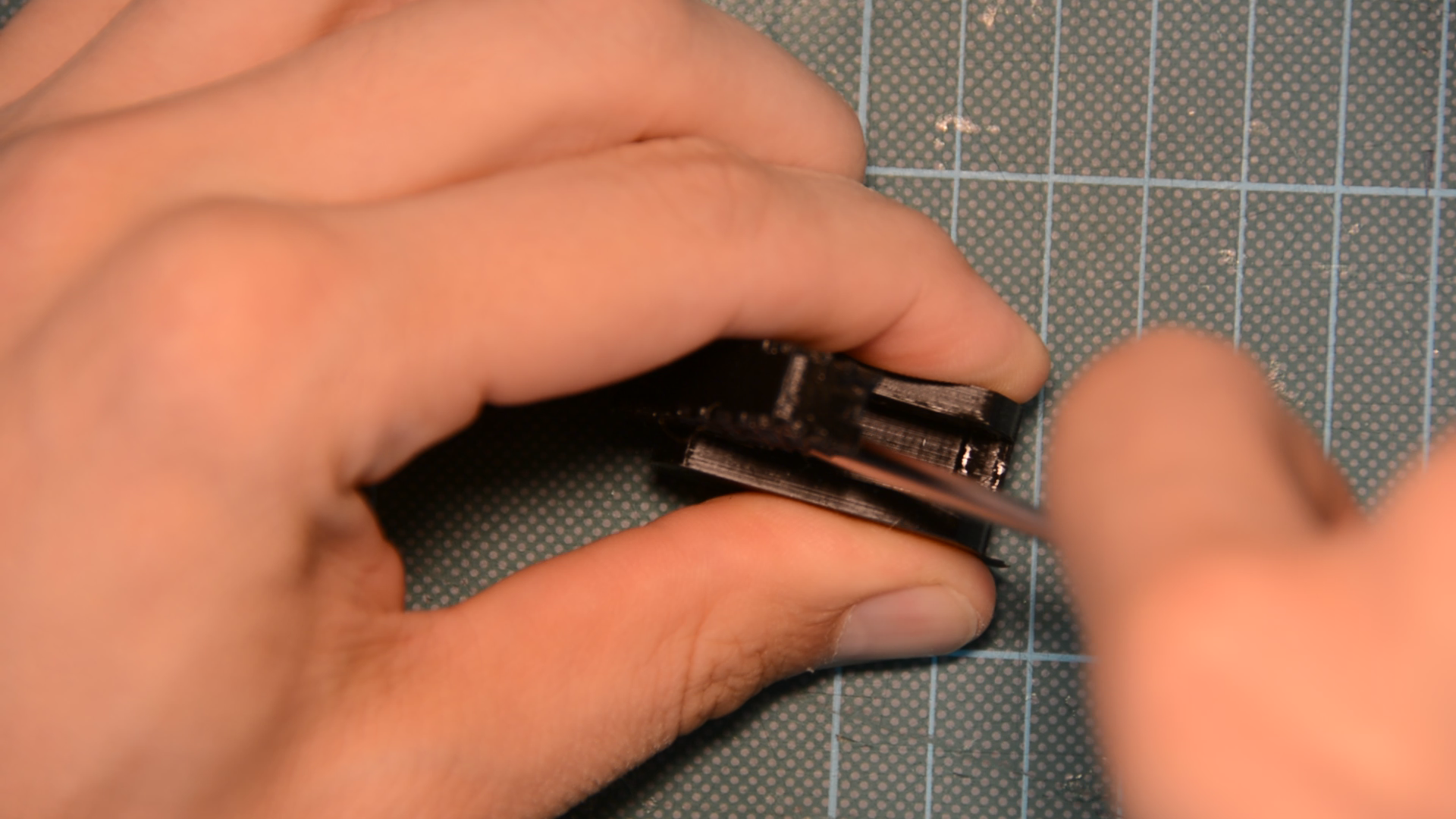
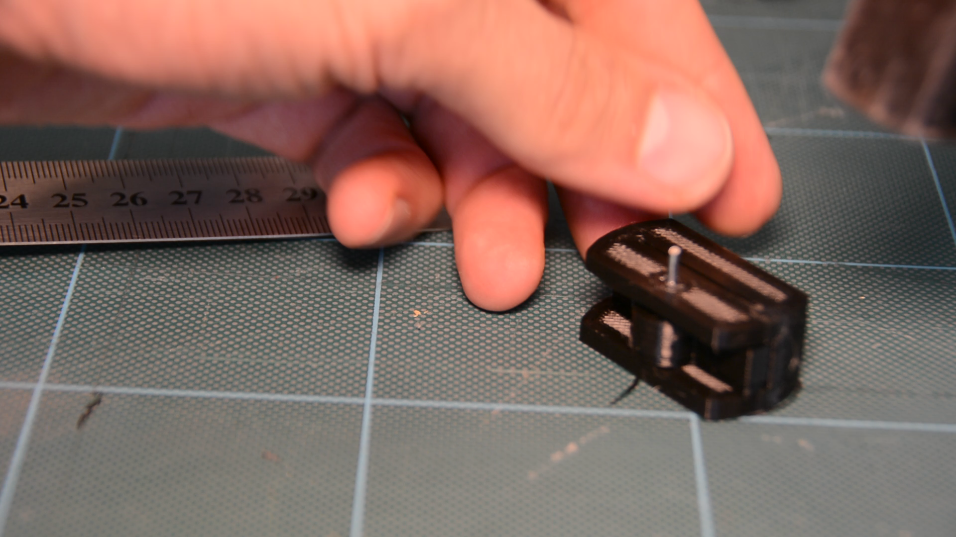
Then clip a nail to the width of the marking gauge and press fit it into the hole.
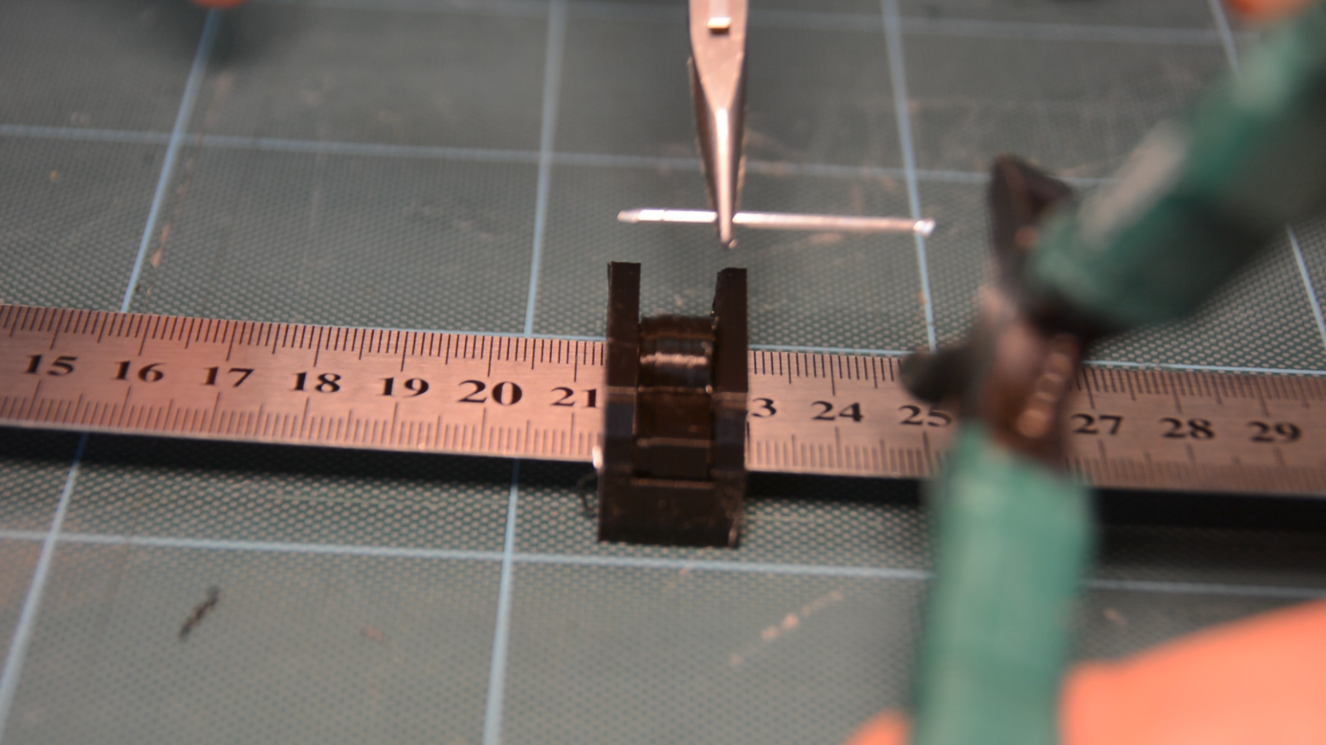

After it touches the lever you can drive it down with a hammer and the marking gauge is ready.
Mistakes to avoid
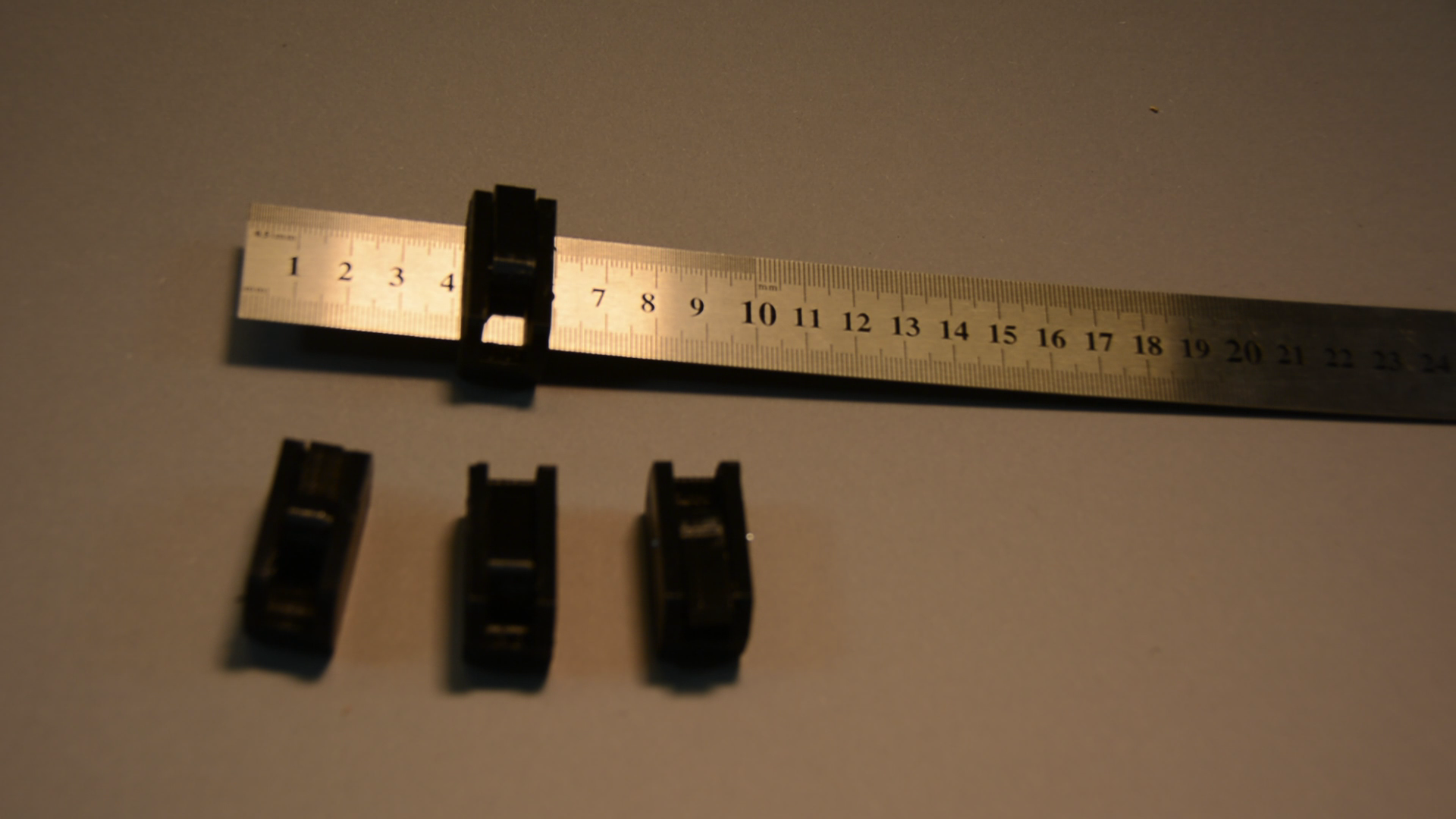
That’s the theory but in practice it took me 9 tries in order to get the DIY marking gauge prototype right. Let me share my mistakes so you don’t have to repeat them.
Let’s take a quick look at the design to understand why it is so tricky to get it right.

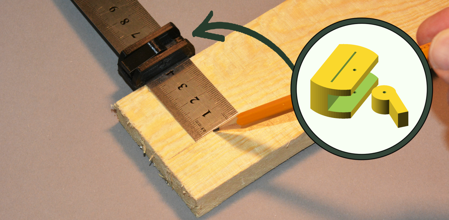
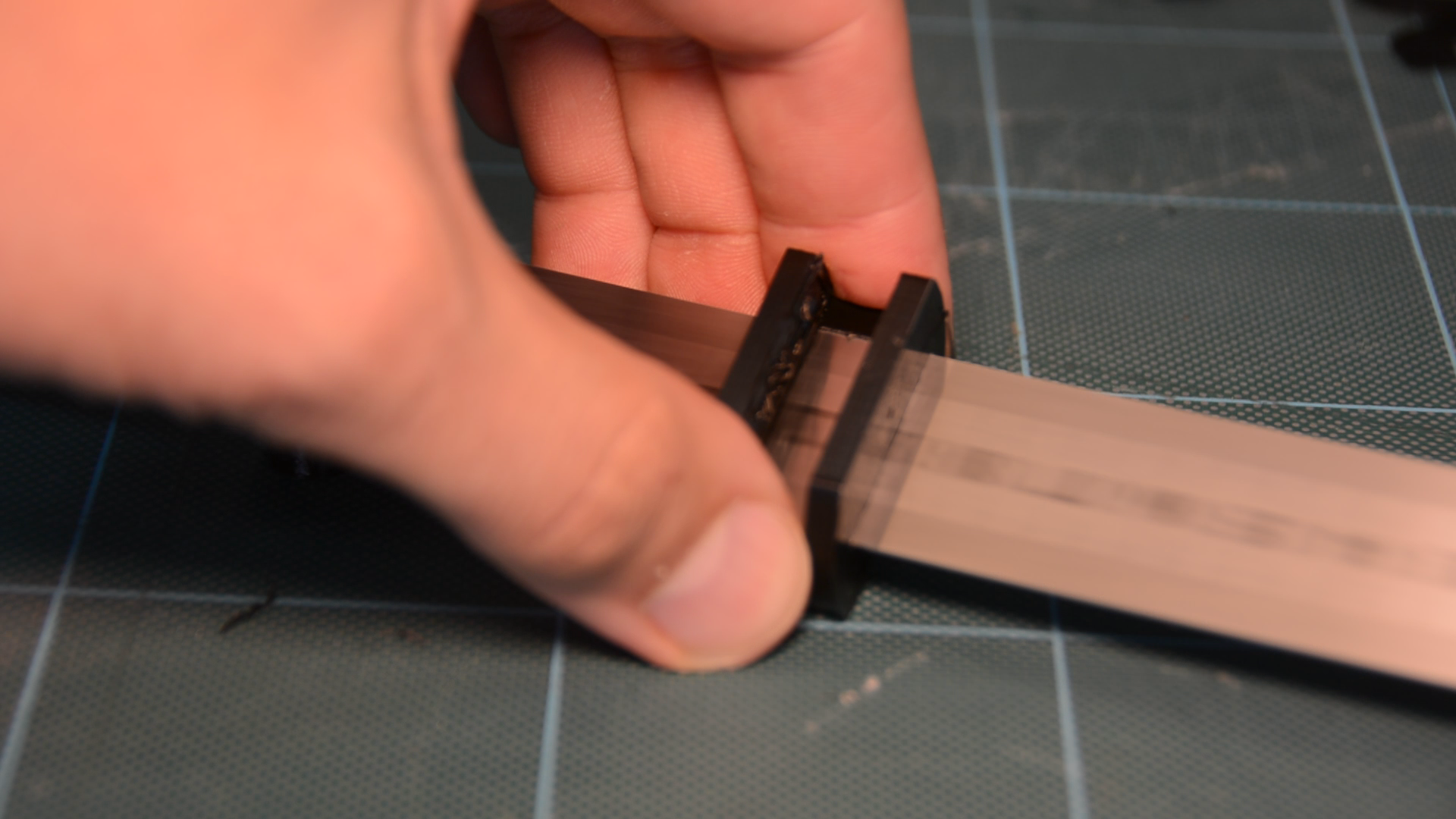
I wanted to have an eccentric lever rather than a screw so that it would be easy to lock the position with one hand. In the side view you can see very well how moving the lever is holding the ruler in place by friction.
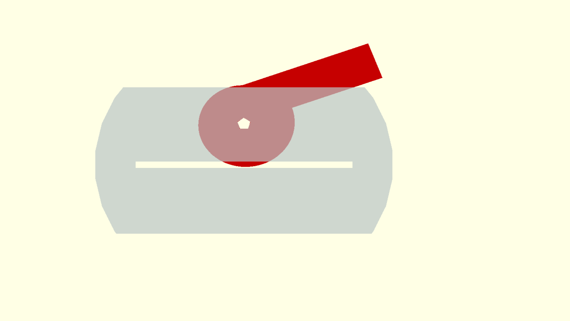
But this picture also gives you an indication how little margin of error we have in this construction.
Getting the width and thickness right
The first parameter is the with of the ruler. This parameter is critical.
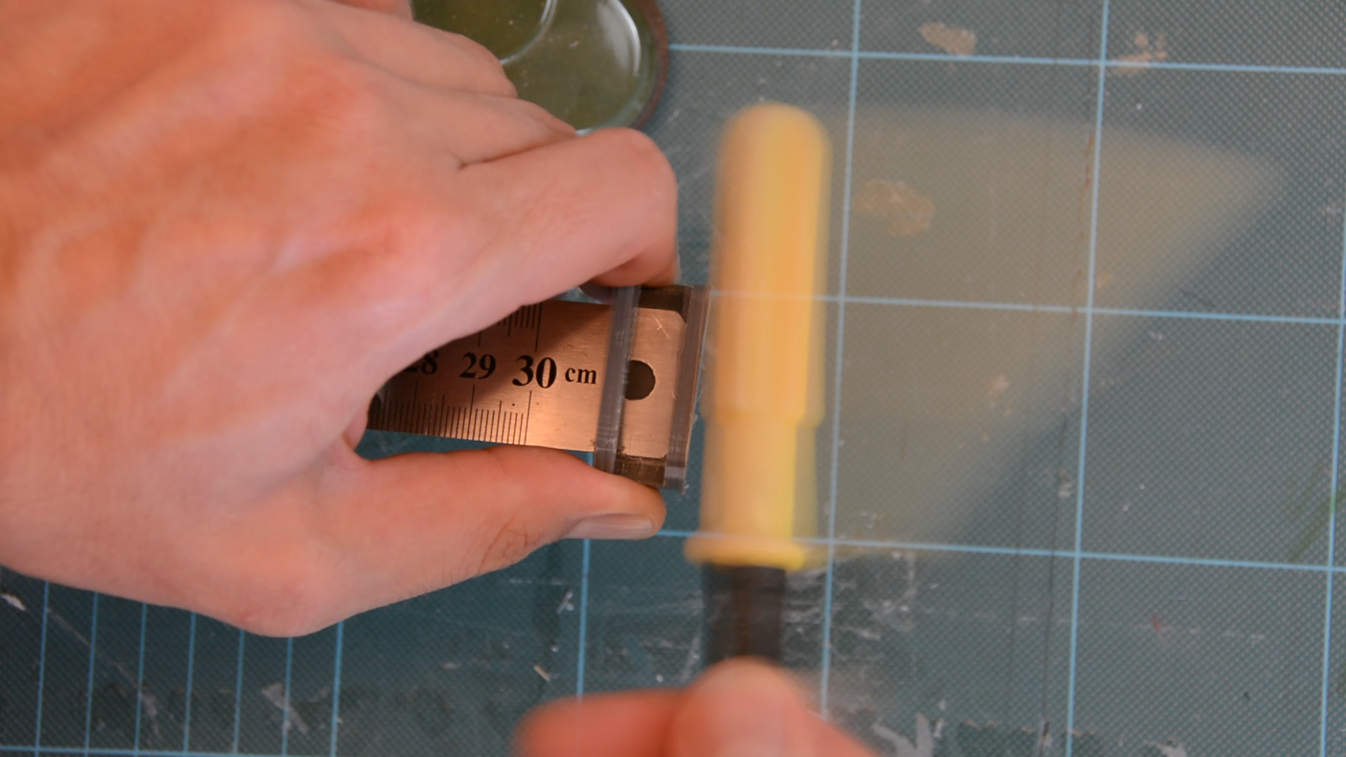
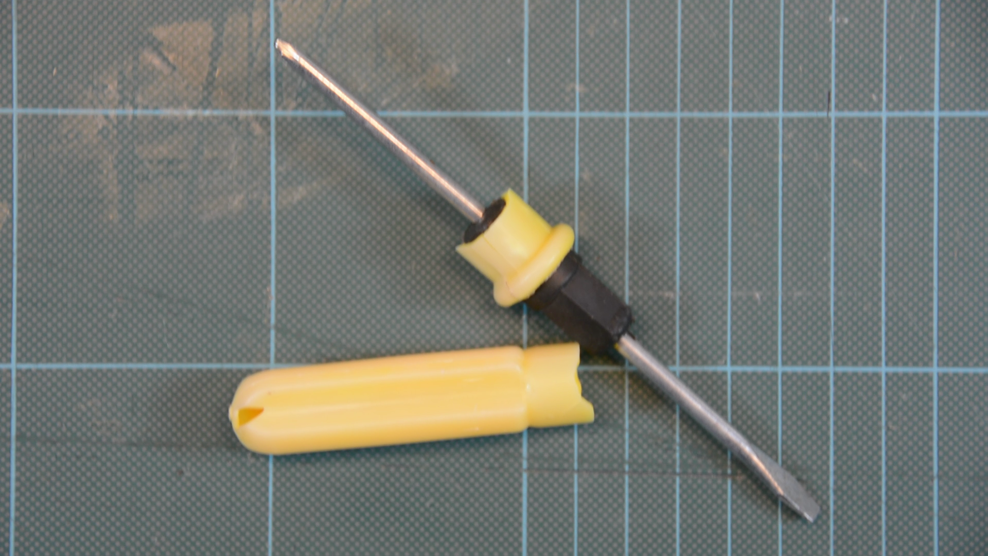
When the slot is too wide the ruler will not be perpendicular to the workpiece. I found that adding 0.3 mm to the width results in a very snug fit on my CR-10. Even with these settings I had to press really hard or secure the ruler in a vice and give the print a few taps with a screw driver handle. Pro tip: If you break the screw driver handle by pounding on the print the fit might be a bit too snug.
For the thickness of the ruler I add the same amount of play and increase it from 0.6 to 0.9 mm.

If there is too little play the ruler will catch layers from the print in the opening and damage the print.
The nail as an axis
The last parameter is the diameter of the nail where I only added 0.15 mm allowance. If the print needs superglue in order to hold the nail in place the tolerances for the lever are most likely not going to work out.
So we can also directly aim for a press fit. If you stick the nail through the hole make sure that if slides through the side part without problems before tapping it with a hammer. Without support the side part is going to break if you hit it with a hammer.
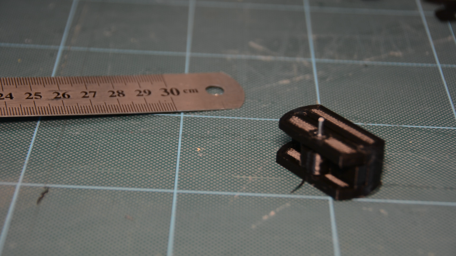
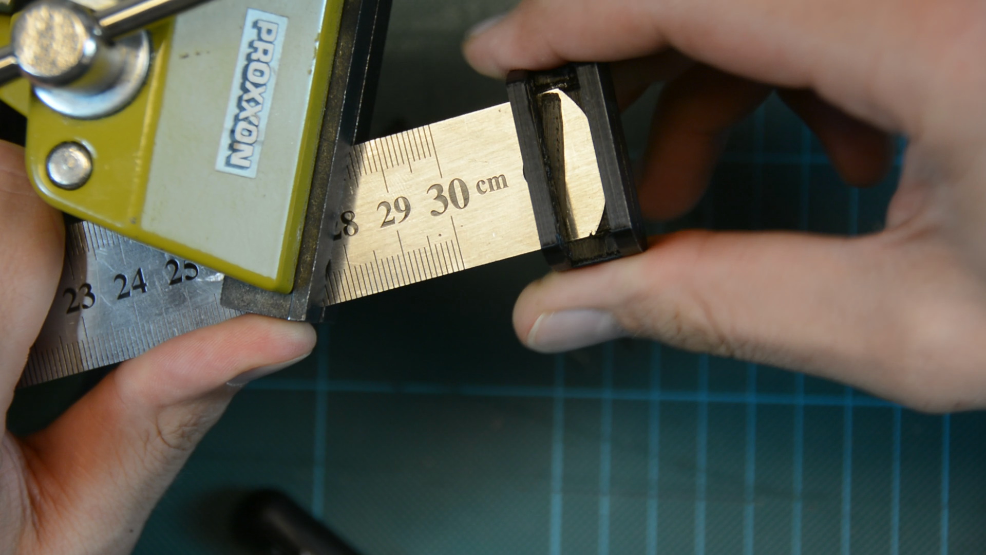
If you take all this into account you get print that slides easyly across the ruler and is securely locked in place once the lever is pushed down.