
In this article we give an overview on how we design woodworking projects in FreeCAD. The article contains quite a few fixes and workarounds that make the work with FreeCAD easier and more comfortable.
FreeCAD is an open source software that is mainly geared towards mechanical engineers. A lot of the details are clearly more oriented towards products that have few but rather complex parts – not so much a woodworking project that mainly consists out of simple boards. For a more detailed comparison of different software solutions tale a look at our CAD for makers article.
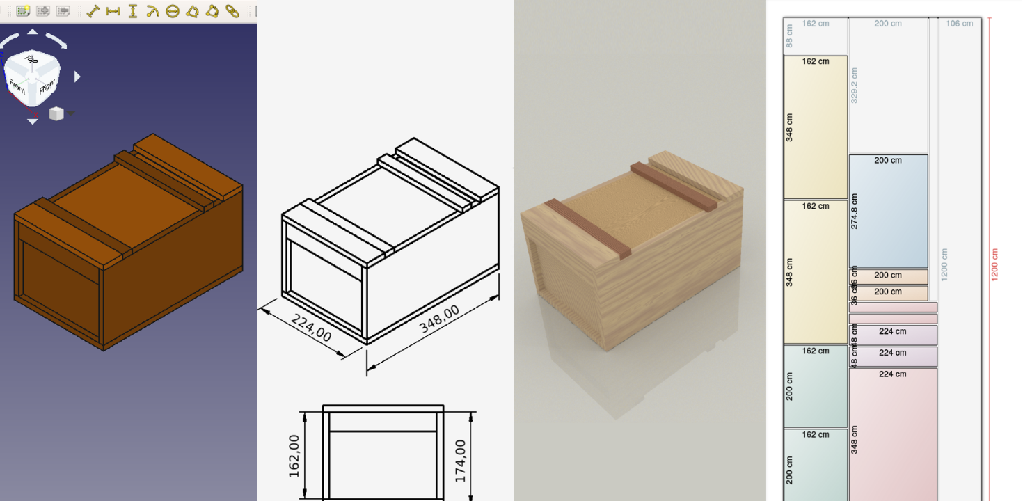
Designing a parametric Japanese Toolbox
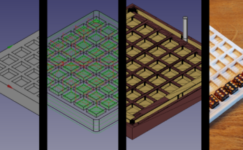
As an example we use this Japanese Toolbox design we use in a variety of sizes.

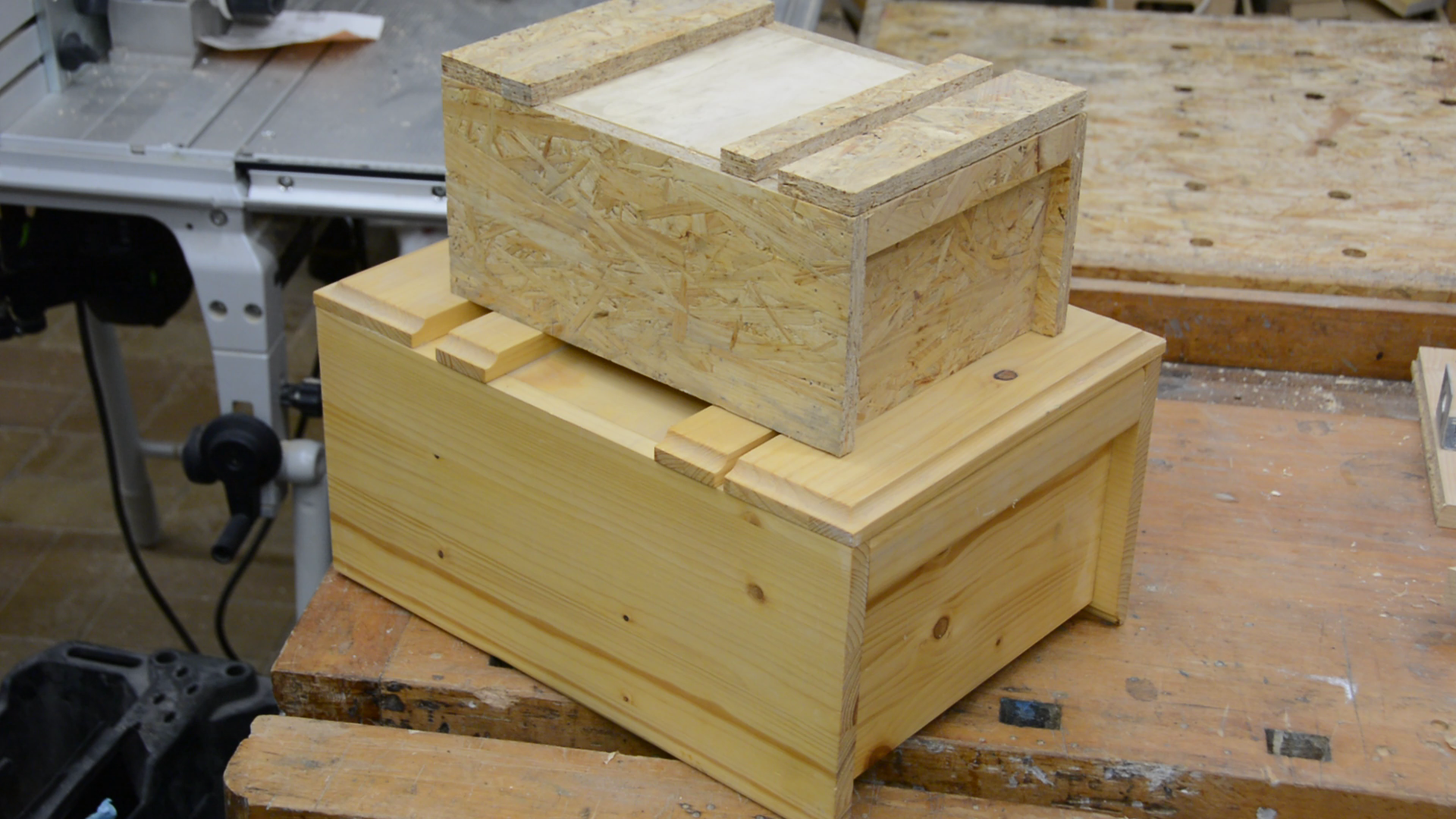
The big advantage of FreeCAD is that it is fully parametric and you can change dimensions after finishing the design. We only have to change the parameter in a spreadsheet and the box becomes square. In the same way we could also change the material thickness and create tiny boxes as well as large storage containers.
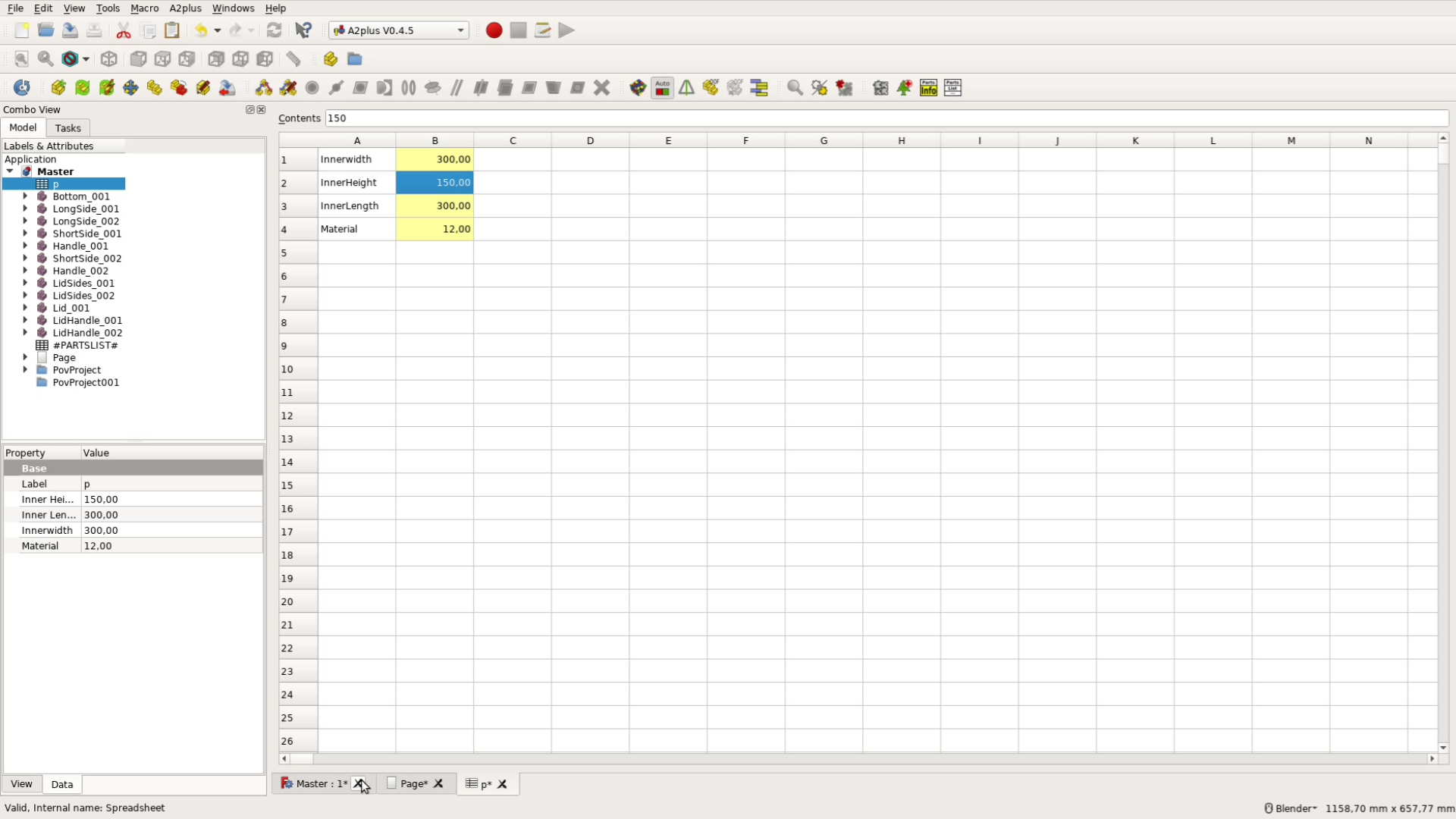

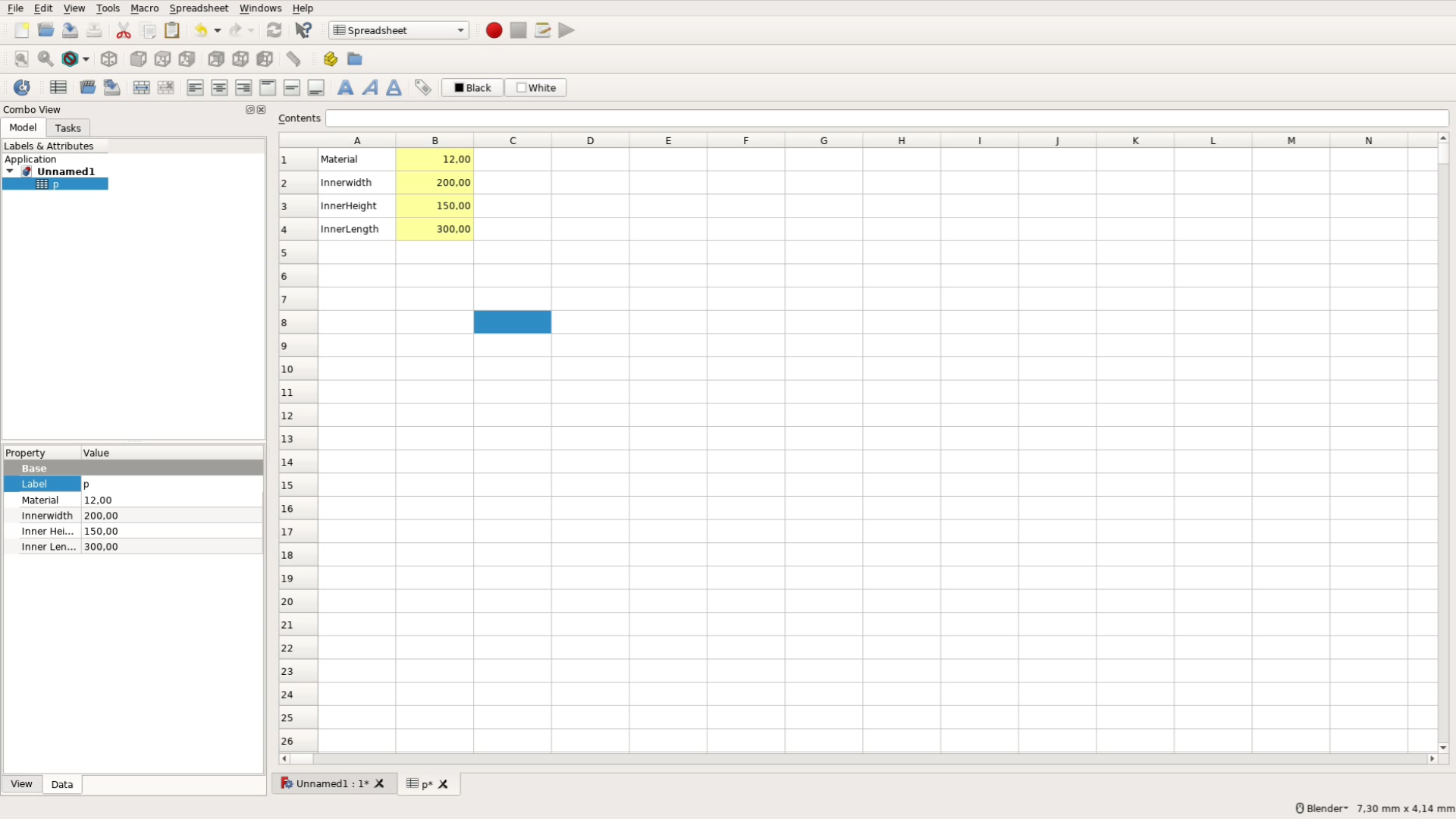
The first step is to create this spreadsheet with all the dimensions. For the box these are the material thickness, as well as the inner width, length and height. We use the Alias Manager Macro to create aliases for these numbers so that we can refer to them by name later. This Macro can be installed over the Addon Manager of FreeCAD.
Part Design
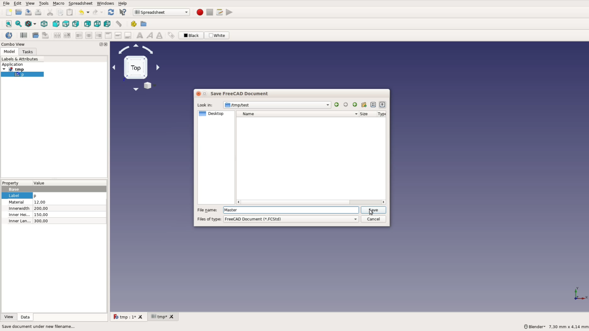
After having saved the file with the spreadsheet under the filename Master comes the part that is quite cumbersome.
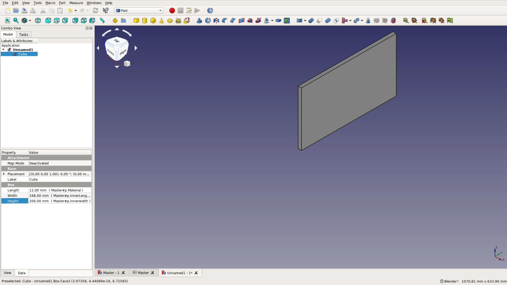
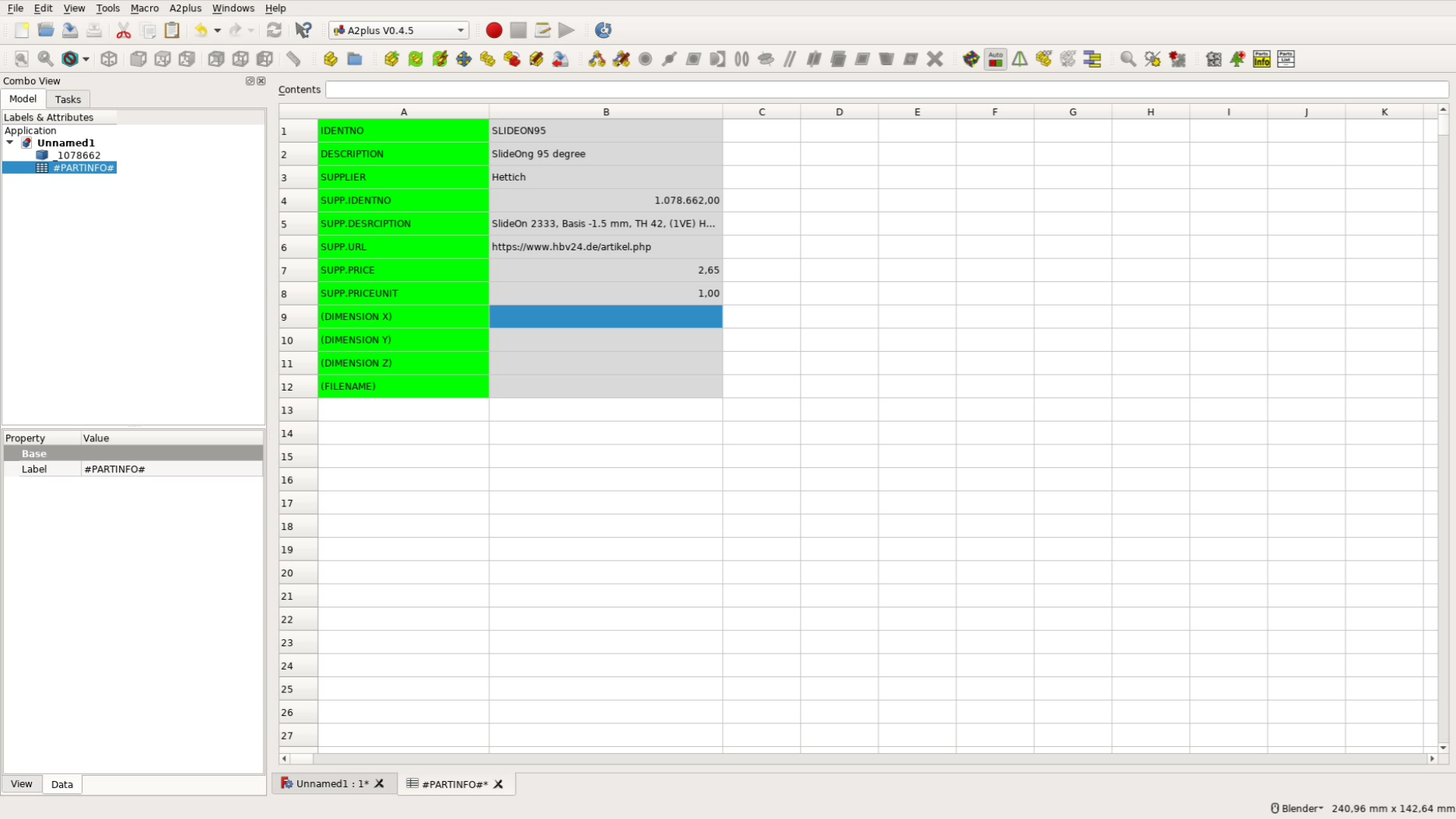
We create a new file for each individual board. In the part workbench we add a cube.
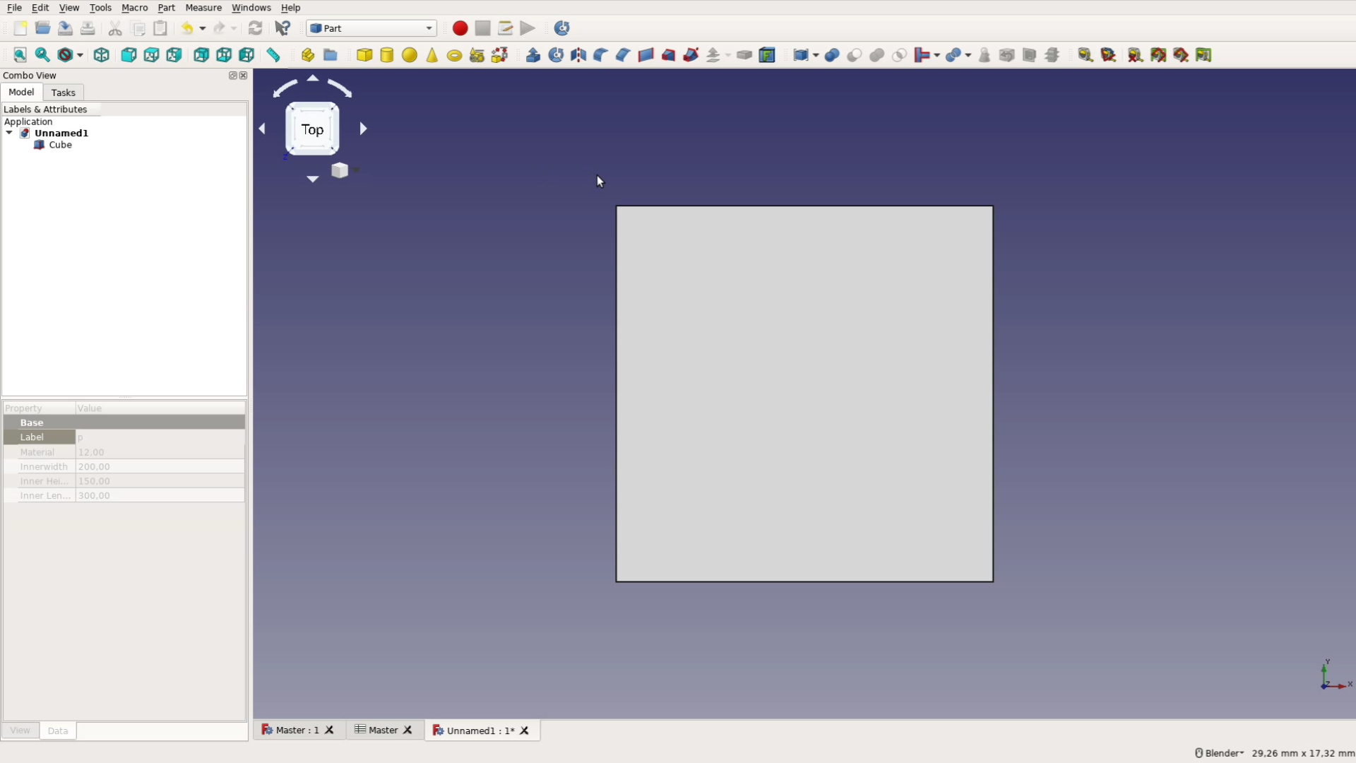
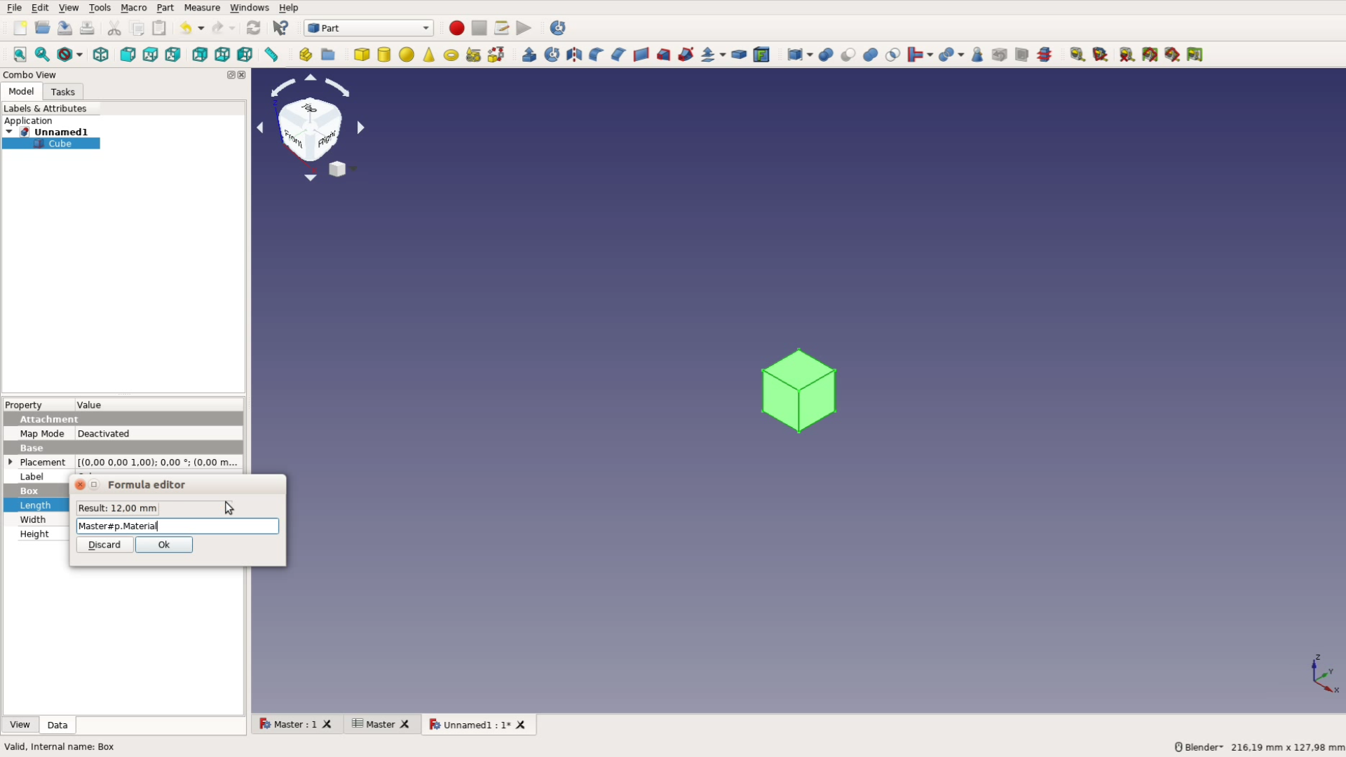
To enter a formula for the dimensions we click the blue circle. This cube gets then dimensions from the spreadsheet in the format filename, hashtag, table name, dot, variable name. This would be for example Master#p.Material.
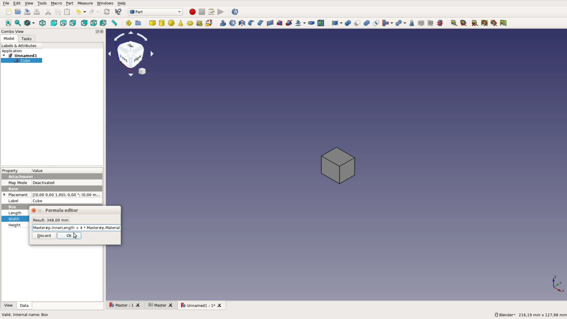
You can also perform calculations when entering the dimensions, e.g. adding four times the material thickness to the overall length.
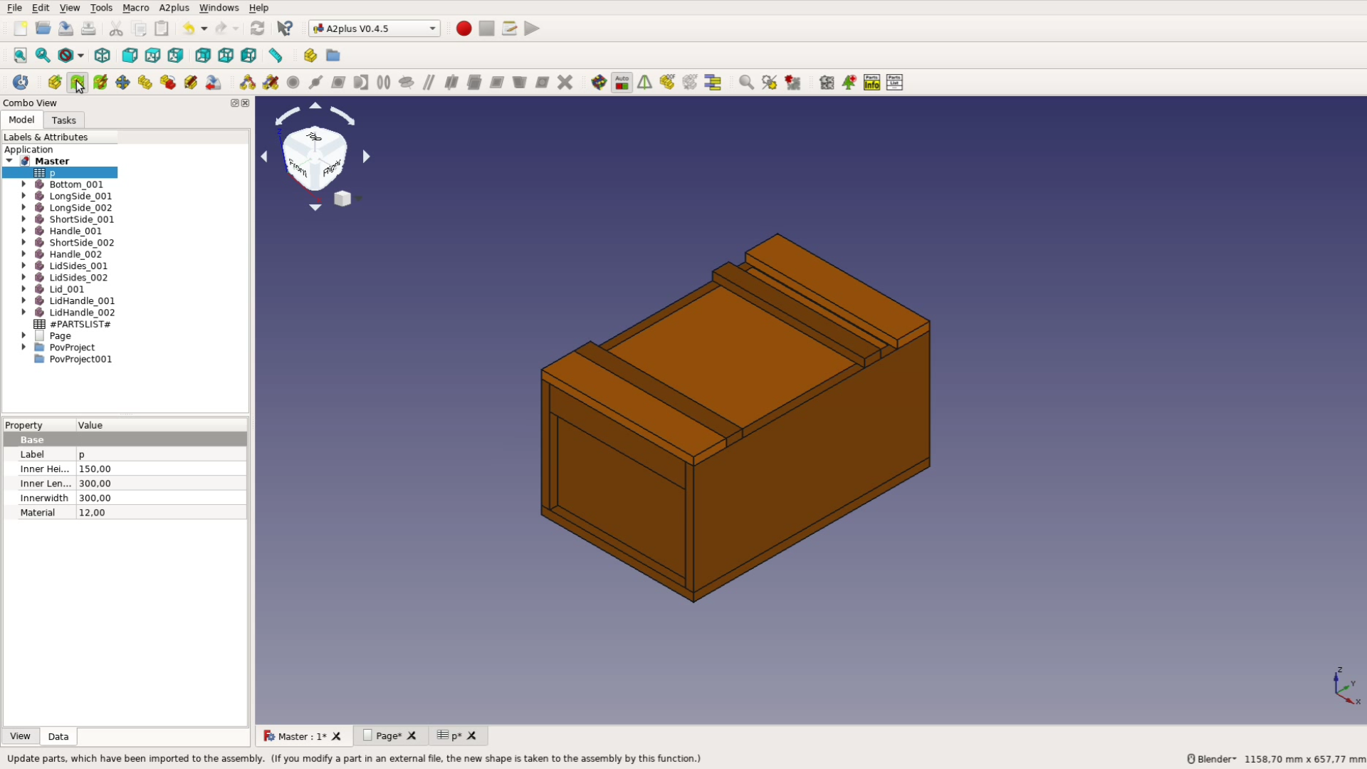
Assembly with the Assembly 2+ workbench
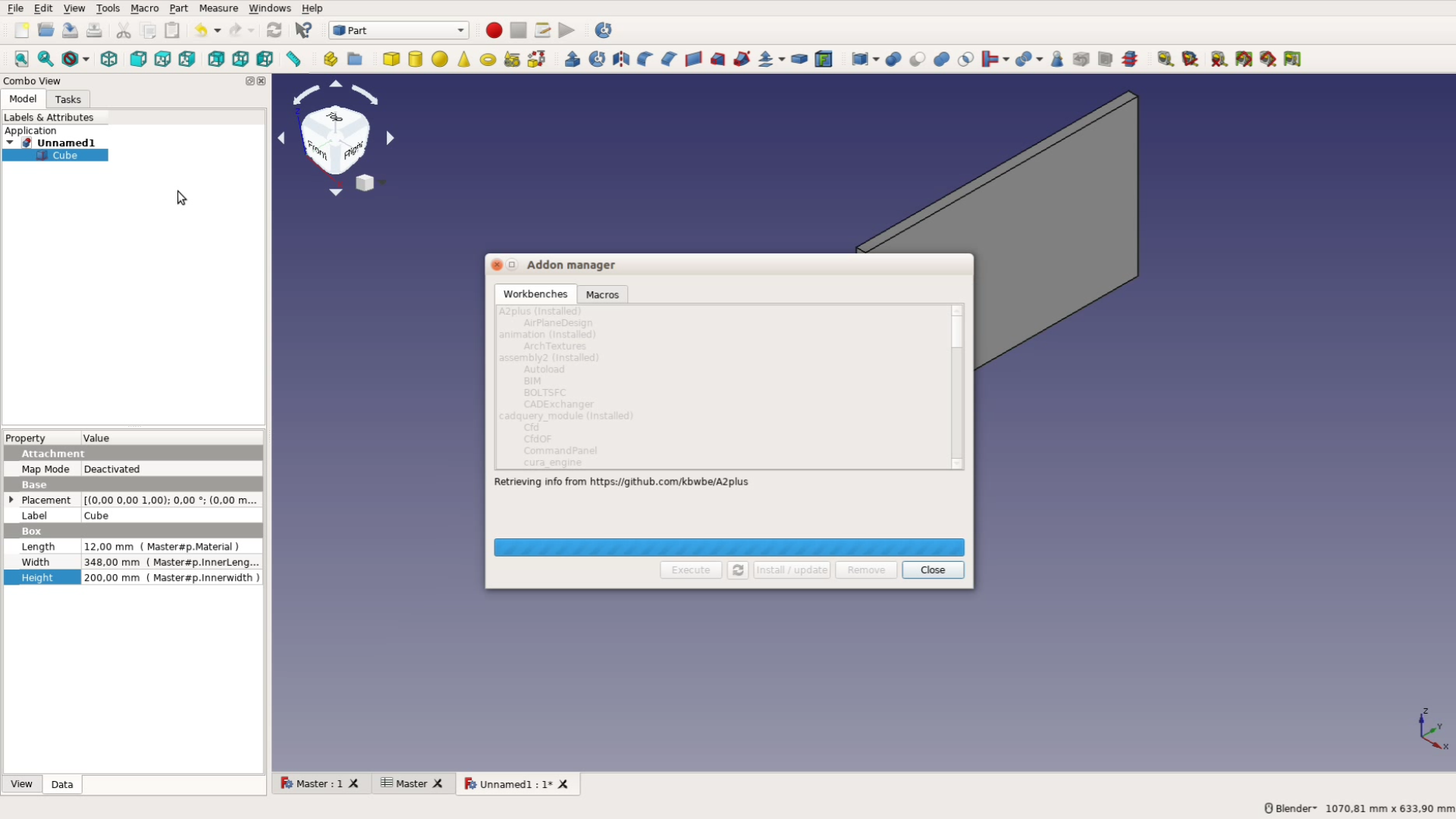
After creating all the files following the same schema we make sure the Assembly 2 plus workbench is installed. Go to Tools, Addon manager and install the latest version.
For the cutlist functionality we will discuss later you have to change two files of this addon.
First modification: In the directory where the Assembly 2+ workbench is installed (under Linux that is the directory ~/.FreeCAD/Mod/A2plus) replace the file a2p_partlistglobals.py with the one that you can download here.
Second modification: You will also have to modify the file a2p_bom.py in the same directory. Look for the following two lines in the file. In the current version these lines start at line 113:
 # last entry of partinformations is reserved for filename
partInformation[-1] = os.path.split(linkedSource)[1] #without complete path...
After these two lines paste the following code:
	    # #########################################################
            # add dimensions from the overall bounding box of the file
            # in the last 3 fields before the filename
            bb = FreeCAD.BoundBox();
            dc = FreeCAD.openDocument(linkedSource)
            for object in (dc.findObjects("Part::Feature")):
	               bb.add( object.Shape.BoundBox )
            partInformation[-2] = str(bb.ZLength)
            partInformation[-3] = str(bb.YLength)
            partInformation[-4] = str(bb.XLength)
            FreeCAD.closeDocument(dc.Label)
	    # #########################################################
This will add the dimensions of each board in the table discussed later in the article.
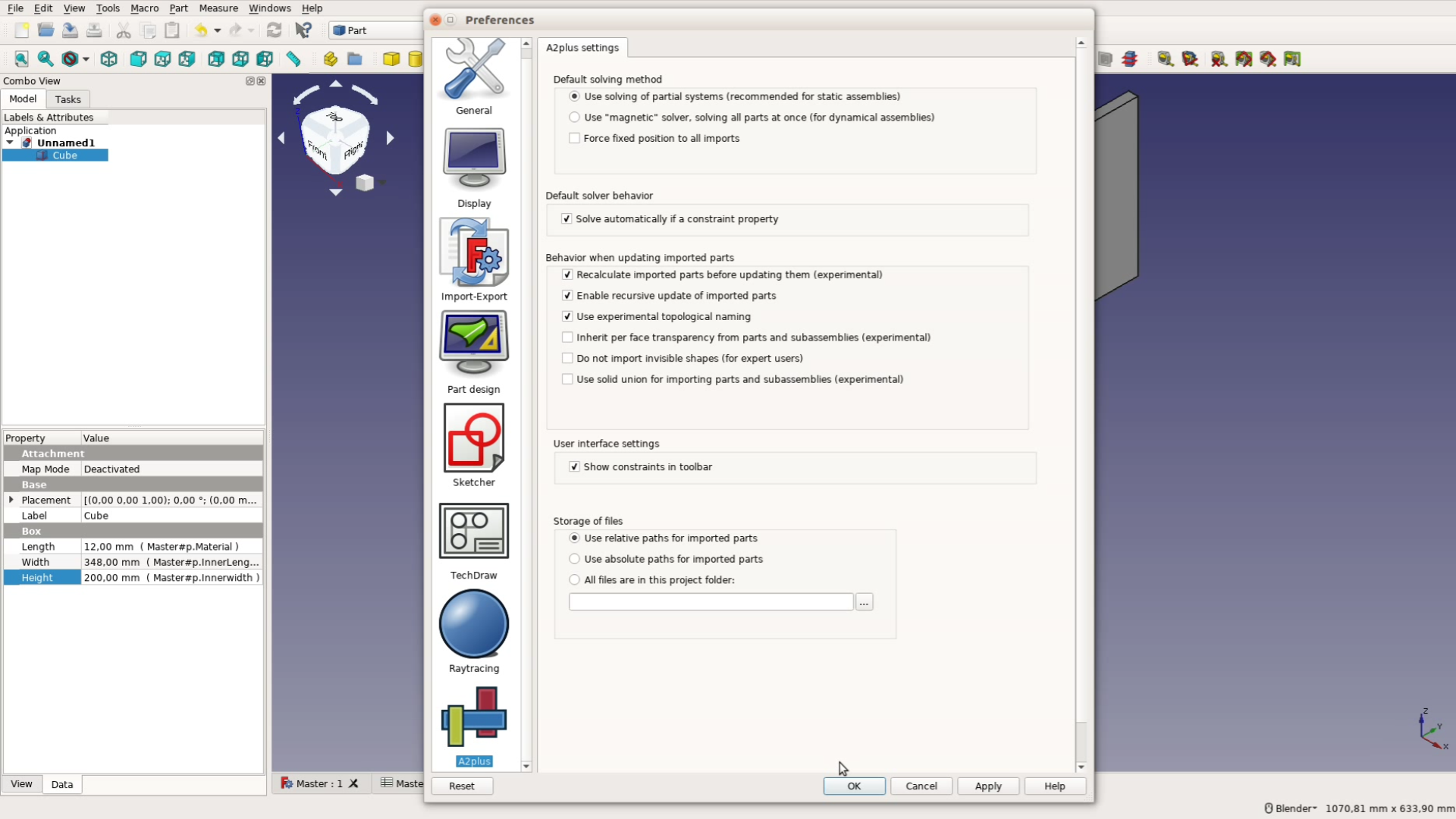
Also make sure that in Edit, Preferences, A2plus the checkboxes for “Recalculate imported parts before updating them” and “Use experimental topological naming” are enabled.
After switching to the A2plus workbench we can now import the individual parts one by one with the button that shows a plus sign . These parts can be aligned with one another in a variety of ways.
For woodworking projects most of the assemblies can be solved by making planes coincident.
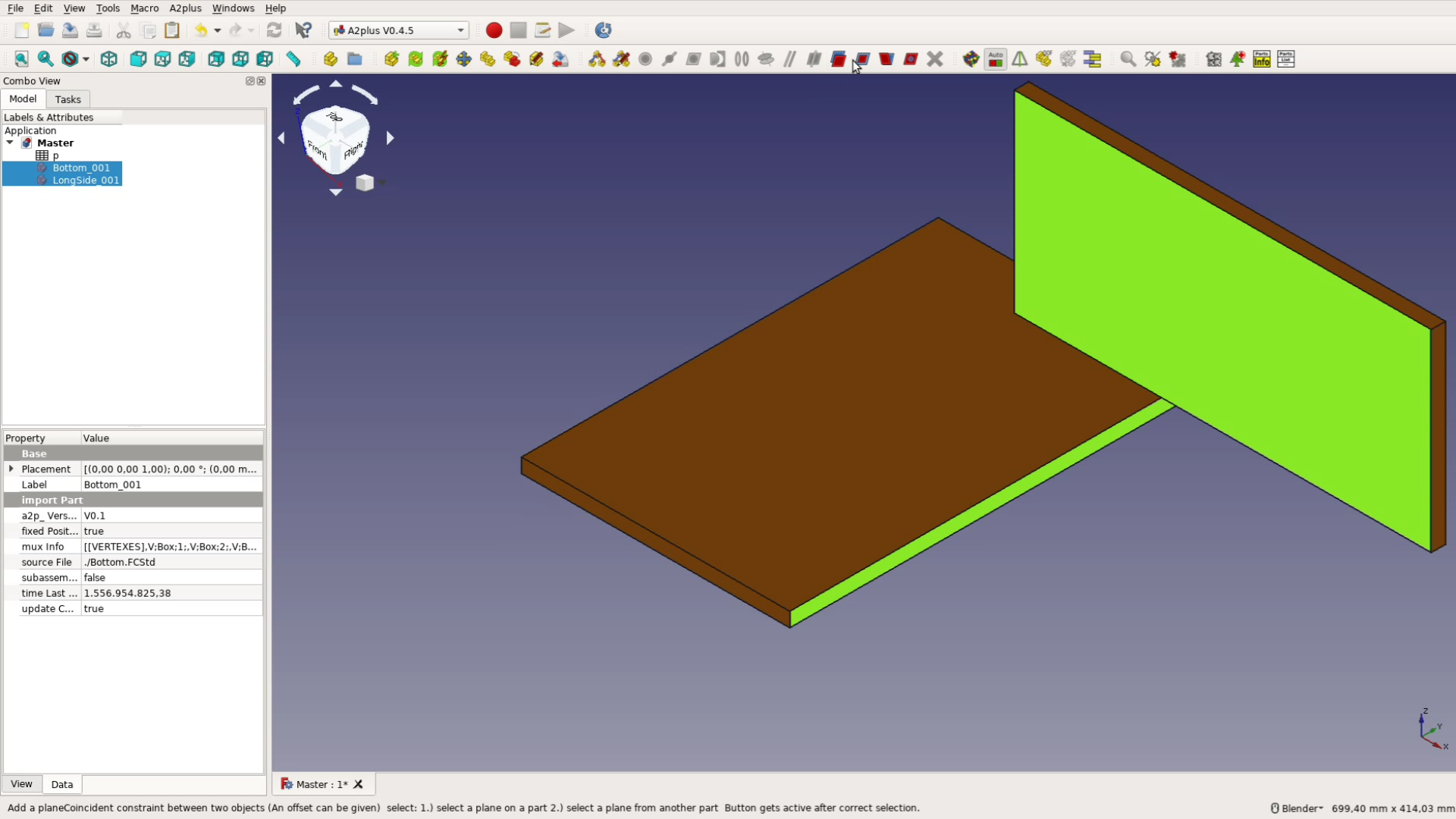
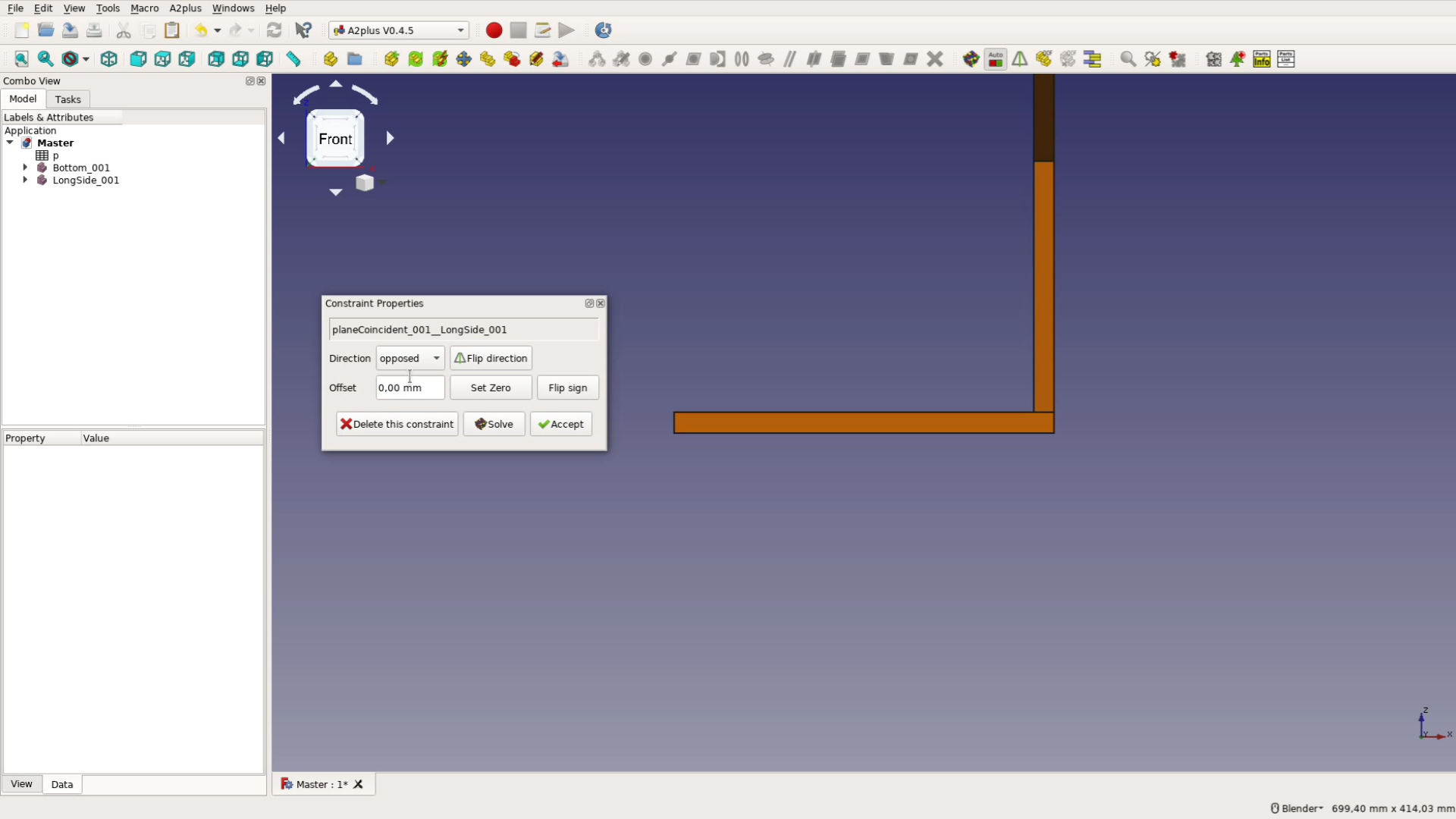
Just select two faces that you want to align, click on the plane coincidence button and decide if the two objects are opposed or aligned with one another.

After aligning three faces a board is locked in place. Assembling a project this way is fast and actually quite fun.
Creating a Cutlist
After everything is assembled we create a cutlist with the part list button. If the dimensions are not listed please modify the A2plus workbench as described above.
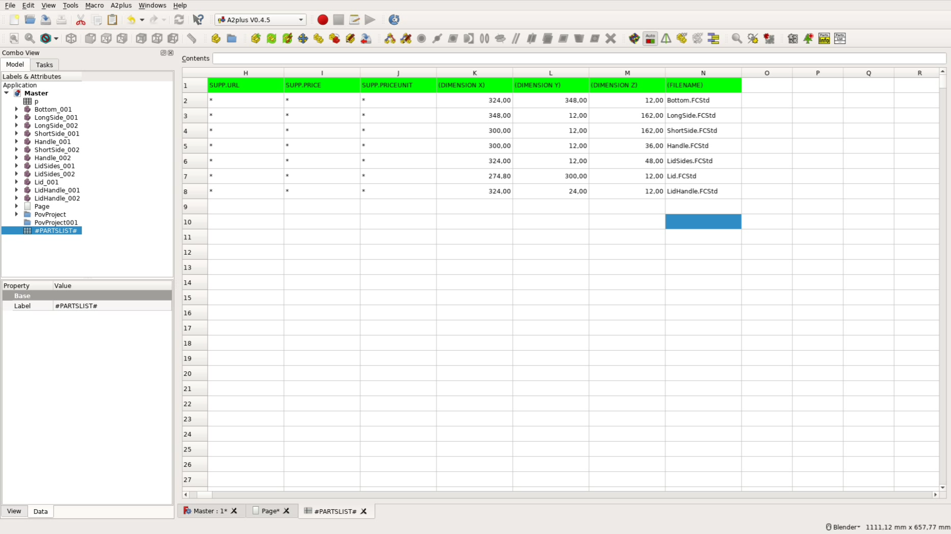
We import the cutlist in libreoffice so that it is easy to calculate square footage, price, weight and other data.
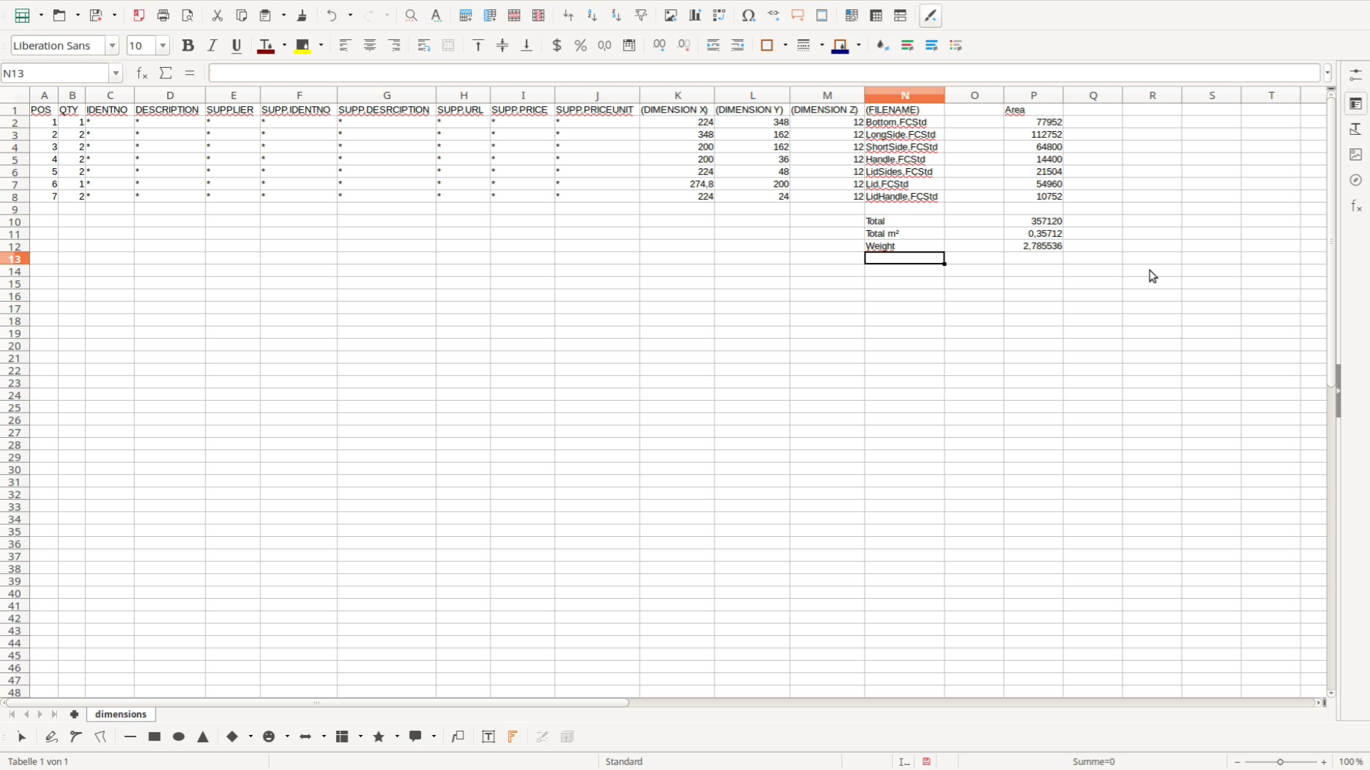
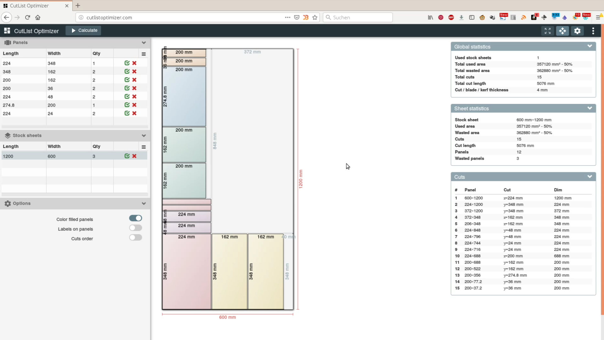
You can also export the data to another software such as Cut List Optimizer, a free (but not open source) optimization program that helps you to optimize sheet good usage.
When we use hardware such as hinges or knobs for a project we add information about a part directly in the cad file. To do so just select the part info button from the assembly 2 plus workbench and you can add various information.
All this information will at the end show up in the part list and makes cost calculations and ordering parts easy and convenient.
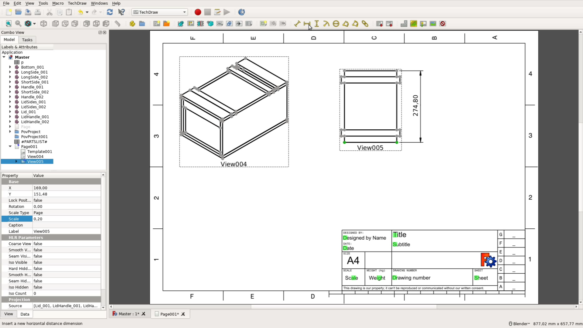
Creating a drawing
Besides the cutlist a drawing is quite helpful when building the final piece. In the TechDraw workbench we create a new drawing and are now free to insert different views.
We can also select only part of the assembly as for example the lid and generate a drawing of only these elements.
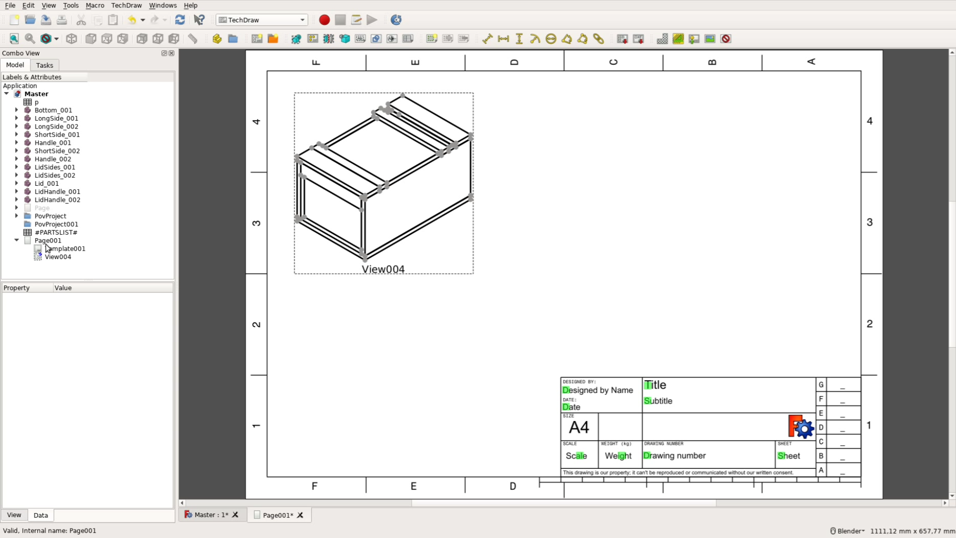
We scale them and add measurements that will help us when assembling the parts.
Rendering the object
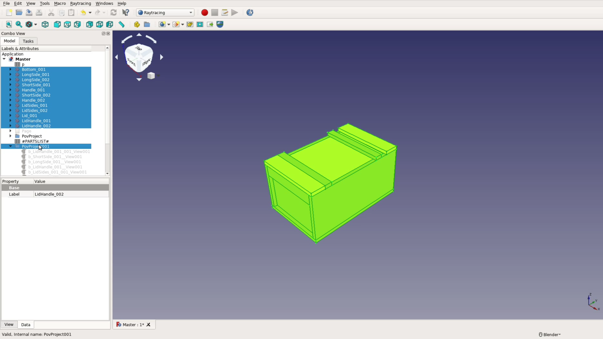
Sometimes it’s nice to get a better visualization than what the CAD application can offer. With a few clicks we change to the raytracing workbench, add a new povray project and add our objects to that rendering.
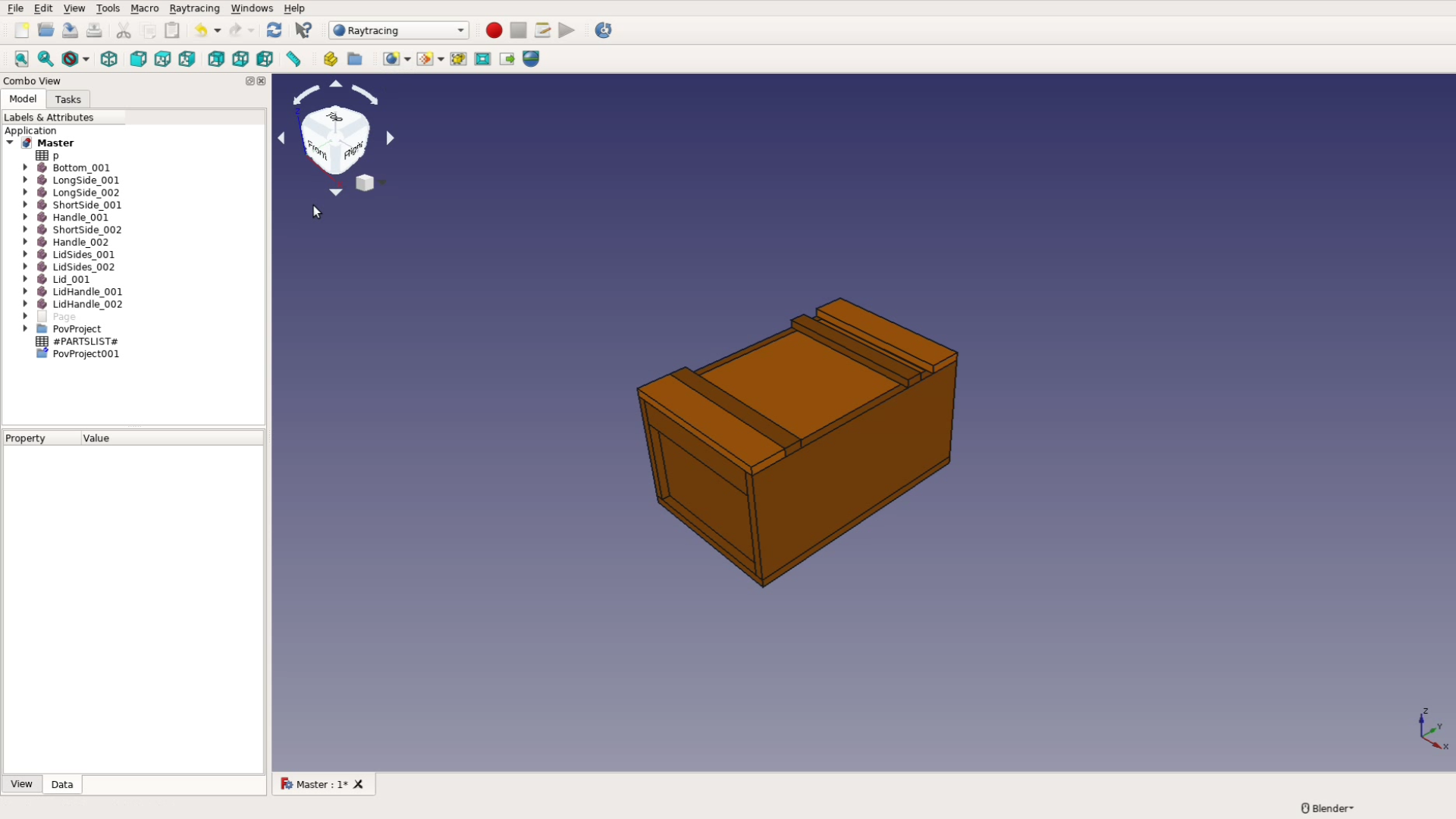
With the default settings the rendering looks bad as it is missing any texture.
In the following we describe how to use a different template file and how to fine tune the result so that it looks like this picture:
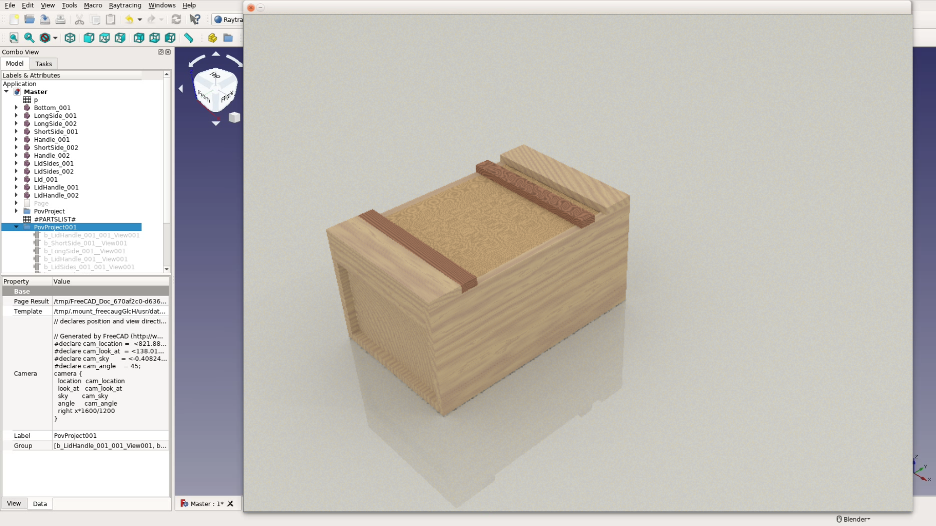
Optimizing povray renderings in FreeCAD
We start with downloading a few files that will help us improving the rendering quality:
- Download the file WayofWood.pov and save it in the directory ~/.FreeCAD/data/Mod/Raytracing/Templates
- Download the Python script texturepov.py and save it somewhere on your local machine
- Download the Colormatching PDF and print it as a reference
In order to create a nice looking rendering quickly just follow these steps:
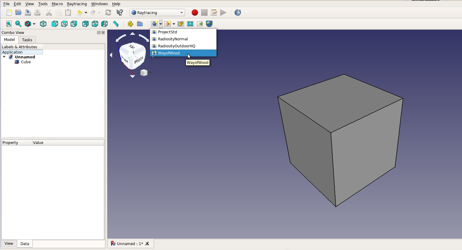
Create a new cube withe the Part workbench, then switch to the Raytracing workbench and select the new WayofWood Template:
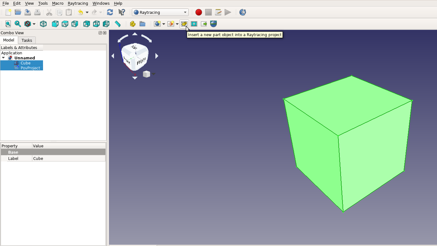
Next select the cube and the povray object and use the button with the yellow square to add the cube to the rendering:
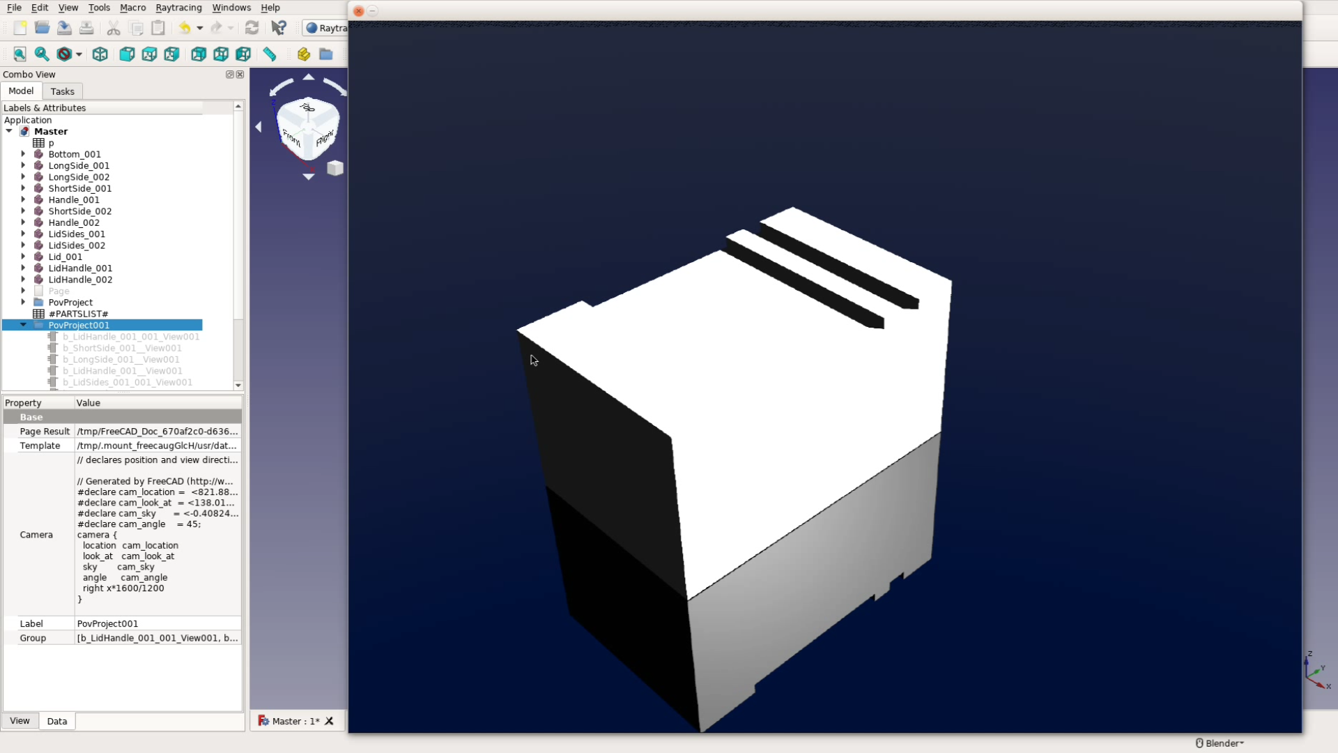
When you now hit the blue rendering button you get already a nice white cube sitting on the floor:

Click the cube view object within the povray project (not the one in the main part) and select one of the colors that are shown in the color match PDF. It’s important that you select the identical color as shown in the PDF. As an example we select magenta. Rendering the image again should result in a cube like this:

We can further improve this cube image by saving the povray file to the disk with this icon: ![]() to a file test.pov. We open the command prompt go to the directory where the file is stored and type:
to a file test.pov. We open the command prompt go to the directory where the file is stored and type:
$ python texturepov.py test.pov > test2.pov
$ povray test2.pov
This provides already a nice visualization without fiddling too much with the povray file:

By using other colors in the file you can easily create other wood textures. These renderings are not perfect but the povray files offer you the possibility to tweak them in detail, change the textures or add additional objects.
Under Linux you could go even one step further and create that little shell script:
#!/bin/bash
python ~/bin/texturepov.py "${@: -1}" > /tmp/povwrap.tmp 2>/tmp/povwrap.err
cp /tmp/povwrap.tmp "${@: -1}"
/usr/bin/povray "$@"
Then just replace the povray executable in Edit -> Preference by this script and you get textured renderings right within FreeCAD.
Summary
Desining for woodworking with FreeCAD is not ideal. The assembly of the parts is cumbersome and it’s not convenient to distribute the parts among several files. The cutlist functionality is working with the hacks described above but it’s a bit tricky to use.
But for the assembly as for the rendering: The great advantage of an open source solution is that one can modify everything and add new features. Maybe you also give FreeCAD a try and let us know what you think about it.

Hi! I’ve known about your site from YouTube.
Great possibilities! Thanks for your good work! I think it has a great potential///
I’d like to ask something:
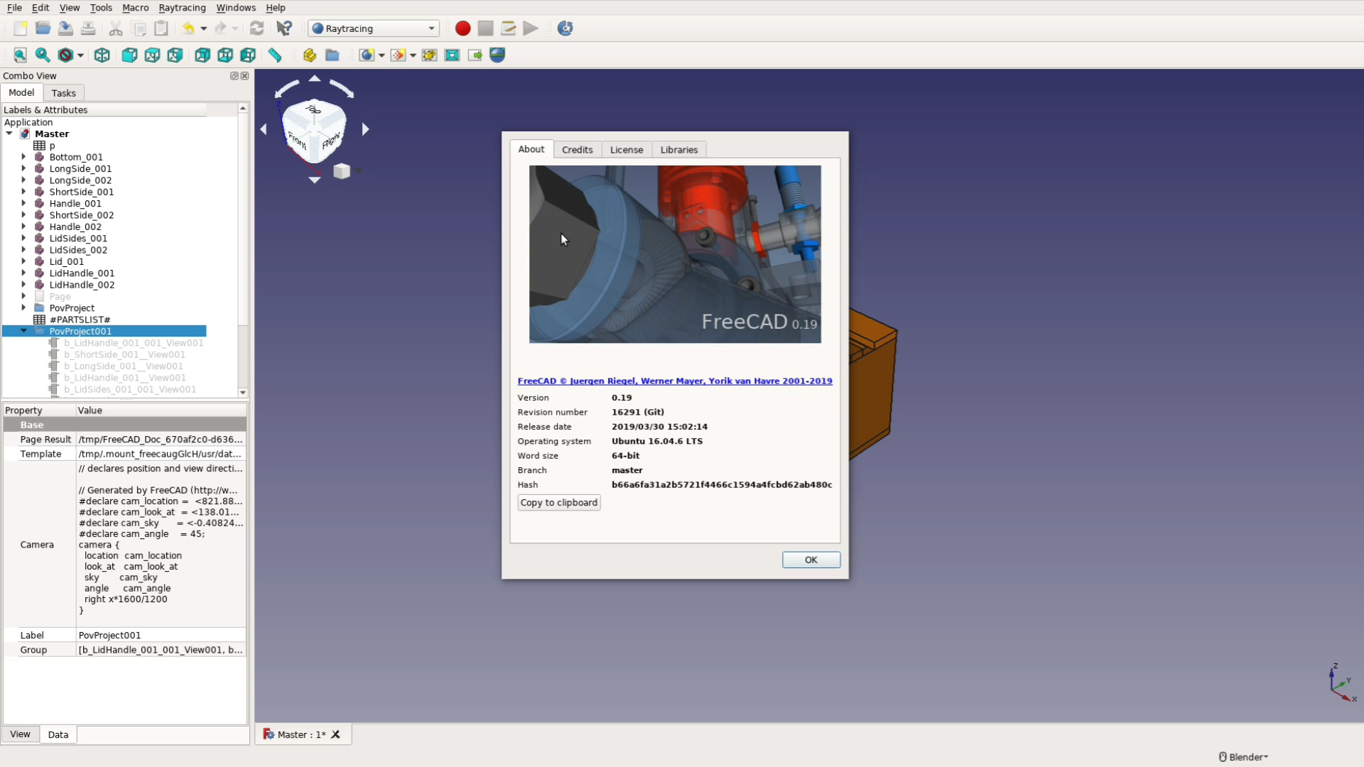
In the video you’re using a 0.19 version of FCad, which is not released. Does this stuff work in 0.18 version (which is officially released)?
Because I try to use v.0.18 (from Addon Manager I’ve installed A2Plus v.0.4.24). I’ve replaced the file “a2p_partlistglobals.py” in the directory ~/.FreeCAD/Mod/A2plus) and modified “a2p_bom.py” file as you advice.
Everything was working until the making Part List:
When I answered “Please save before generating a parts list! Save now ?” – Yes
And then “Do you want to iterate recursively over all included subassemblies?” – Yes
I’ve got the first part opened and the Report view message:
Running the Python command ‘a2p_CreatePartlist’ failed:
Traceback (most recent call last):
File “/home/cooltehno/.FreeCAD/Mod/A2plus/a2p_bom.py”, line 221, in Activated
recursive=subAssyRecursion
File “/home/cooltehno/.FreeCAD/Mod/A2plus/a2p_bom.py”, line 131, in createPartList
FreeCAD.closeDocument(dc.Label)
Unknown document ‘1’
How could I get the proper Free Cad version, if the reason is version? How this kind of stuff could be possible in the real production – are there any recommendations?
Great thanks again!
Does the A2plus workbench work when you don‘t modify it? So if you install then adding, don‘t do the modifications: Can you save two parts in two different files, import them into a new file and align them using the A2p workbench?
For the benefit of anyone else coming here to find where to download v0.19 of FreeCAD
that version is expected to be released by 31st December 2019.
Until it is officially released go to the downloads page.
Below the Current Stable Release it talks about Development Versions with a link button to the “FreeCAD releases page”. Click on the button.
Now in Github scroll down until you reach the 0.19_pre section. Look at the instructions about Click on the blue link with that title to be taken to the various releases – download the appropriate latest release for your operating system following the instructions given. IGNORE the link to Master.zip as this is a non-compiled version.
If necessary extract the dmg (MacOSX ) or 7z (Windows) then, as the instructions state, simply run the FreeCAD.exe executable from the bin directory.
Thanks for the explanation!
Welcome.
And thank you for the tutorial.
I also now have a question.
Neither a2p_partlistglobals.py nor a2p_bom.py appear to be a part of the Windows A2Plus Workbench installation, at least in the 17877 Revision of 24th August 2019.
I shall post a question on the Forum and, failing a reply, will try the tutorial without them then try to work out where they should be included and retry it with them.
Unfortunately I don’t have any Windows computer with FreeCAD installed.
Did you do a search in all your folders? Do you have other files in a A2p folder?
If the workbench is working these files should be present in some kind of subfolder where the application data sits.
Hi Paul – I was having the same problem trying to find these files on Windows 10. I finally found them in the following folder: C:\Users\[user name]\AppData\Roaming\FreeCAD\Mod\A2plus
Hello, wayofwood again! Thanks to you and to all the people for the answers!
Sorry for delayed answer…. I’ve explored the default FC v.0.18.4 (from official ppa, Ubuntu 18.04.3). Everything works fine. There was no need to correct any files or to install v.19.
Also (may be it could be interesting for you) I’ve made an exploration in detail in the FC Forum about the BOM (Bill Of Material) topic. I tried to organize “library parts” specific workflow – and I’ve known some restriction for A2Plus about the using formulas taken from the parts (not from the general spreadsheet of the assembly as in your totorial). The author of A2Plus told me that only the digits can be read from the PARTINFO(s) of the parts (not formulas).
Here’s the link to the conversation:
https://forum.freecadweb.org/viewtopic.php?f=20&t=40255
Good luck and happy FC modelling!
Good evening, see how some help you:
God bless you …
https://peertube.video/videos/watch/4ae59c2e-a926-44ee-a385-a561c23e3dda
where can i get the program freecad
nowhere to find a link to the program TO DOWNLOAD
FreeCAD download
I’ve been looking all over for the complete list of parts and their dimensions. Can you provide them or tell me where to look?
Good tutorial. A little fast if you aren’t familiar with FC.
I just posted a detailed tutorial on the box assembly that also links to a zip file with all the files for the box.
Thank for the tutorial!!.
I I’m newbee to FC. I don’t find the part list neither the post.
Can your send an direct link to the post or part list? I will appreciate it.
The files are at the end of the article in the resource section:
FreeCAD for Woodworkers: Assembly with the A2+ workbench
Hello,
I have tried to render a object described by your workflow.
However, i was not able to aply the Wood texture.
According to the workflow it is written:
We open the command prompt go to the directory where the file is stored and type:
$ python texturepov.py test.pov > test2.pov
$ povray test2.pov
Which command prompt do you mean ? The cmd.exe in Windows or the Phyton Console in freecad or the Commands Panel freecad?
The cmd.exe in Windows is what I am talking about – although to be fair I only tested it under Linux.
If you have Python and Povray installed the script should work.
The Assembly 2 workbench is listed as obsolete in FreeCad.
There is a new Assembly 4 that seems to be taking its place. I am wondering what to do about that.
I definitely want to make cut lists, and do assemblies.
Thanks so much for your insights. I have been a programmer for years. I dablled in CAD a bit, but I am just getting started.
Assembly 4 is quite attractive for woodworking tasks – especially as you can change the content of a part (think different drawer pulls).
It lacks the handy Part list feature of A2p though…
Hello,
I am working off of a Mac and am having trouble finding the Raytracing/Template folder. This doesn’t seem to work for me:
~/.FreeCAD/data/Mod/Raytracing/Templates
Any suggestions on how to find it or what it might be called?
I don’t own a Mac but according to Google it’s ~/Library/Preferences/FreeCAD/Mod/Raytracing/Templates
Thanks for the quick reply! For some reason the only things in the Mod folder are the workbenches I’ve added through the Addon (A2Plus and A4). Since Raytracing is automatically installed it doesn’t show up in the Mod folder…
Try to just create the folder manually…
Hi,
I’m using version 0.18 on Windows, and did all the steps but didn’t get that extra 3 columns of the dimensions.
Do you have any troubleshooting experience in that?
Thx
Neta
It might be that the file is in a different location in Windows. Could you search for the filenames if they are in a different place?
I sketched a 300mm by 410mm board as a part in x-z plane an extruded 18mm in y-direction. All other parts of the assembly are in x-y-plane. In parts list (0.18 from Debian repository, with A2plus v0.4.47e) bounding box entries only for the x-z-plane part were incorrect (600,410,410). After redoing the sketch in x-y-plane and extruding in z-direction parts list is now correct.
The added lines in a2b_bom.py are o.k. for all other parts, hence I suspect some problem with the code to obtain values for .ZLength, .YLength, .XLength when sketch is used in the non-default plane. I have not invesigated any further. Just want to inform you.
Thanks for letting me know!
Hello,
First, let me thank you for this tutorial, this is very instructive and you are doing great work for the Freecad community!
I have a problem when trying to render my project. Here is what povray tells me when transforming test.pov into test2.pov with texturepov.py:
File ‘test2.pov’ line 3774: Parse Error: No matching } in ‘texture’, undeclared
identifier ‘DMFWood4’ found instead
Fatal error in parser: Cannot parse input.
Render failed
I have this block in test2.pov which seems faulty:
object {Pov_Body001
texture{ DMFWood4 }
}
Do you have an idea of what to do?
Good question. Did you tried to use another color / texture?
I have the same problem. Editing the left over povray file adding include “textures.inc” under the other include lines makes povray run but the rendered png is uniform grey.
Hope that helps
Wolfi
OK, I had the same problem and the template was not applied properly to the output. If you create the povray project not by the icon but by the little arrow next to it you can directly select the template to be used. This works for me, changing the template later does not work.
Hope this helps
Wolfi
Hello,
Thank you for this tutorial, it’s very useful.
I found a bug in your algorithm to calculate the dimensions. It appears with cut object : you add the boundbox of all internal objects even the ones used to cut the final object.
I patch it but I don’t know how to send you the patch.
Didier
Cool. Thanks for letting me know. Could you please from me the change by mail (there is a catchall inbox so just send it to any mail address at wayofwood.com)
Thanks a lot!
Hello,
Did you get my patch ? Could you test it ?
Didier
I received it but I am just returning from vacations. So it might take some time for me to catch up with my backlog.
Thanks a lot!
Awesome combination of things I love: Woodworking, Linux and Open Source Software.
Hi,
I wanted to use your code for partslist. Unfortunately it doesn’t work in FreeCAD 0.20.2. I got it to run. If you are interested I can provide a patch file or the modified files.
I really appreciate your work and love to watch your videos.
cu – Thomas
P.S. Ich spreche Deutsch, falls das eure Sprache ist.
Thomas –
Would you kindly document and publish your solution for all? I think that would be most welcomed!!
I decided I needed to find and learn how to use some woodwork design software after laying out my first cabinet project in a 2D vector drawing package and discovering I had failed to take account of the dimension change for the stretcher bars when putting a dado in.
Looking for something either free, or one-off-low-cost, FreeCAD seemed to be the one of choice.
FreeCAD-0.21.2.33771 installed on MacOS.
Installing A2plus and creating a parts list didn’t work. The spreadsheet was empty. (But the instructions I found did not mention importing parts and making planes coincident that yours says to do…. – Could that be the reason it didn’t work?)
Then I found your tutorial and swapped out a2p_partlistglobals.py and made the additions to a2p_bom.py.
When I switch to A2plus, I get the error message below.
Changing reference in a2p_partlistglobals.py from ‘PARTLIST_COLUMN_NAMES’ to ‘CLO_PARTLIST_COLUMN_NAMES’ just changed the error message to say it then could not find ‘PARTLIST_COLUMN_NAMES’
No idea what to do now.
The whole reason was to find software to easily design woodwork projects and create parts lists / cut lists.
Can you suggest how to get FreeCAD to work for me, or if there is a more suitable [working] software I could use?
20:16:50 Initializing A2plus Workbench v0.4.66.
20:16:50 cannot import name ‘CLO_PARTLIST_COLUMN_NAMES’ from ‘a2p_partlistglobals’ (/Users/—USER—/Library/Application Support/FreeCAD/Mod/A2plus/./a2p_partlistglobals.py)
20:16:50 Traceback (most recent call last):
File “”, line 79, in Initialize
File “/Applications/FreeCAD.app/Contents/Resources/lib/python3.10/site-packages/shiboken2/files.dir/shibokensupport/feature.py”, line 139, in _import
return original_import(name, *args, **kwargs)
File “/Users/—USER—/Library/Application Support/FreeCAD/Mod/A2plus/./a2p_BoM.py”, line 37, in
from a2p_partlistglobals import (
Another user kindly created a fix for that problem. Have a look here: https://github.com/vwildi/A2plus/tree/feature/AddCutListOptimizer