

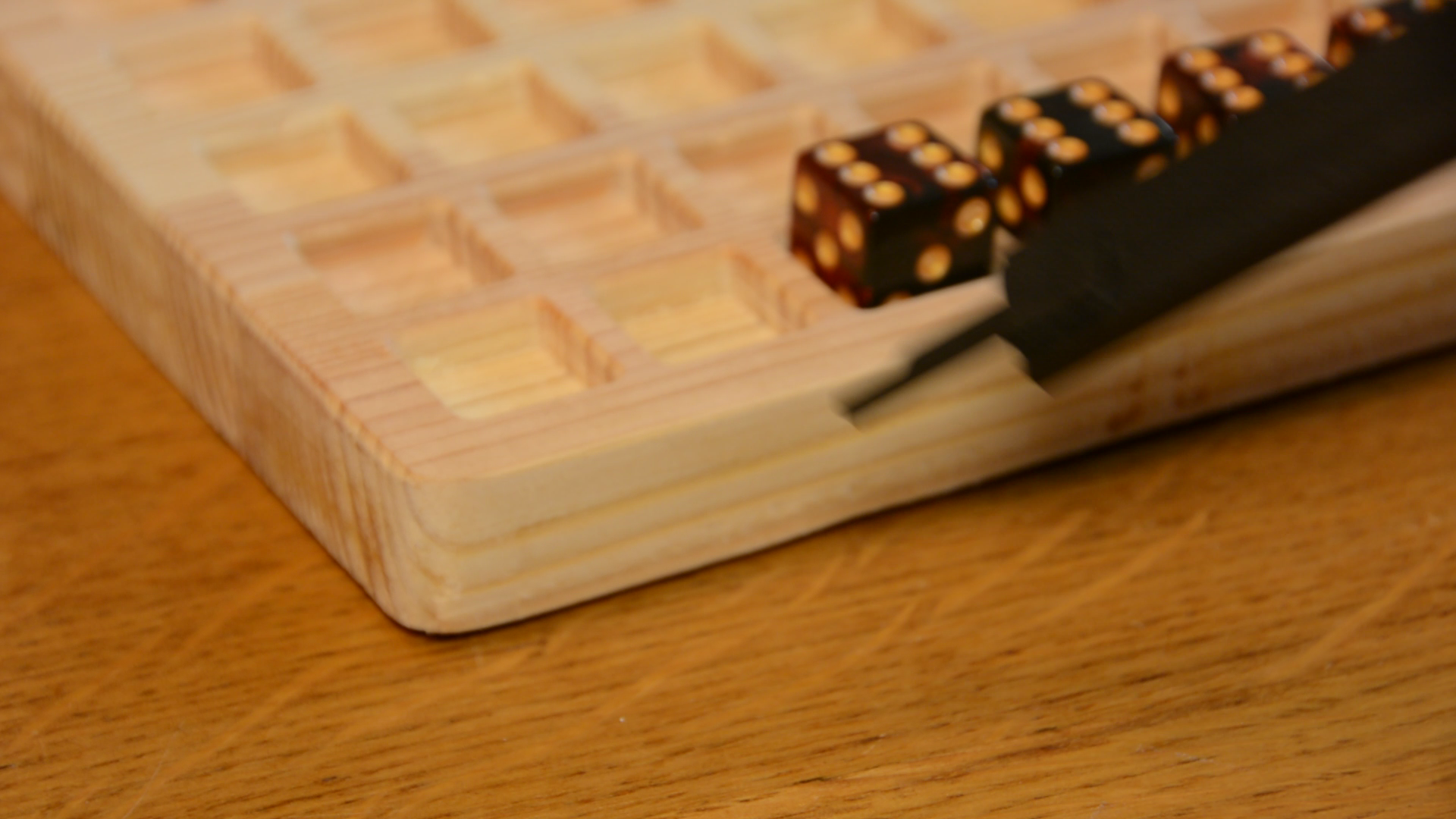
In this article , we make this simple dice game in FreeCAD, run the CAM part and cut it on the CNC machine. I recently got a new CNC – a more detailed article on the machine will follow soon.I this article I will machine this simple dice game on the CNC and go step by step through the necessary operations in FreeCAD.
Freecad CAD modeling
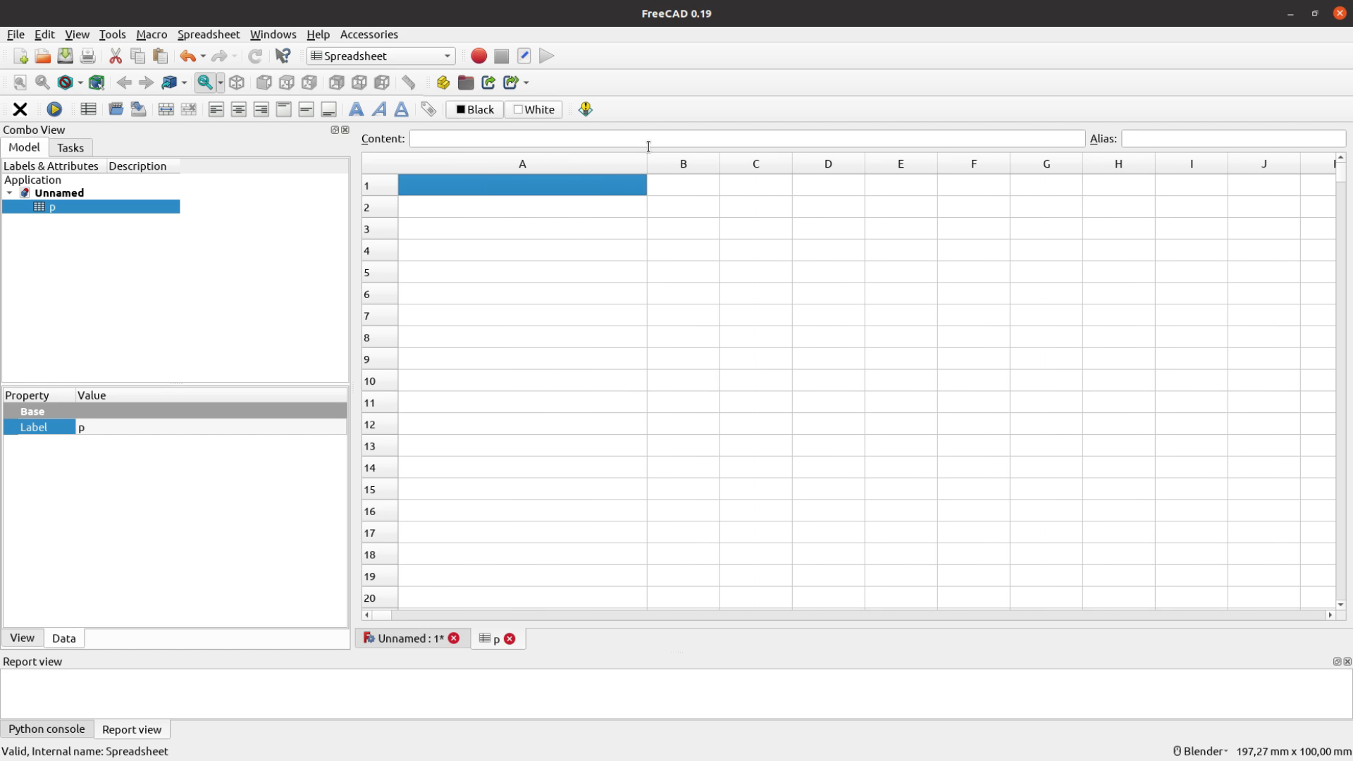
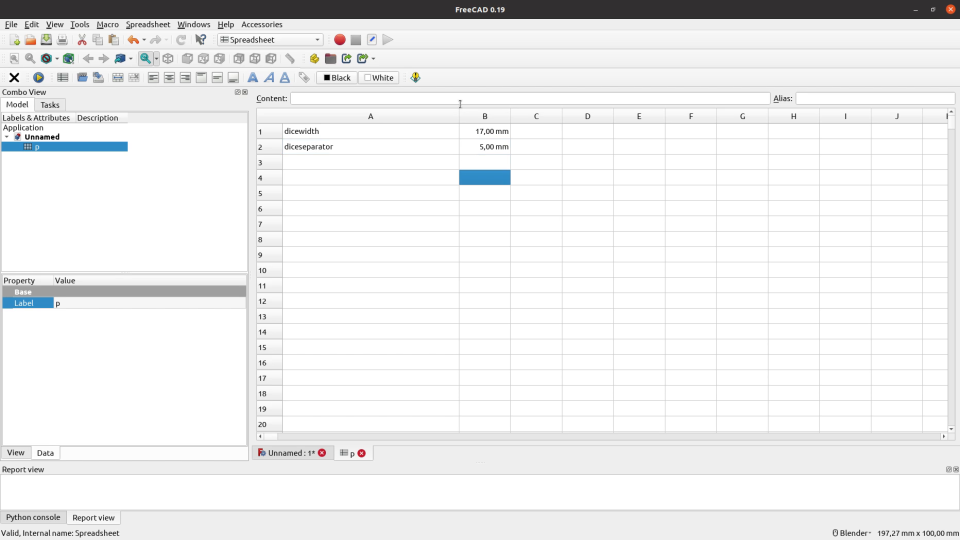
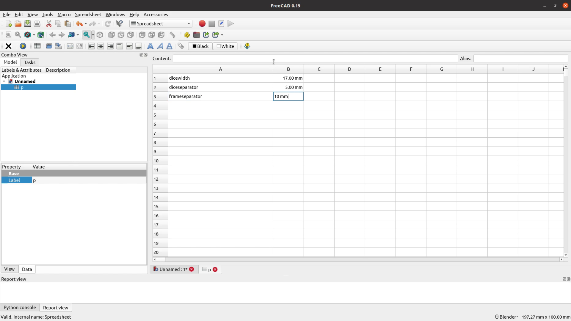
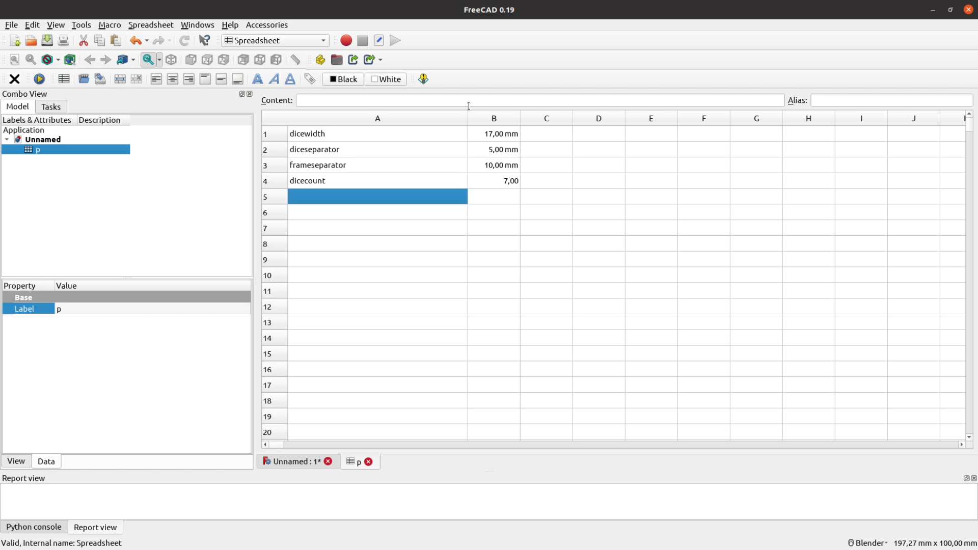
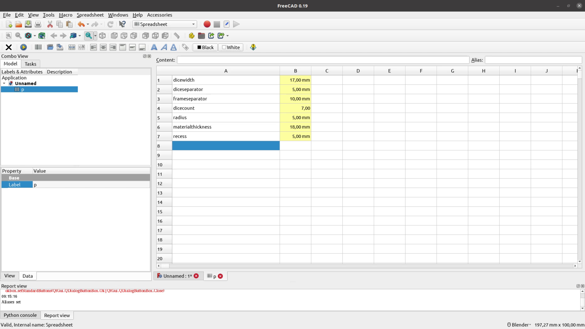
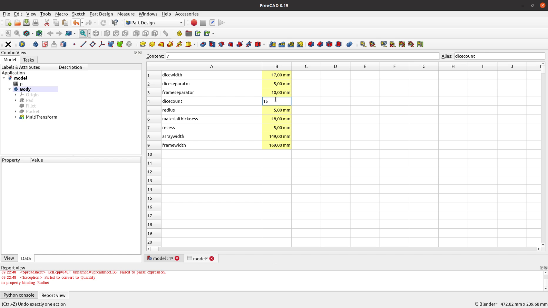
When I am modeling something in FreeCAD I always create a spreadsheet that contains all the necessary parameters – so that I can easily change these later.
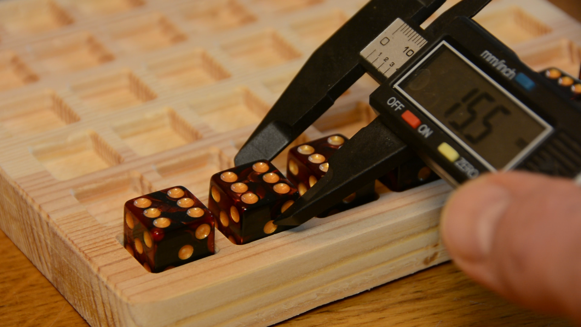
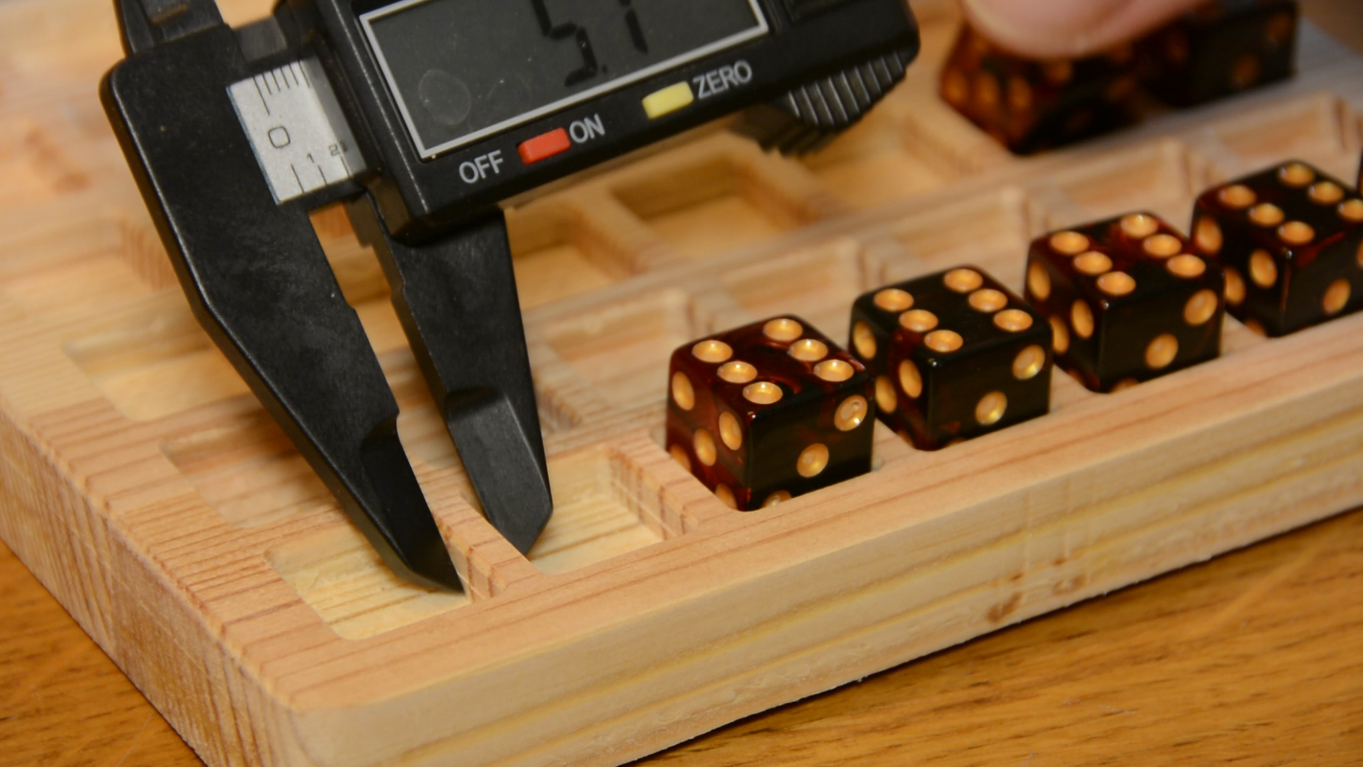
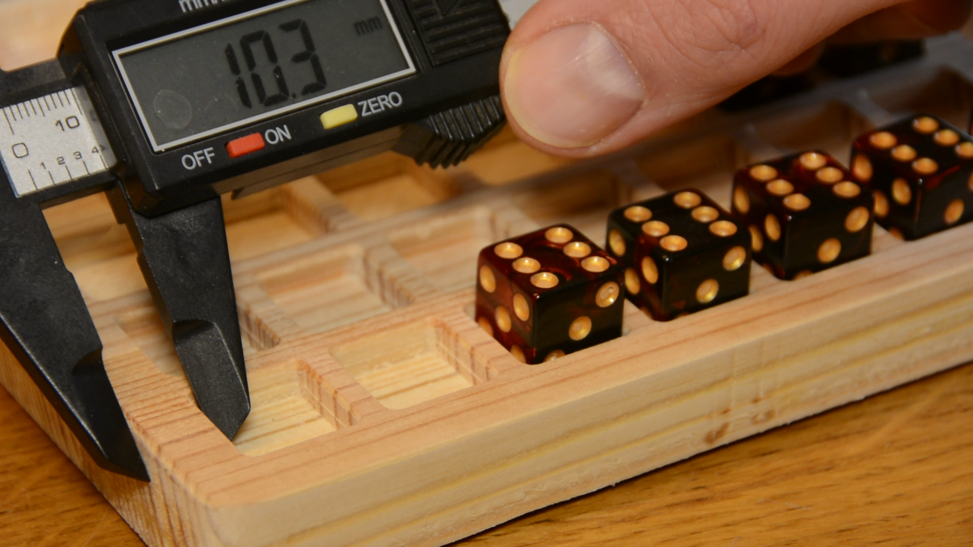
For this model we need the width of a dice, the width of the wooden separator between two dice, the width of the frame around the game, the amount of dice in one row, the radius of the corners, the thickness of the material we are going to use and the depth of the recess we create for each dice.
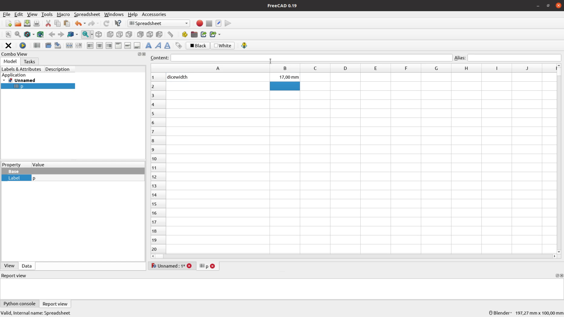

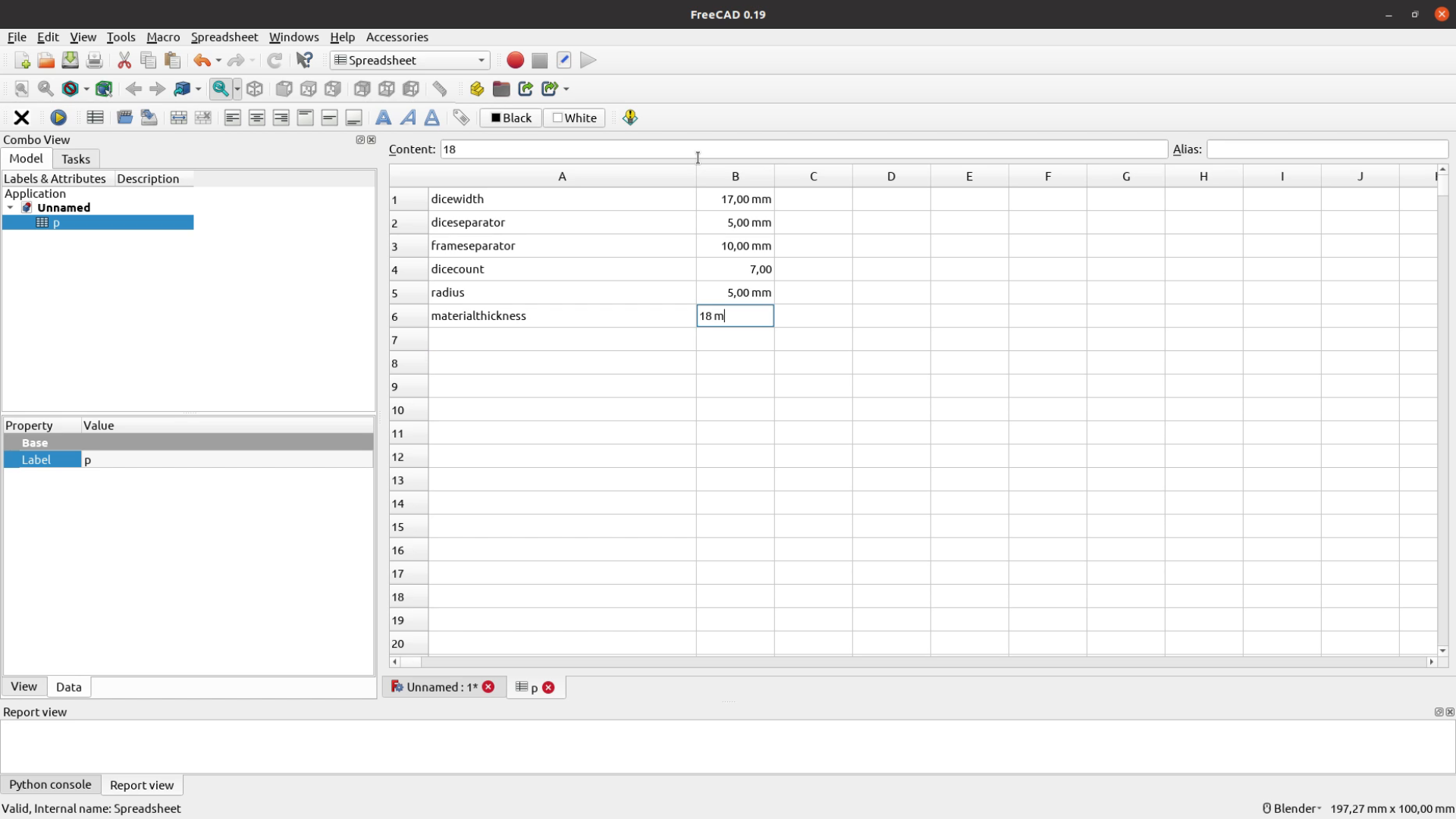

I use the alias macro to set all the aliases at once. You can install this macro in the tools menu. Have a look at this video that that explains the necessary steps in detail. After all the aliases are set we can calculate the width of the array and the width of the entire frame so that we can use these variables later in the model.

Part design
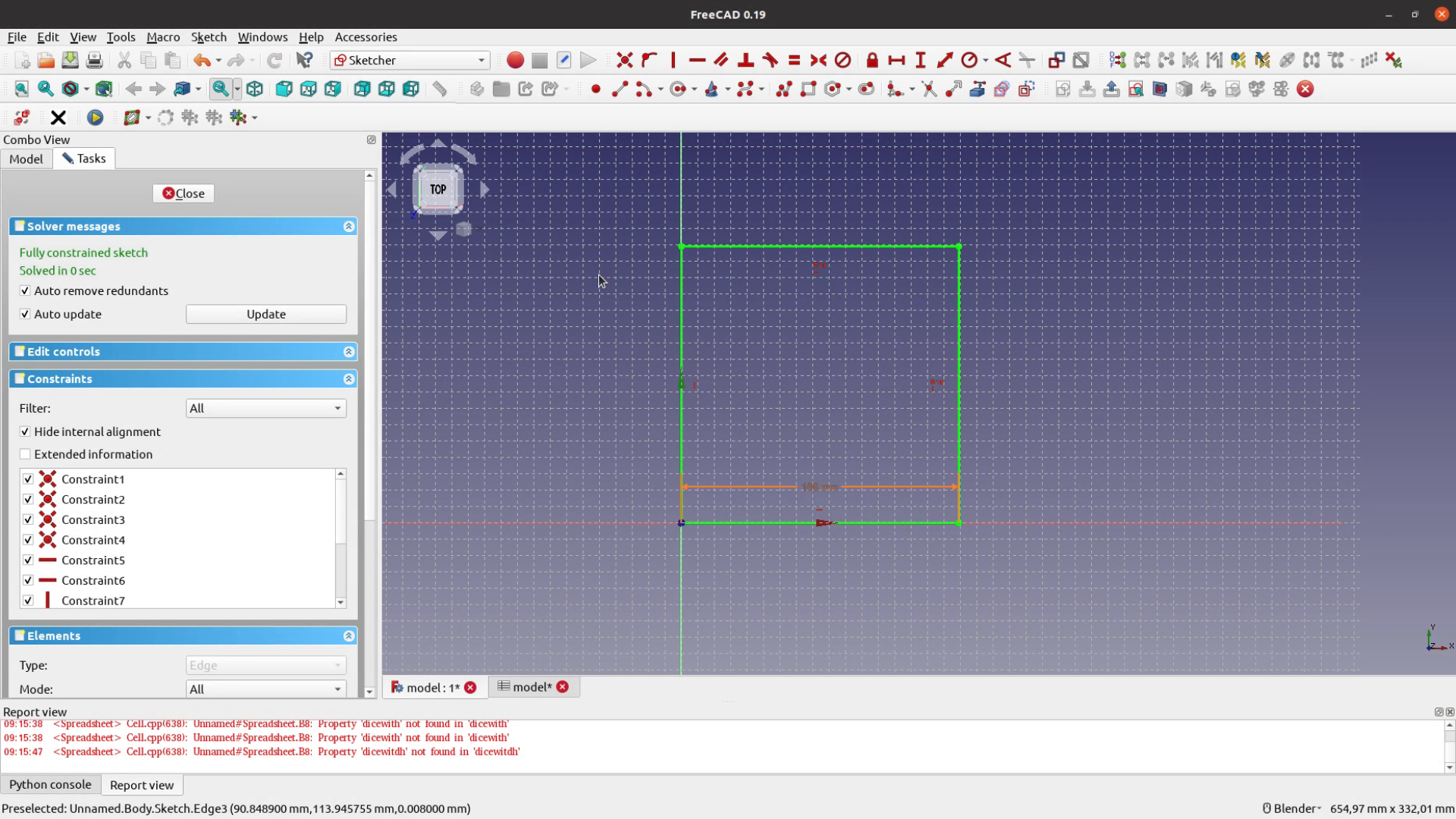
With all the dimensions set the actual modeling is quite simple. We start with a sketch in the XY plane and make the square as wide as calculated in our variable framewidth.
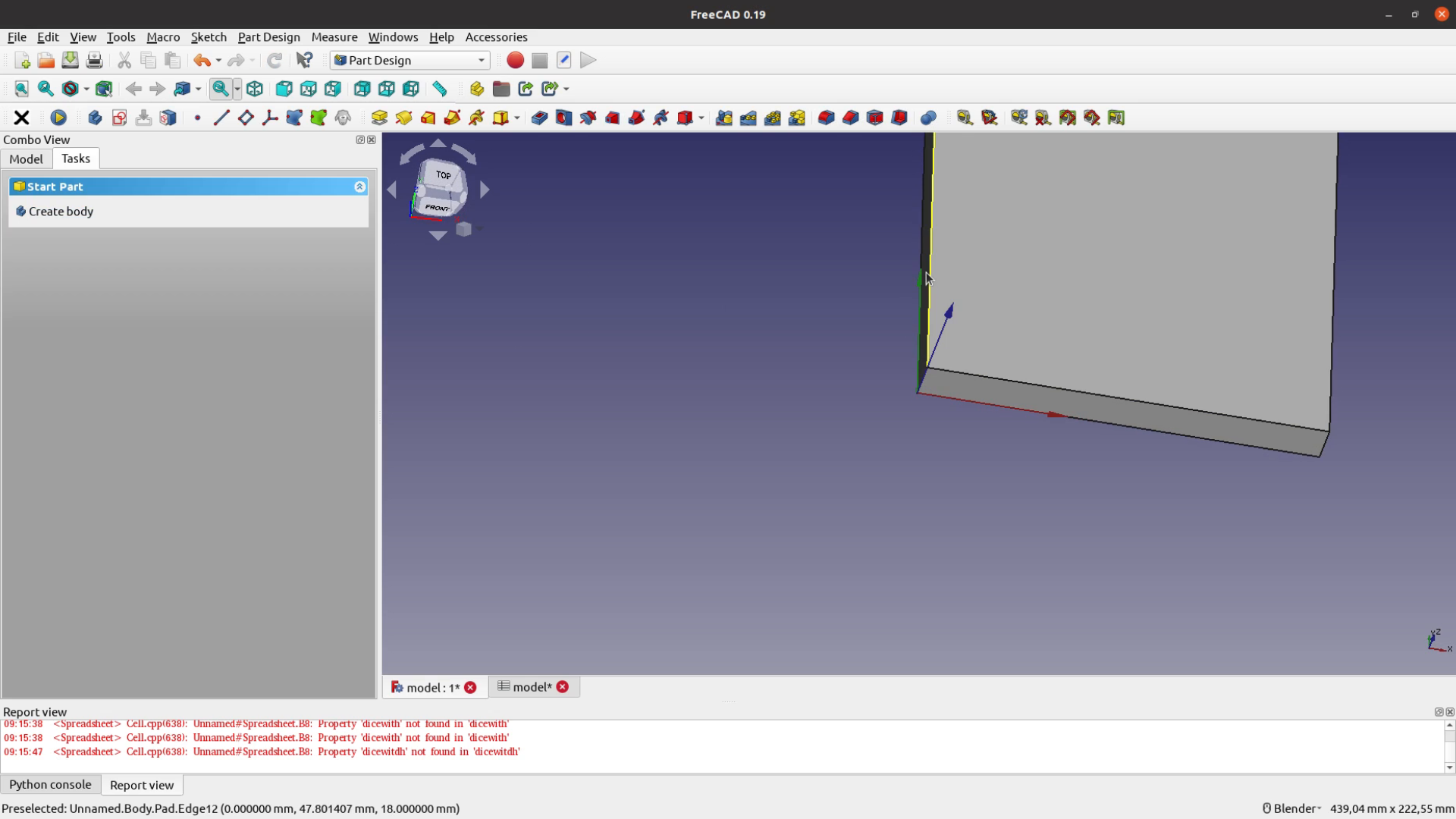
The size of the pad corresponds to materialthickness.
Each of the four corners gets a 5mm fillet according to the radius variable.
For the recess we create a new sketch in the XY plane. The size is dimensioned according to the dicewidth variable and the first recess is placed frameseparator away from the corner.

The depth of the pocket is as deep as the recess variable.

We then apply a MultiTransform with two LinearPatterns. The length of the array is the arraywidth variable minus the width of a single dice. Same goes for the other direction.
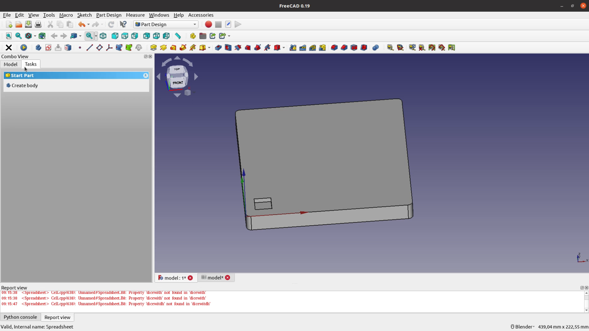
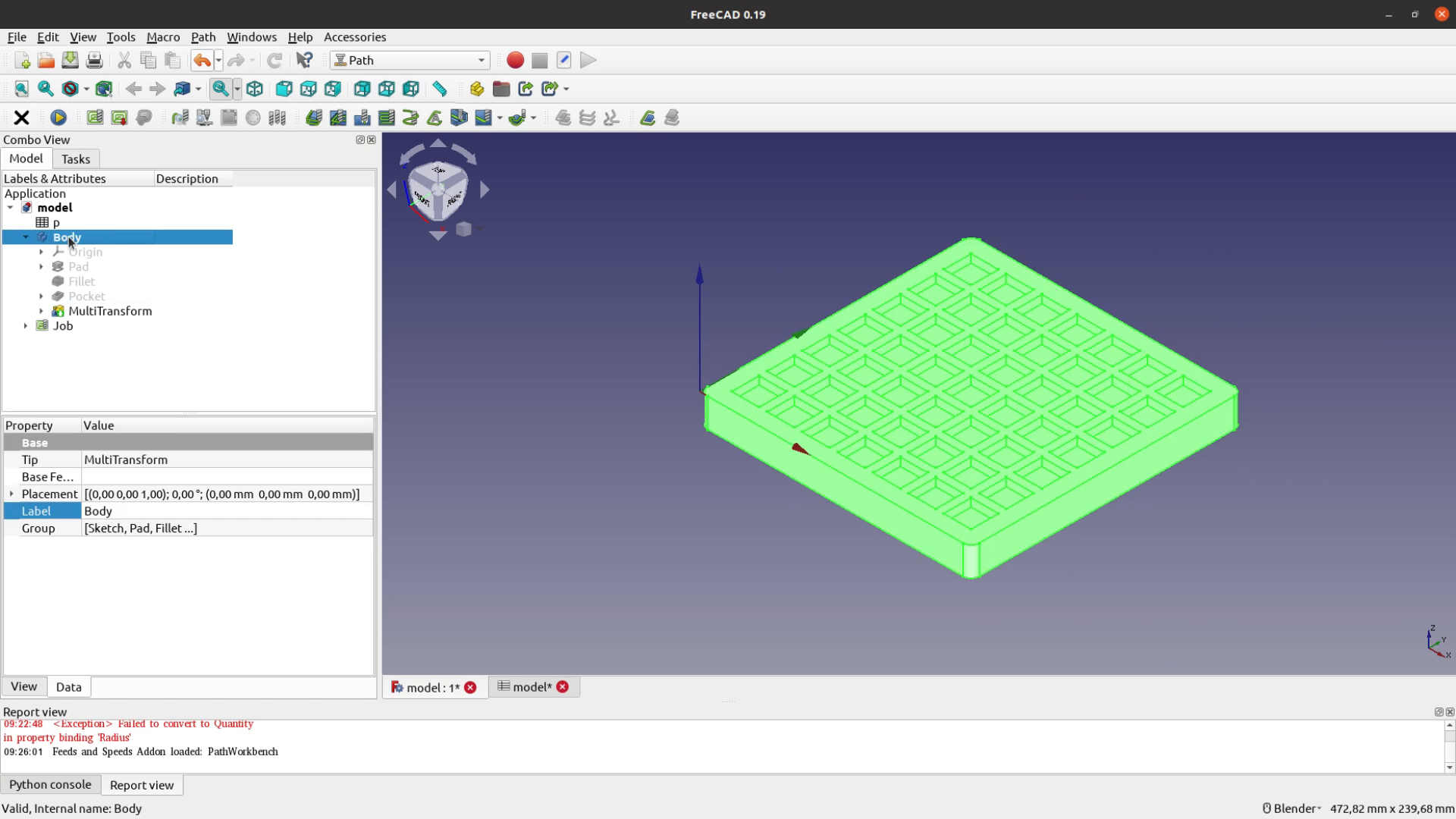
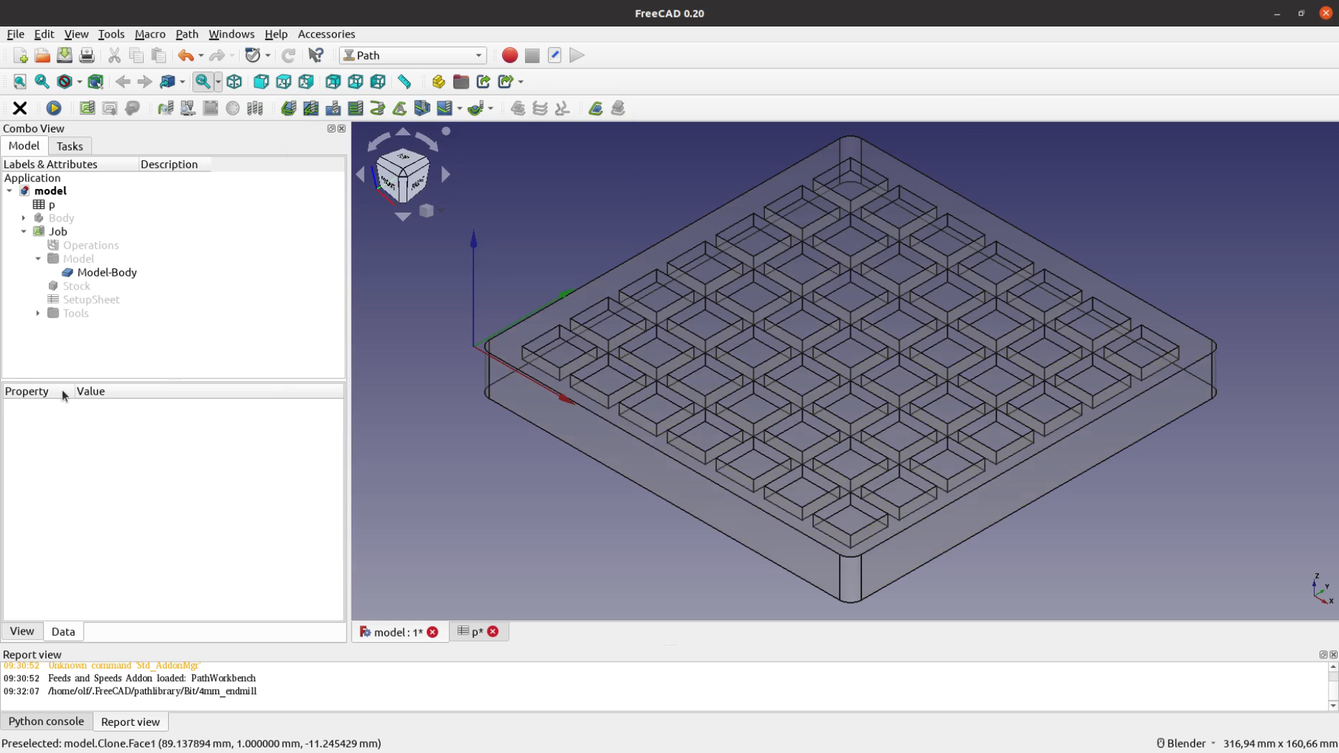
With these steps we are done with the CAD part. Before moving on to the CAM part let’s check if the model also works with other parameters. Looks good – we could create dice games as large as we want.

FreeCAD CAM with the Path workbench
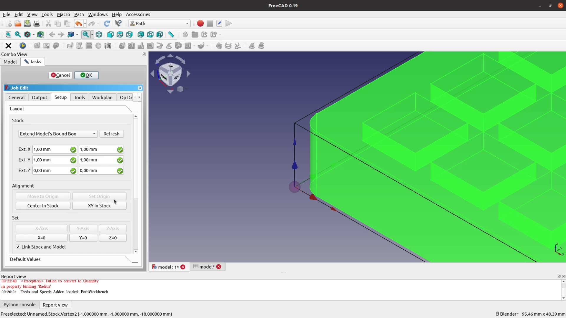
Now comes the CAM part and for that we switch over to the Path workbench. Here we create a new Job. In the new job task pane you can set the origin to any point of your model or your stock. My stock extends the model by 1 mm in X and Y direction on each side – which doesn’t matter that much as I will anyhow cut the piece free at the end. In the output tab you have to select the post processor that fits your machine. For common solutions such as GRBL or LinuxCNC there are post processors available. I had to write my own for the board I am using – which was also not a big deal.
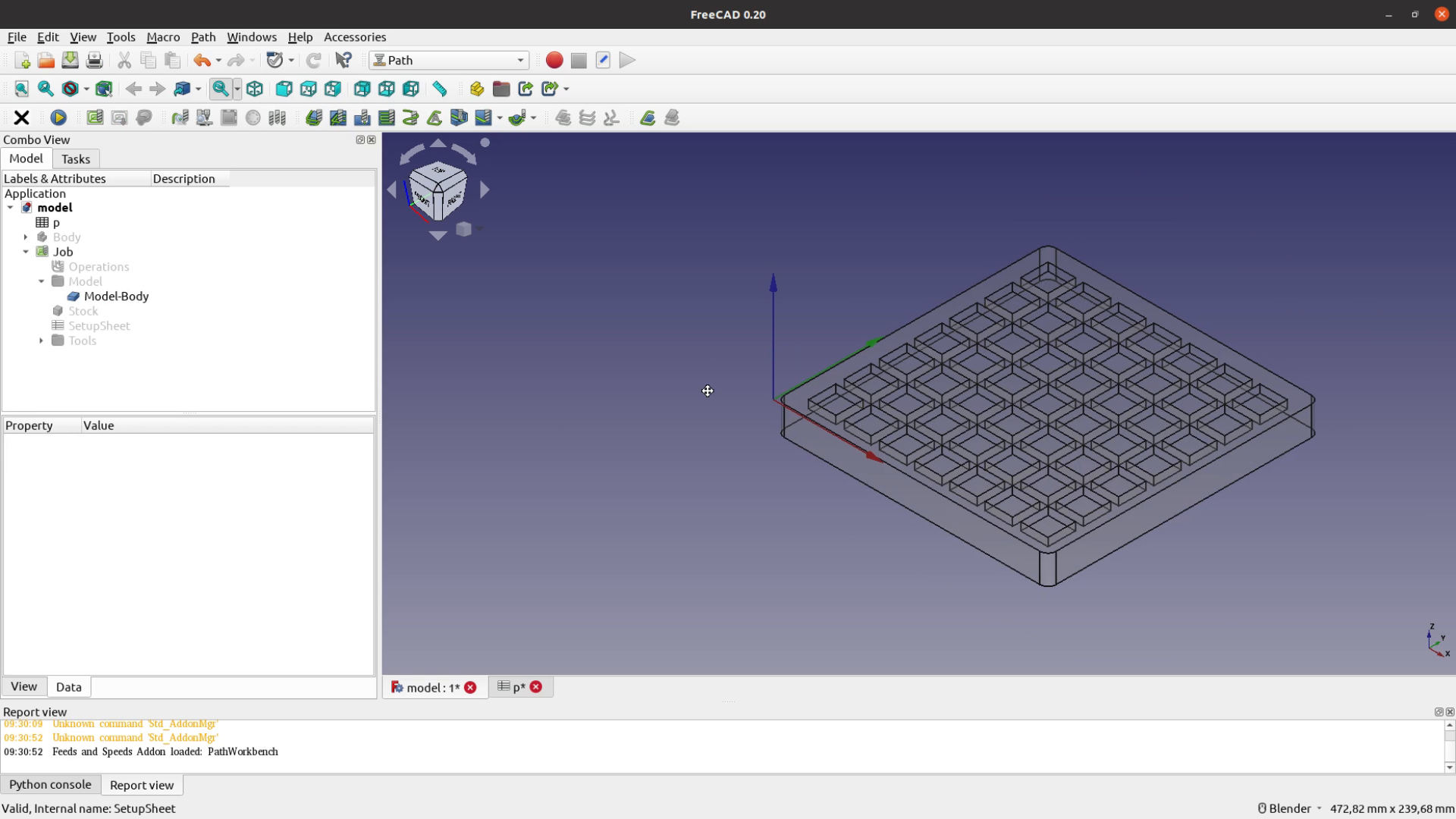
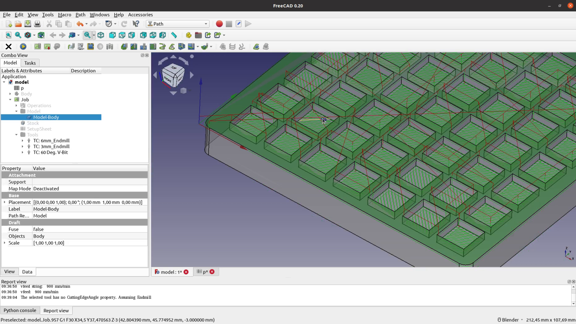
You can now hide the original model and work with the copy of the model that the path workbench created inside of the job.
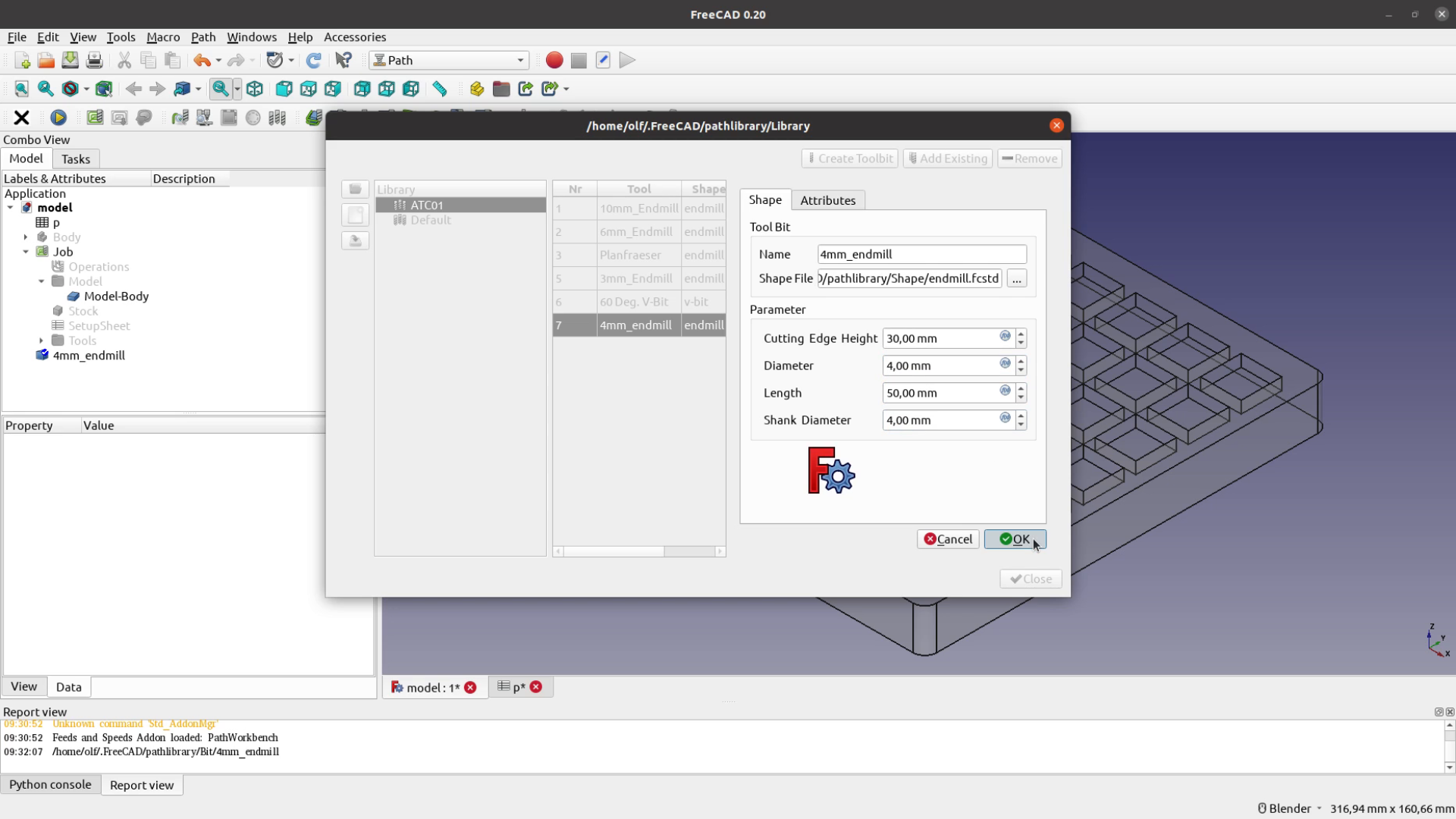
After creating the job the next thing is to create a tool. I have all the tools that I need for this job already in my library but let’s quickly create an endmill to show you the process. I select the shape of a tool on which the new tool will be based, and then choose a name for the new toolbit. Lastly I change the parameters of the tool like diameter and length.
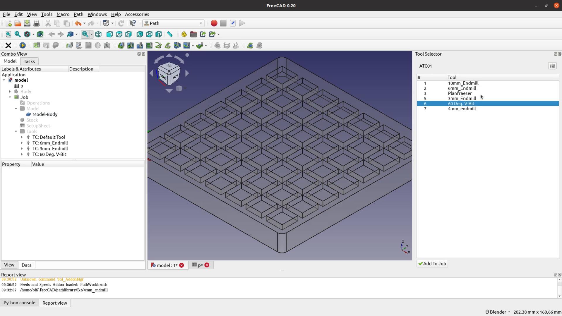
We can then add tools from the tool dock to our job.
FreeCAD CAM: Path Feeds and Speeds Addon
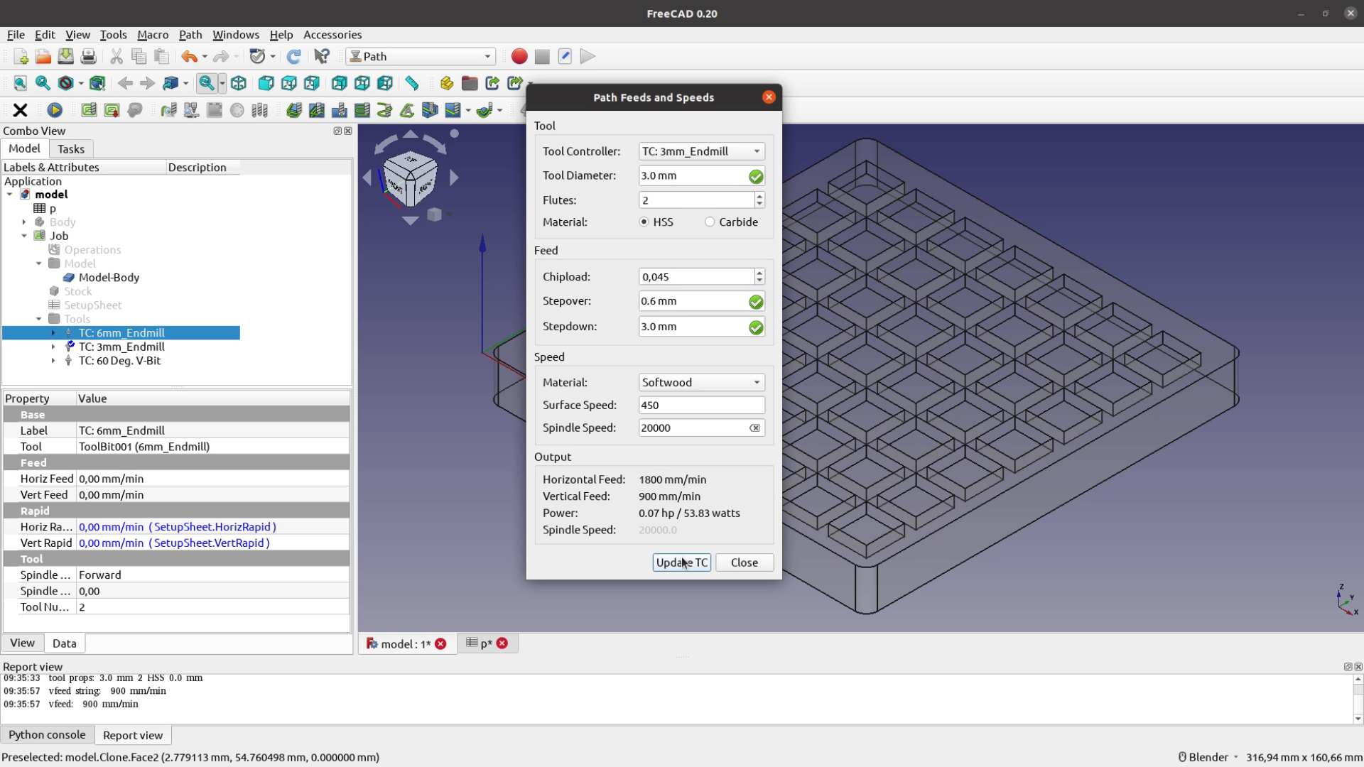
The Path Feeds and Speeds Addon is a very handy tool that you can download from GitHub. It has a small bug when you locale has a comma as the decimal separator. In order to get the right values just select another tool before going back to the original one you want to work with.
The chipload and the surface speed that you can get from your tool manufacturer or generic reference tables. This overview from Sorotec is a good starting point (in German). The addon produces a good starting point for the feed and speed of your job and we can directly update the toolbit parameters.
After setting the speed and feed for the tool when cutting we also have to change the feed rate for the moves in between cuts.
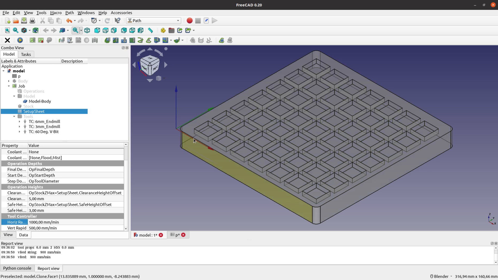
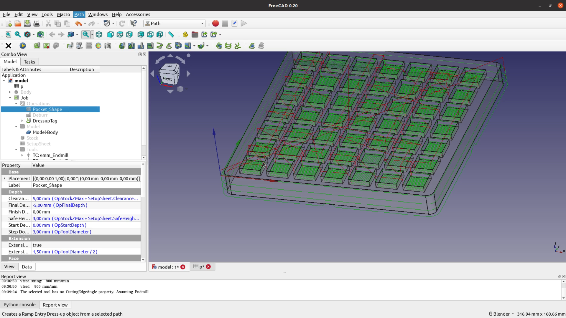
The first operation we want to create are the pockets for the dice. Selecting multiple areas or edges can sometimes be a bit cumbersome – I therefore wrote a small macro that helps to select all faces that have the same size. You can download this macro here.
For the pocket operation we select a ZigZagOffset pattern that will clean up the bottom and then also follow the profile. A 50% stepover will help to create a cleaner finish.
We then add a Deburr operation to all the edges at the top to give them a small chamfer. I first selected the wrong tool and used an endmill instead of a V-Bit. We will come back to this later.

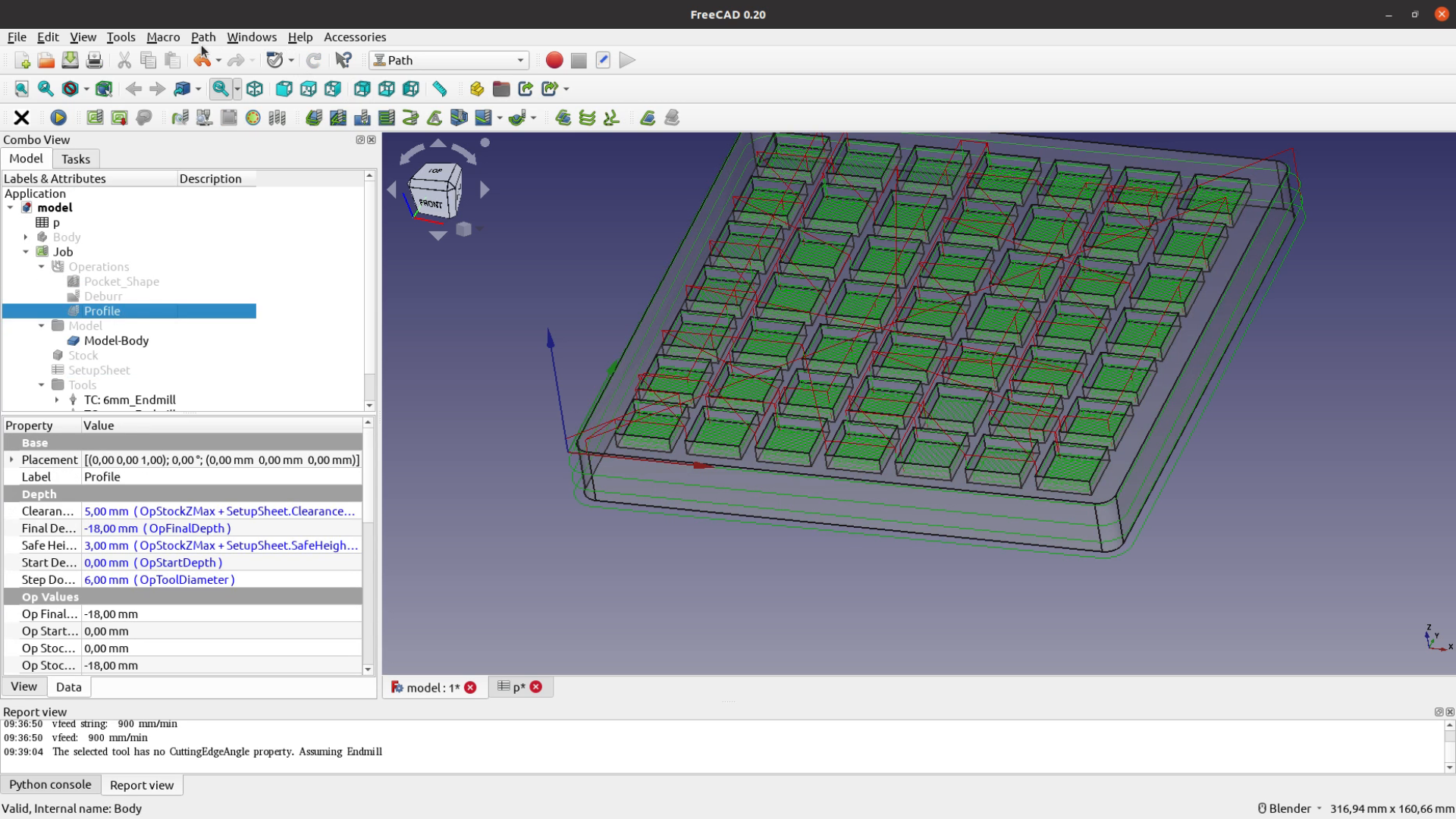
The third and last operation is to select the bottom of the model and run a profile operation to cut the piece free.
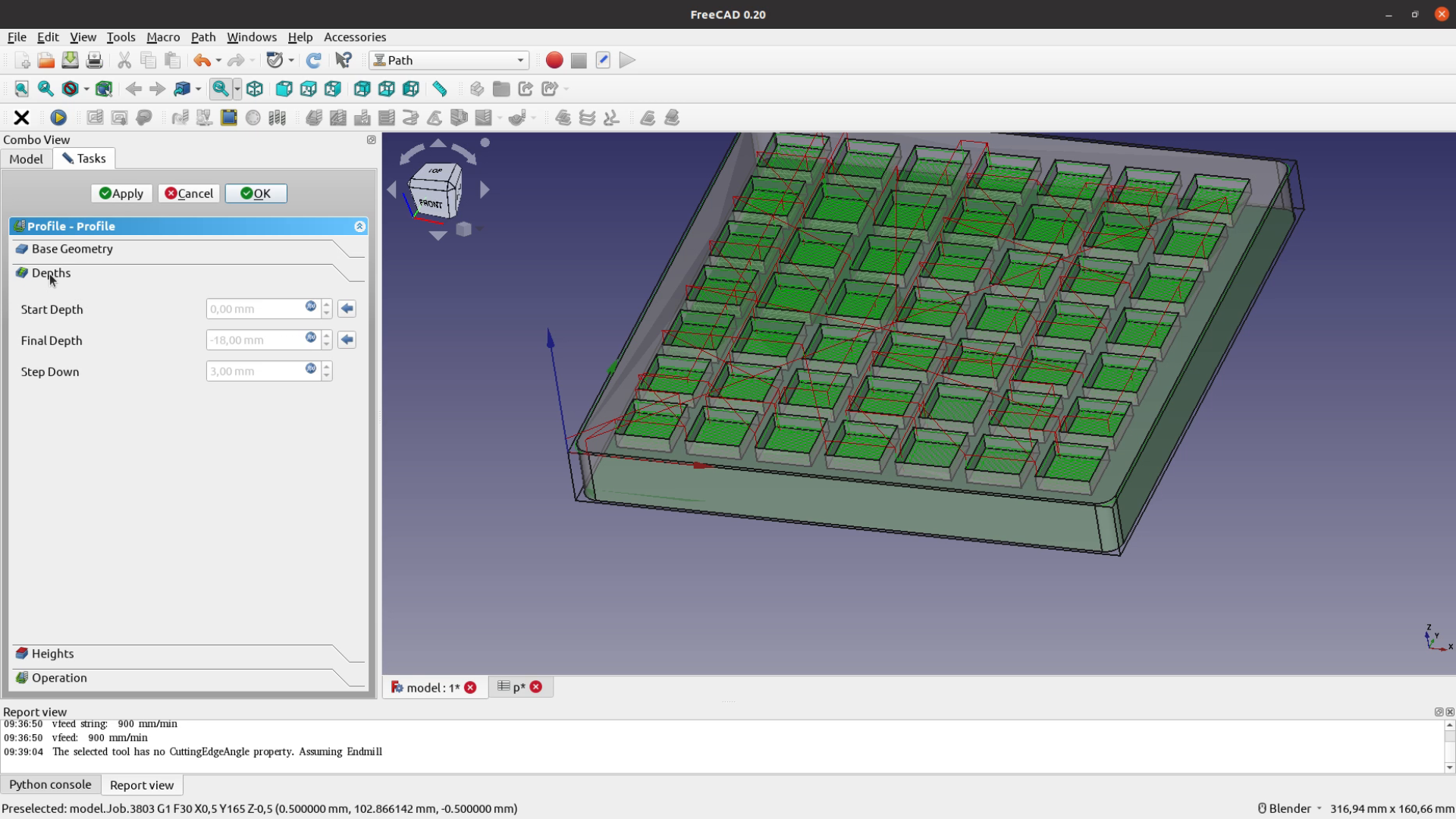
As we want to avoid that the piece flies through the room once it’s cut free we add tabs to hold it in place. In FreeCAD this is done with a Dressup to a path – in our case a Tag Dressup.
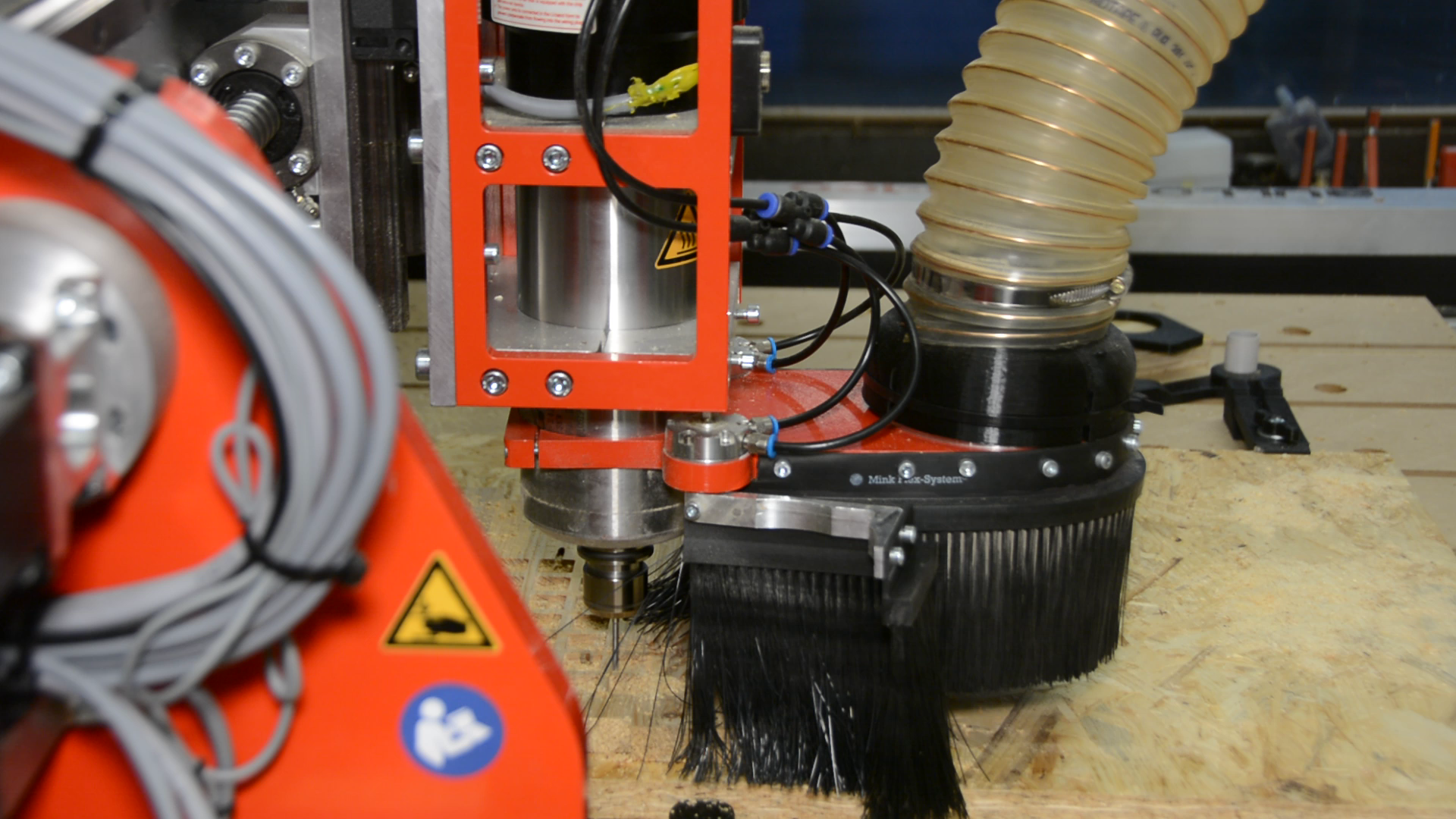
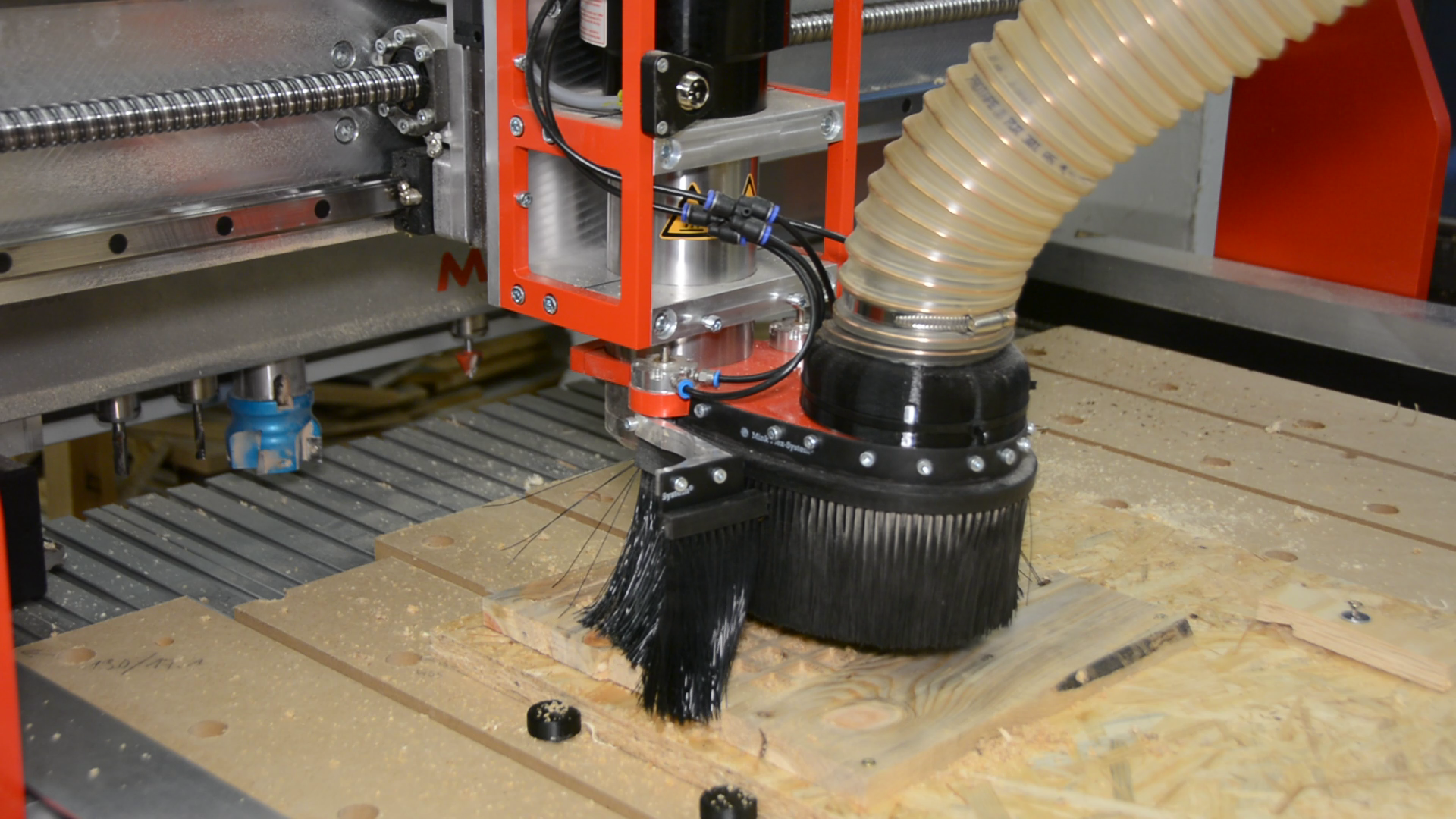
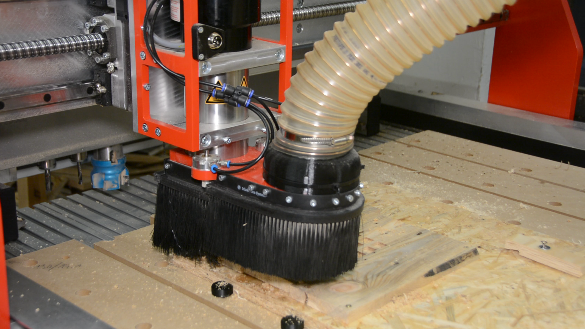
CNC – into the real world
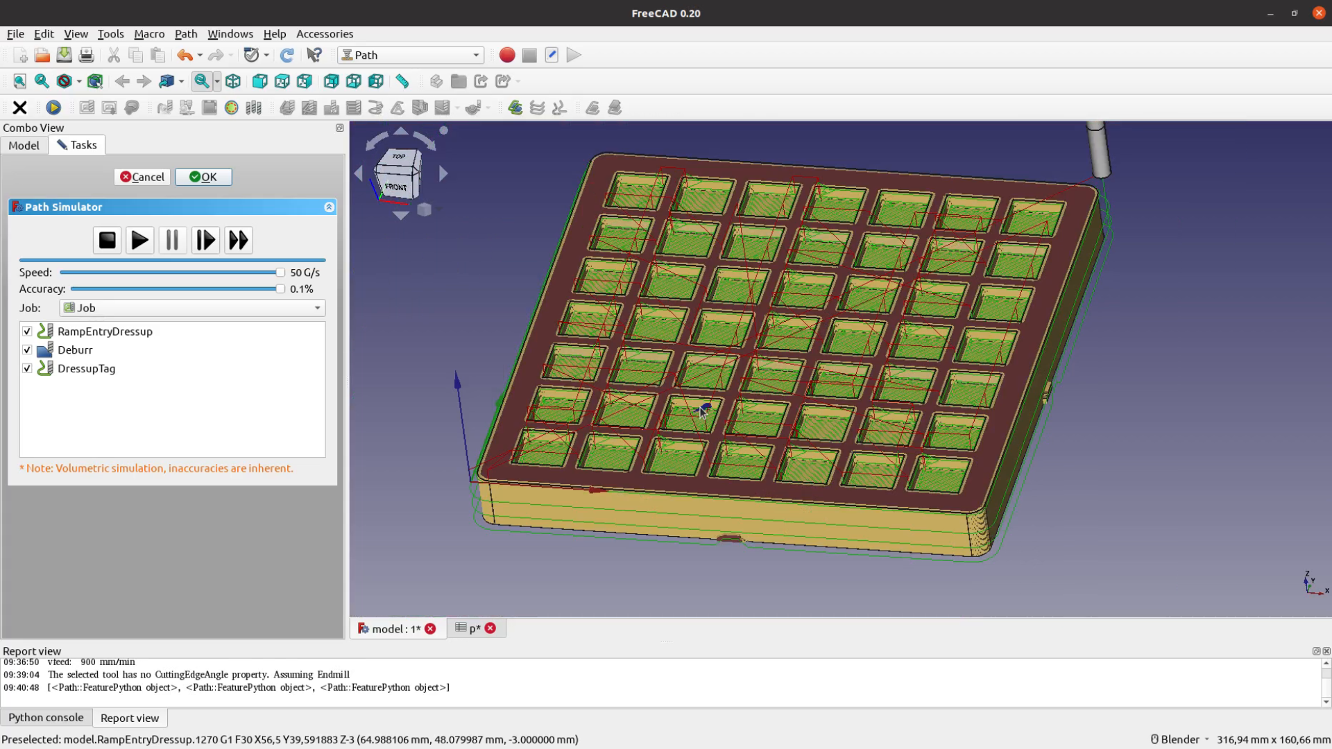
When running the simulation I could have spotted the fact that the profile is being cut by a 3 mm endmill and not a 60° V-Bit. After exporting the code and cutting all the pockets
I quickly realized that the V-Bit was not changed. So I went back to FreeCAD and replaced the 3mm endmill with a V-Bit and continued the job without the first operation.
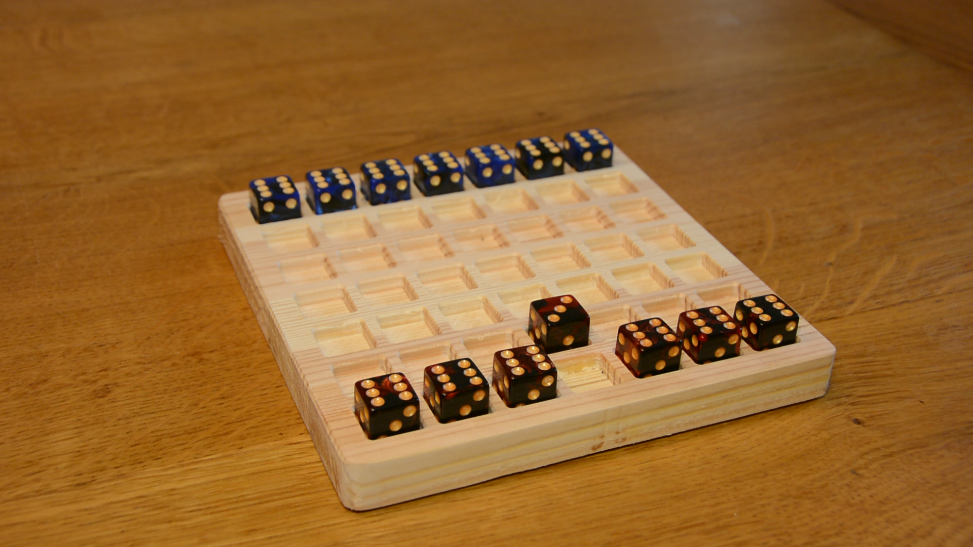
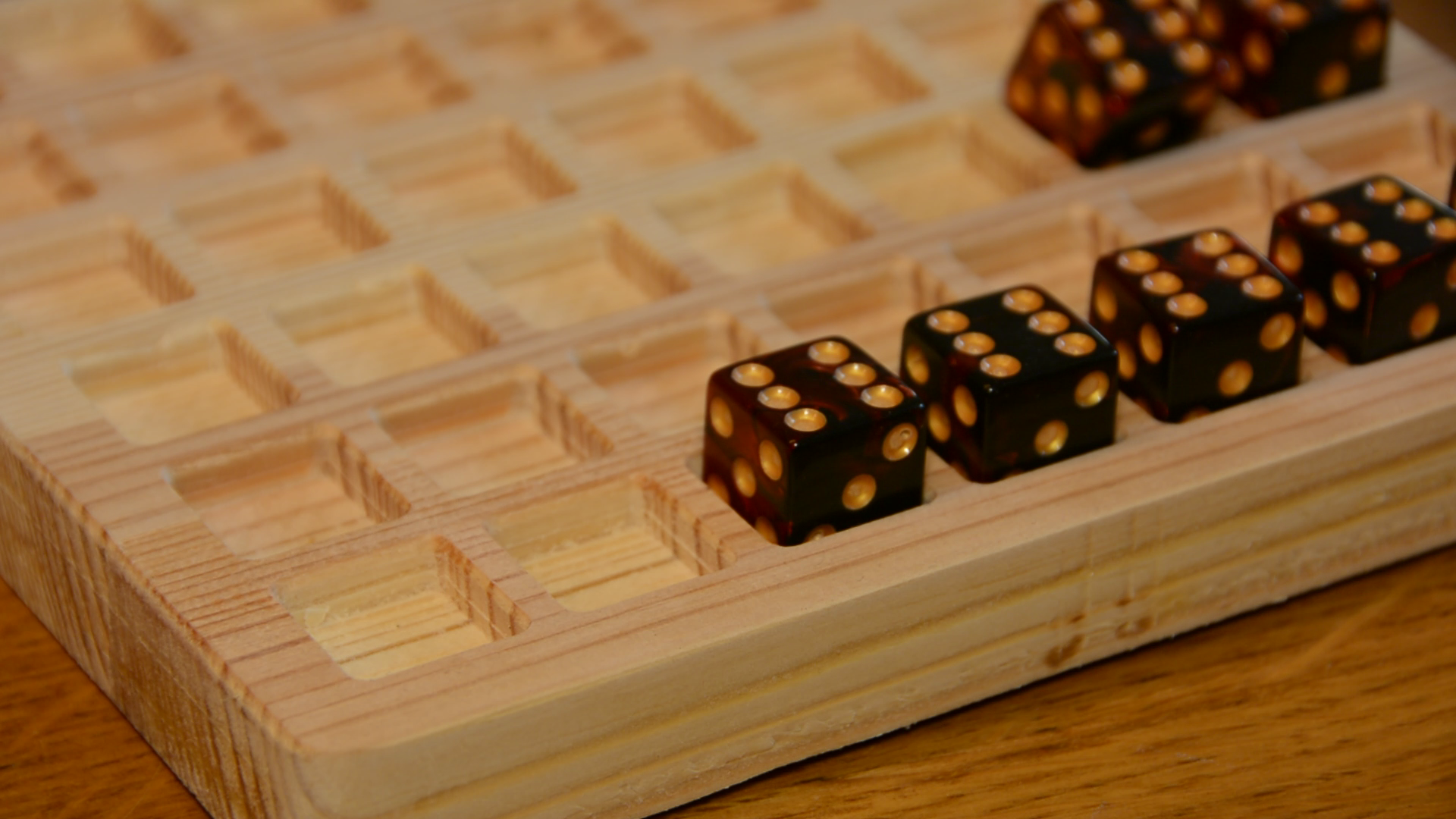
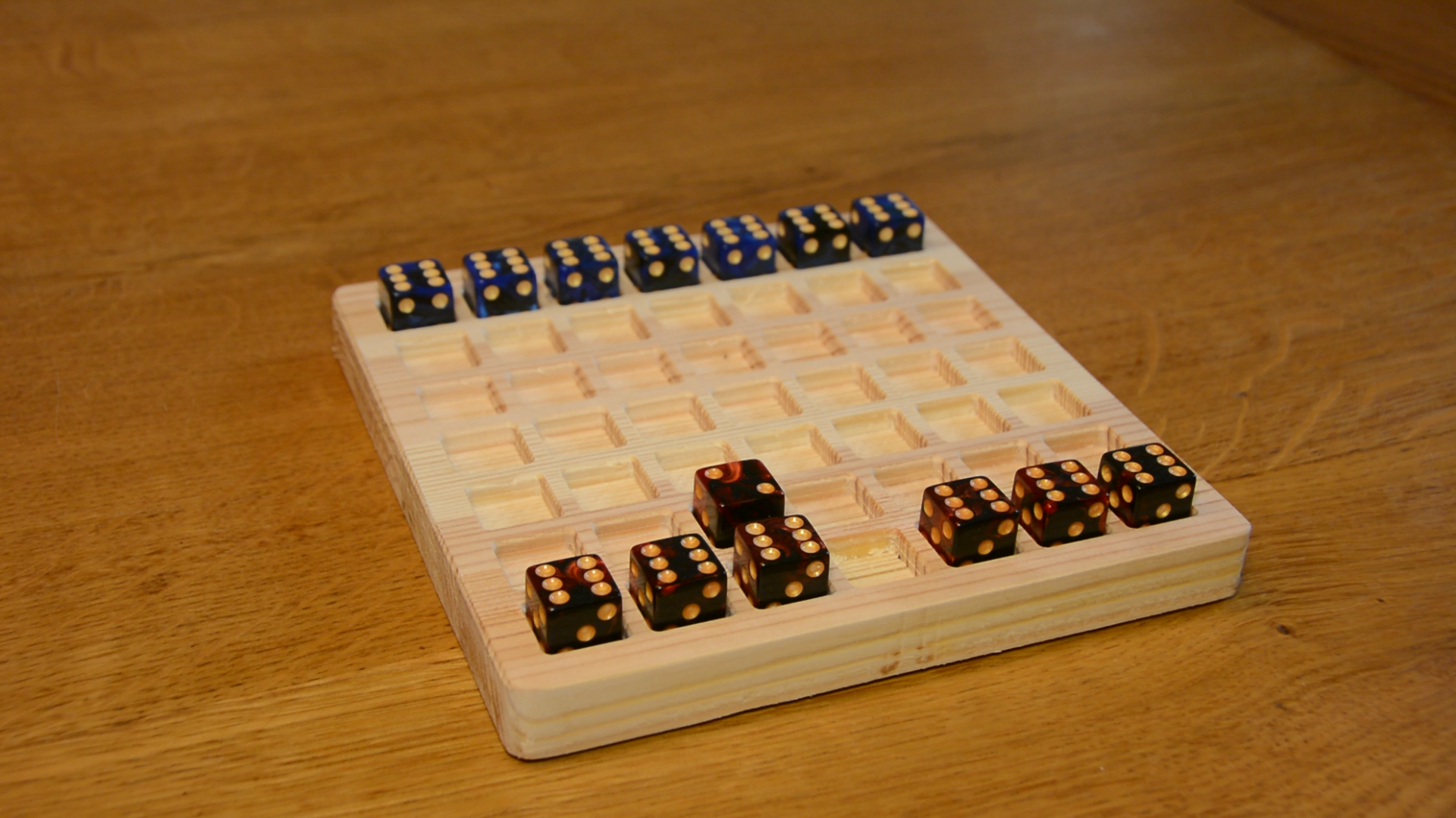
The dice game
The game turned out really nice and in case you are curious let me quickly explain the simple rules:
All dice start in the first row, the number 6 facing up and the number 3 facing towards the player.
You can move the dice forward by rolling it over – in this case it changes it’s number.
You can also roll the dice sideways but not backwards.
If there is one or if there are multiple dice of your own or from your opponent in front of your dice you can jump across these – without changing the number of the dice. You can chain multiple jumps together.
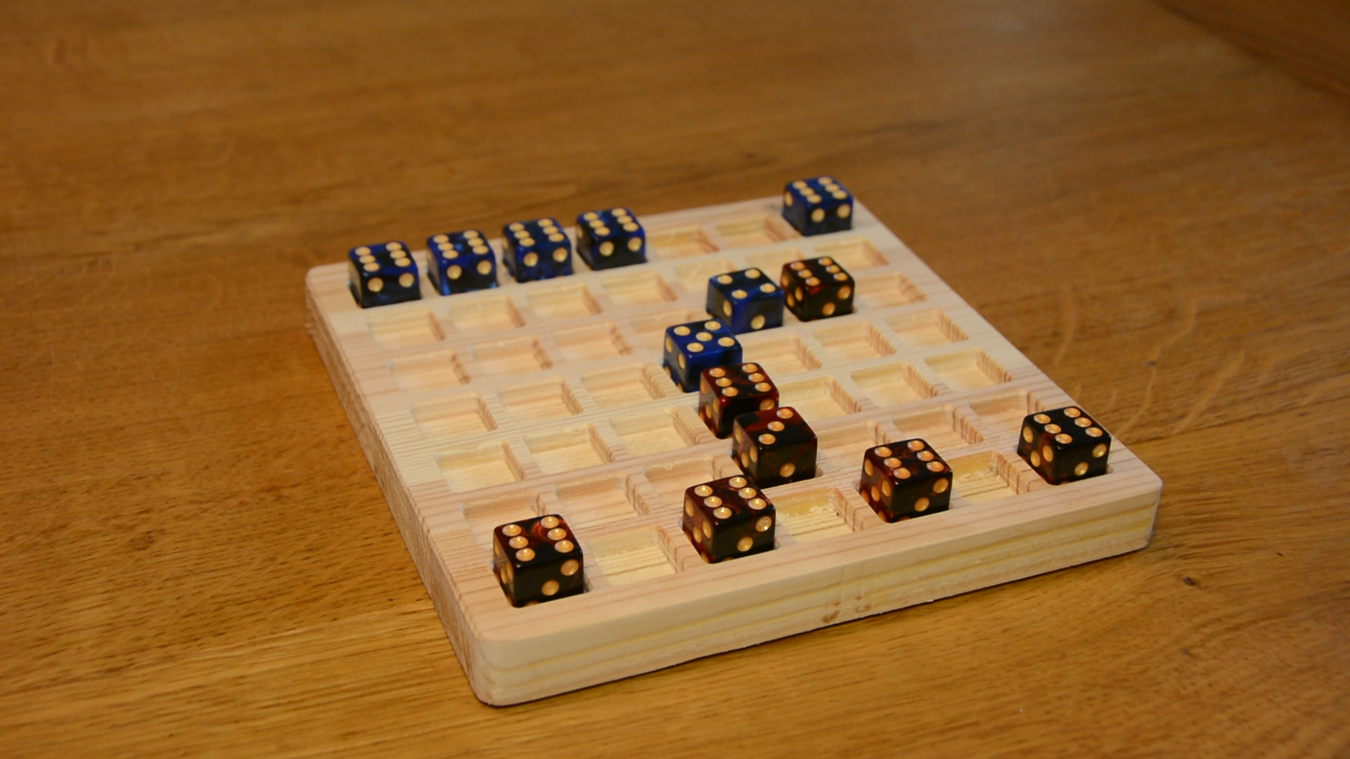
The game ends as soon as one player has all dice in the opposite row. The winner is the player with a higher number of spots on the dies in the last row.

Hi, which CNC machine are you using?
I am using the Bulldog 150-100. There will be a dedicated video and article on the machine soon.
Hi, Nice Content! I´m having some troubles by installing the SmartSelect Macro. The Report look like this:
09:01:55 Traceback (most recent call last):
File “C:/Users/htsx0/AppData/Roaming/FreeCAD/Macro/SmartSelect.FCMacro”, line 79, in
panel = SelectTaskPanel()
File “C:/Users/htsx0/AppData/Roaming/FreeCAD/Macro/SmartSelect.FCMacro”, line 29, in __init__
self.form = FreeCADGui.PySideUic.loadUi(path_to_ui)
File “”, line 4, in
: Cannot open file
i need some help. Thanks
It looks like the link to the alias macro is dead. I´d like to see that one.
And, thank you for the video on making this dice game. I am using your instructions to create a daily meds tray.
Thanks again!