
In this article we will use 3d printed templates to route a very precise pocket with multiple depths – with no CNC.
The problem …
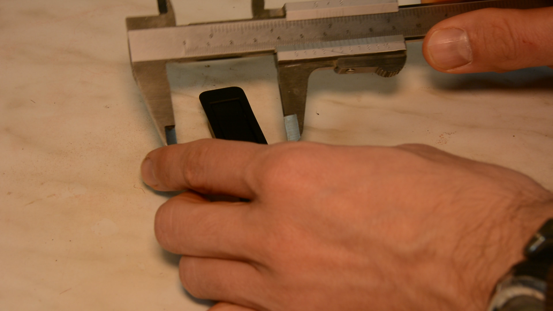
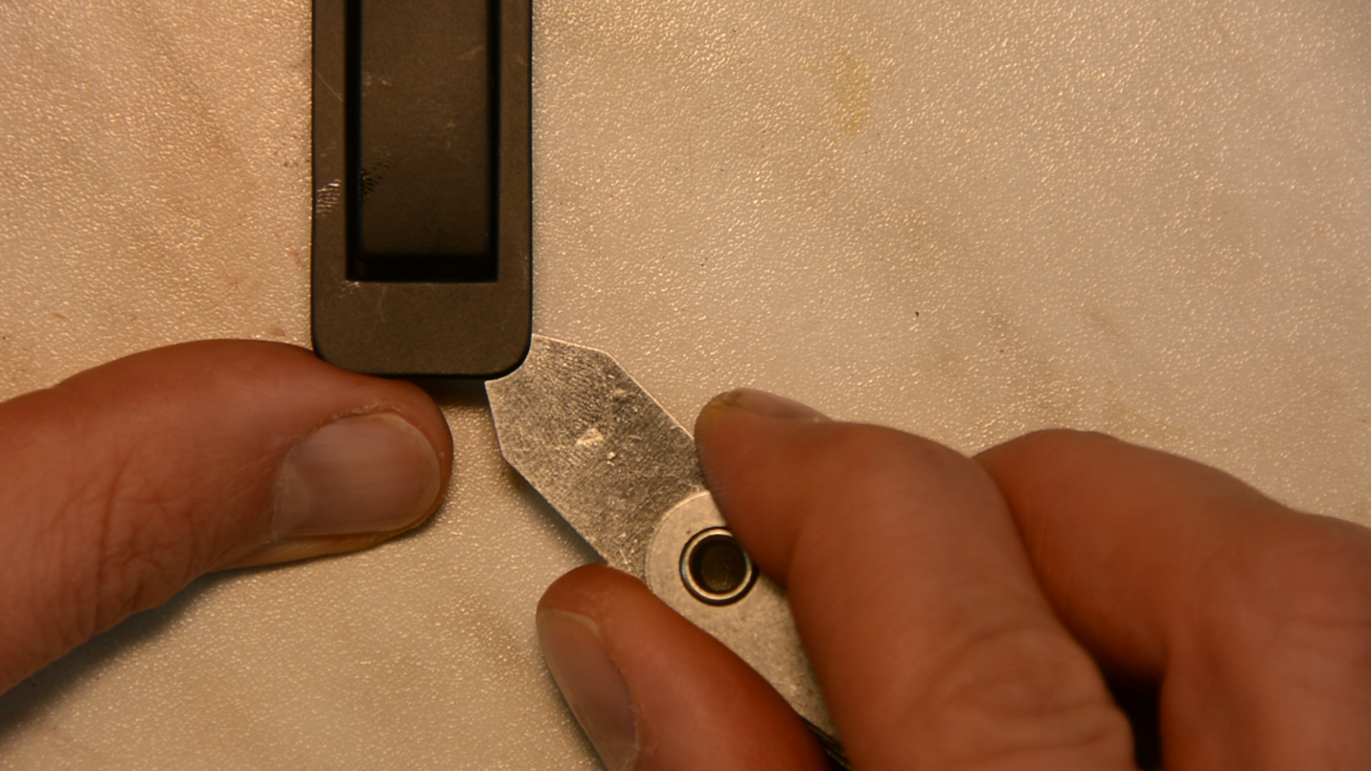
In our bathroom we have a hook that has seen already better days. I would like to replace this awful broken hook with a nice thick oak board that has several of these hooks.

These hooks are designed for installation with a router and a 16 mm bit.

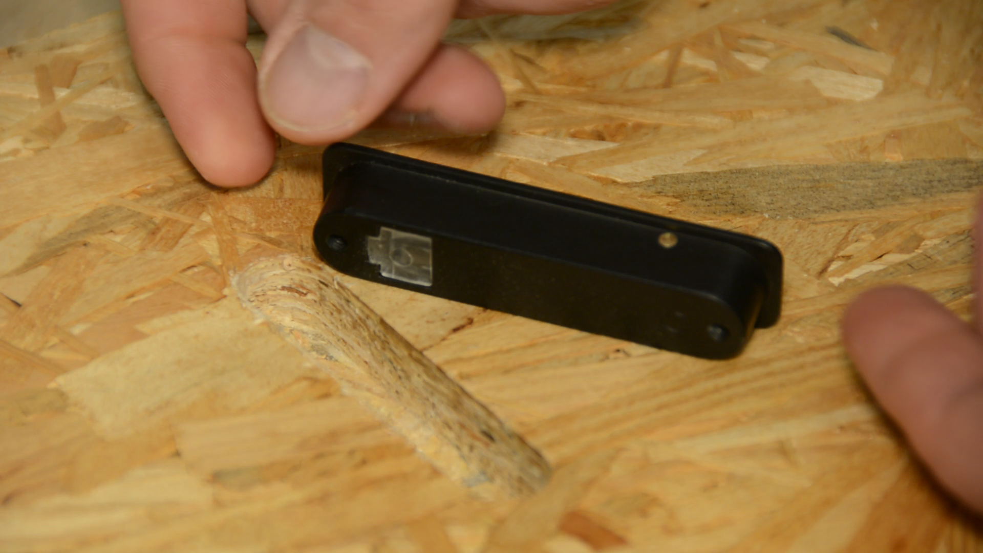
They sit in a 16 mm wide slot that is easy to route as the lip is covering up all the mistakes. However I don’t like the aesthetic of the lip sitting proud on the surface.
In this article I will show you a method how to use 3d routing templates to create this shape without a CNC.
Milling and cutting the lumber
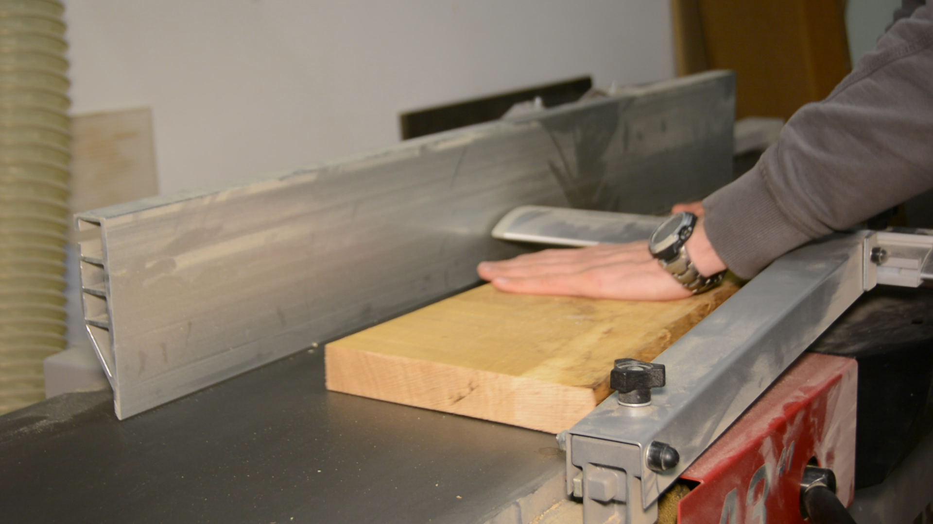
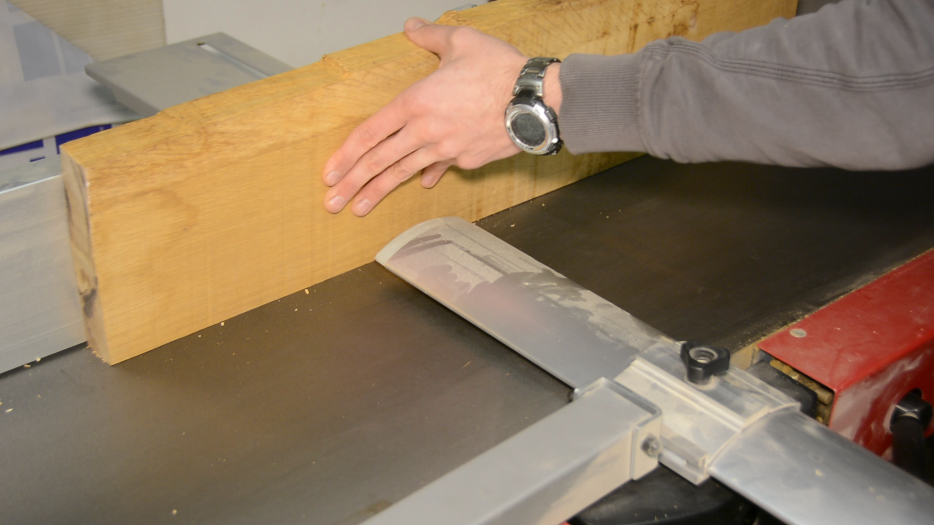
Before getting to the routing we have to prepare the board. I cut the board to the approximate length on the miter saw. On the jointer I create one flat side and one straight edge.

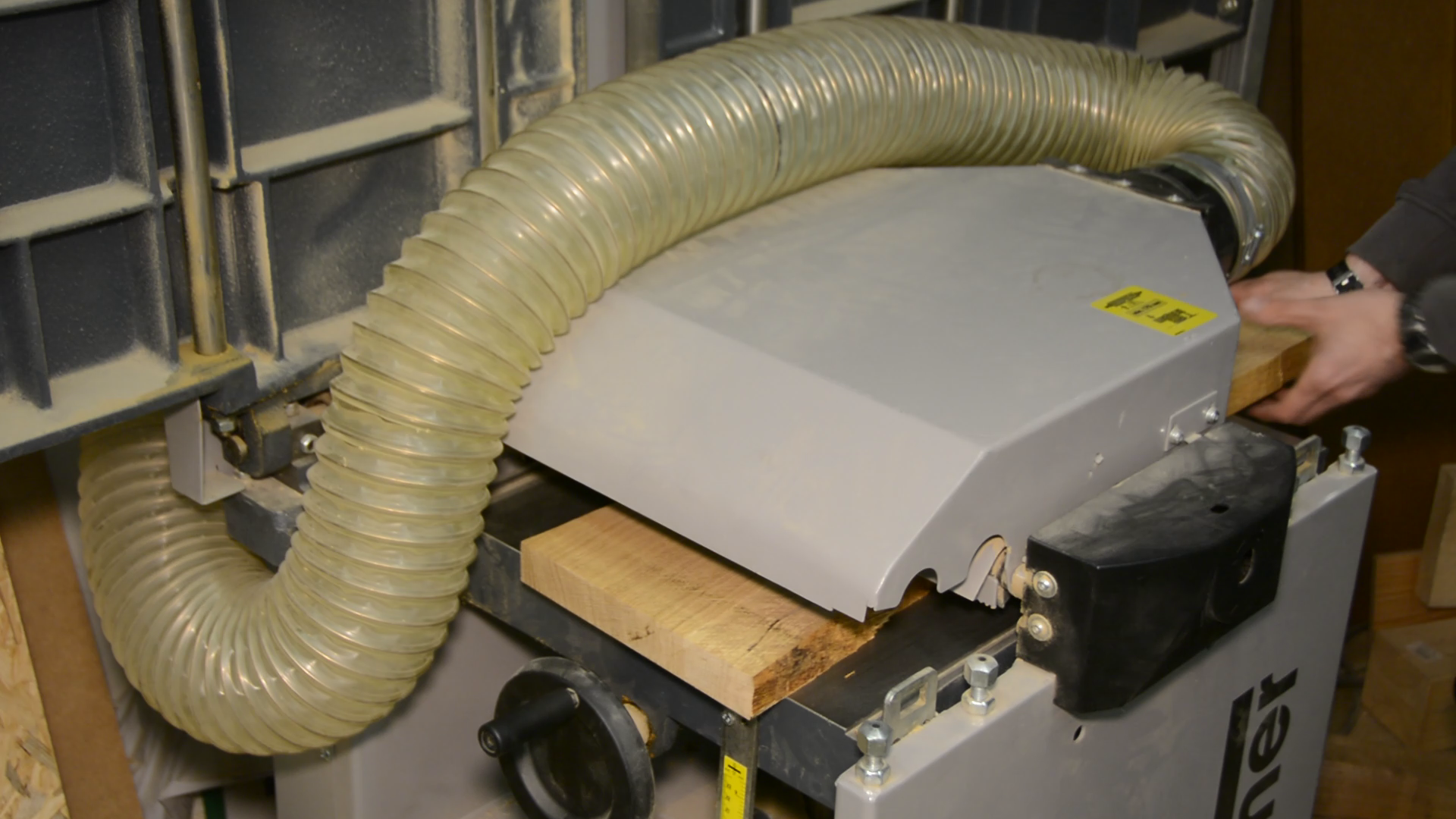
Next I run the board through the thickness planer to get two flat surfaces.
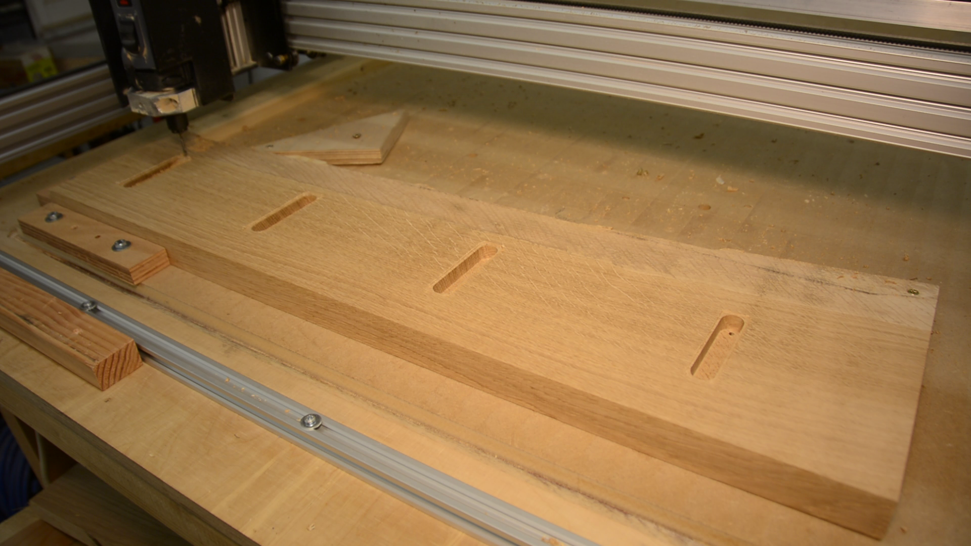
As I do have a CNC I throw the board on the bed and let the CNC do its job.
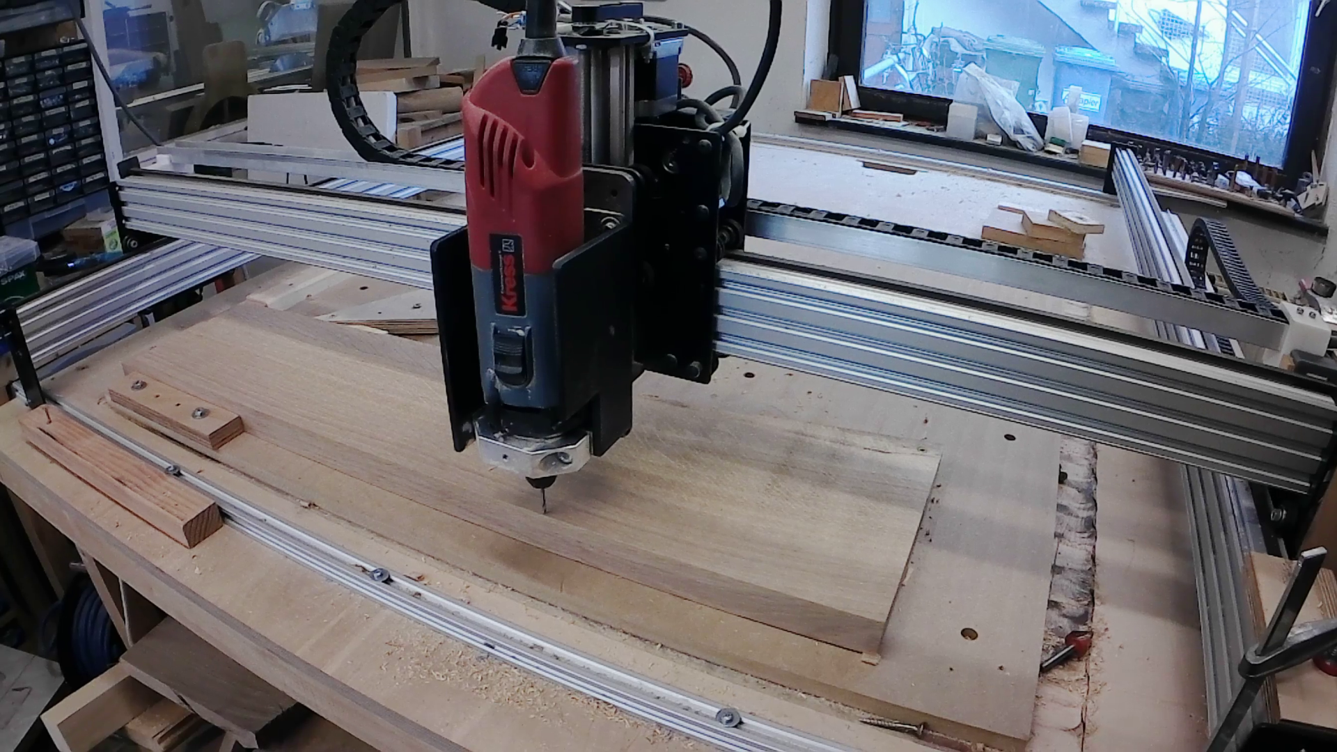
But while the CNC is working let’s look at an alternative method on how to get this job done with no CNC at hand – using 3d printed templates.
Designing 3d printed templates for routing the shape
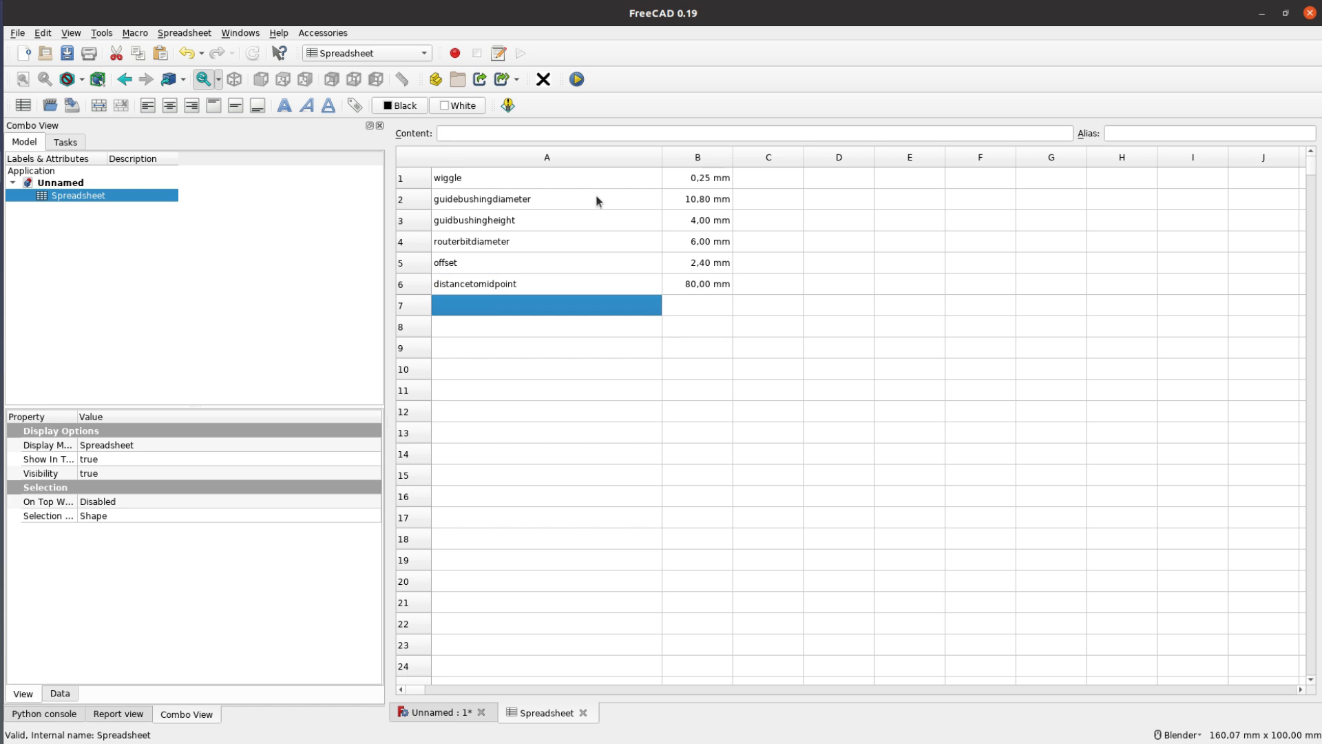
It all starts in the office with taking measurements and developing a CAD model in FreeCAD. The file can be found at the end of the article in the resource section.
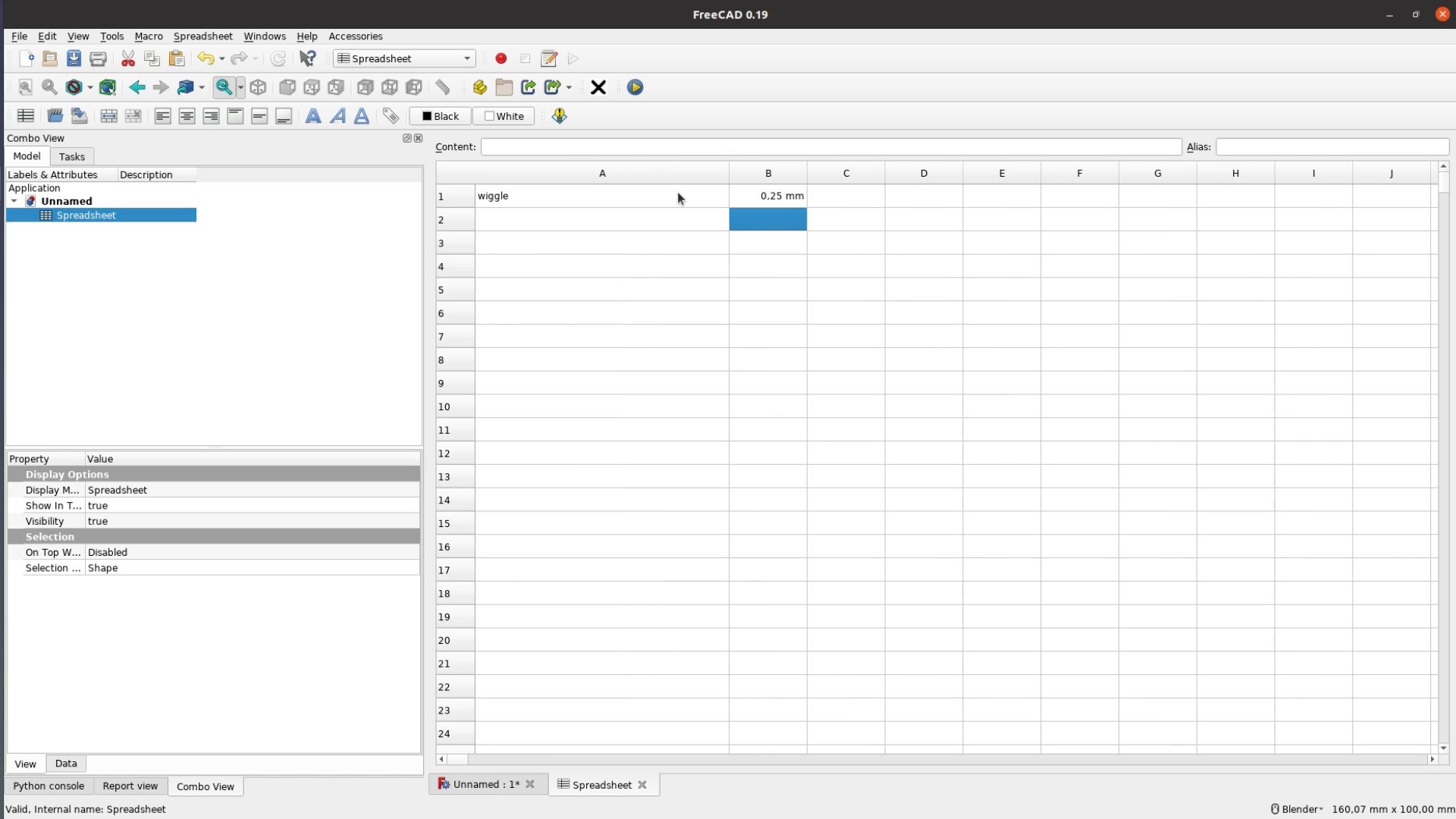
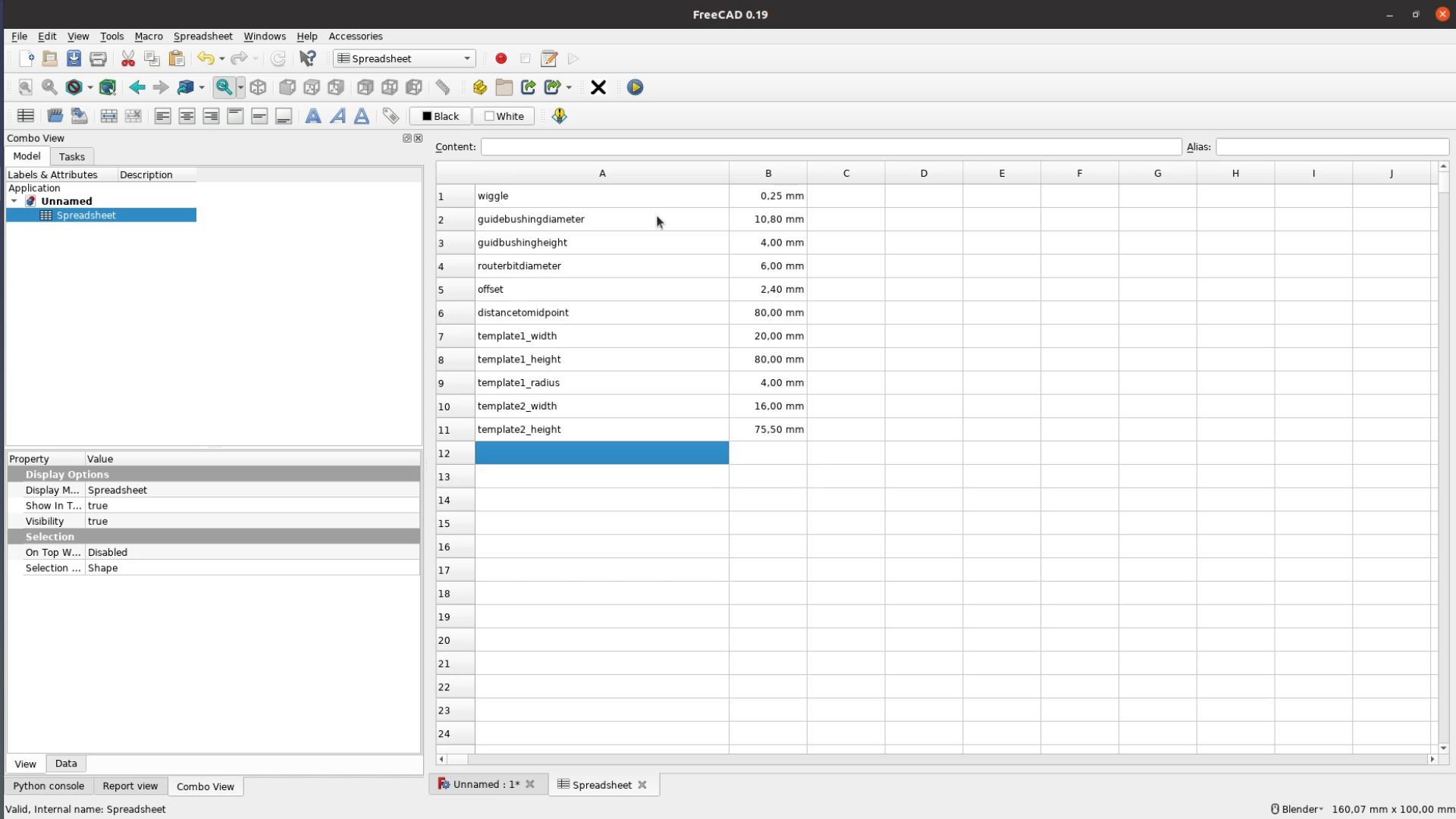
In FreeCAD we create a spreadsheet that contains all the relevant parameters. The first one might be the most important one. It is the wiggle room that we need in order to fit two pieces together. In my experience having half a millimeter to play with – so 0.25 mm on either side works quite well.
Next we have to type in the dimensions of the guide bushing and the routerbit we are using so that we can calculate the offset. The distance to the mid point is how far away we want to position the hook from the edge of the board.
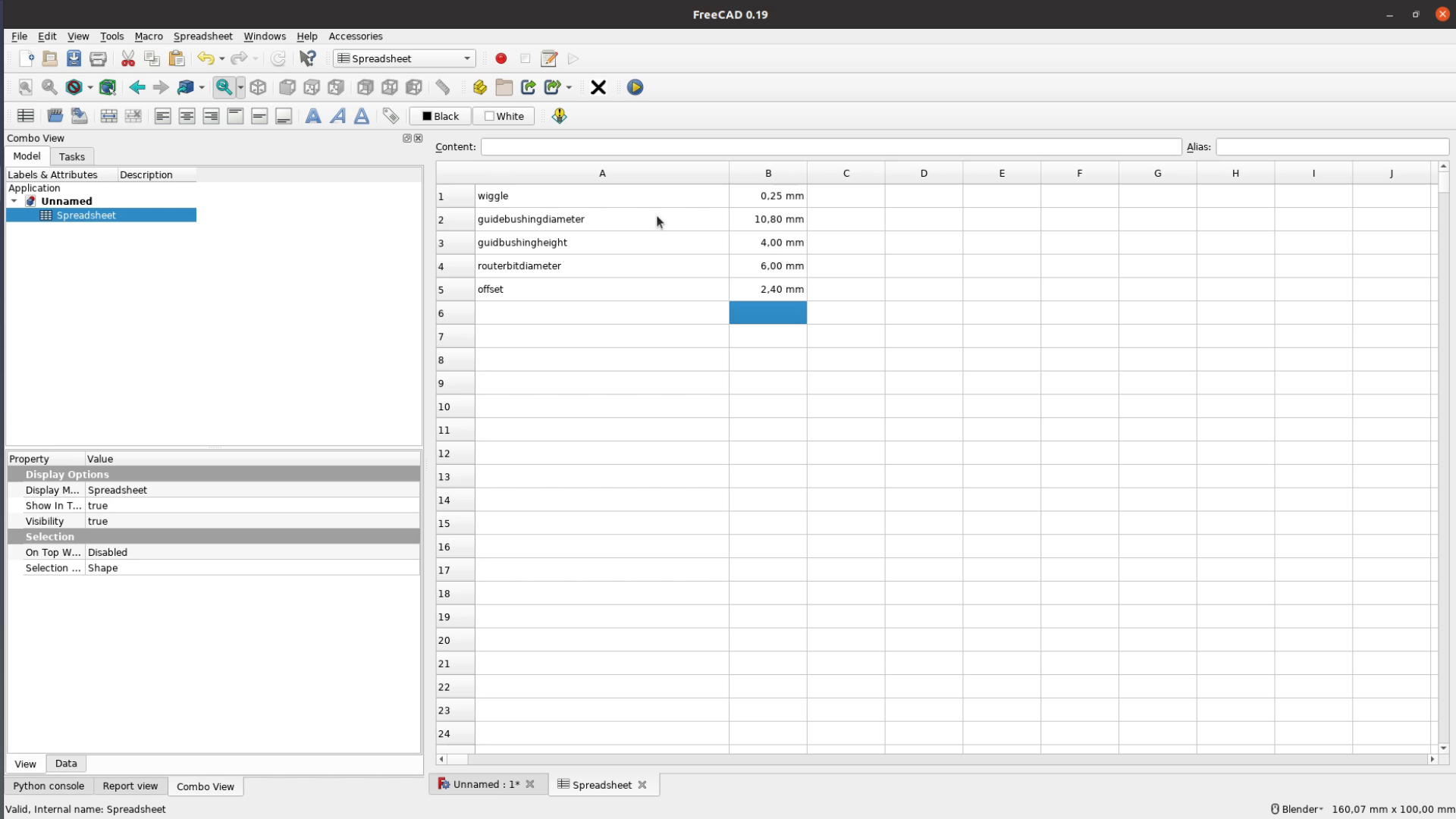
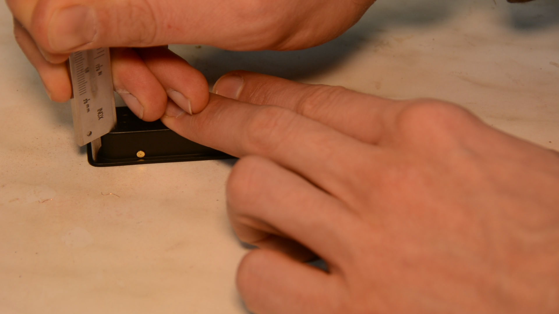
For the first template we need to measure the height and the width as well as the radius of the corners. Having a radius gauge is super handy for these kind of tasks.
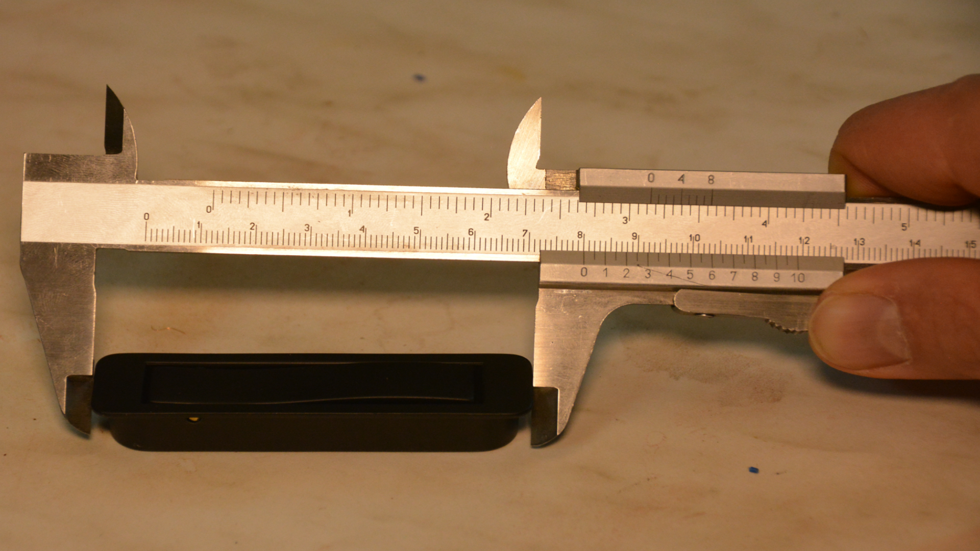
Template 2 is much simpler as it only has a width and a height.

For the third template we only need the distance of the two screw holes.

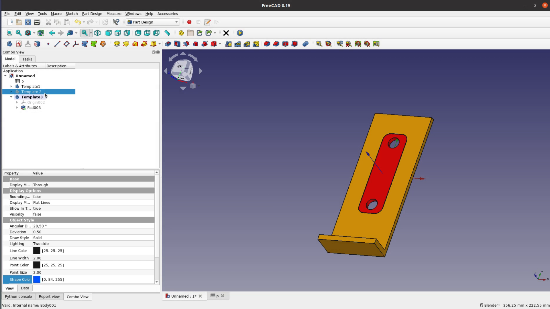
Modeling
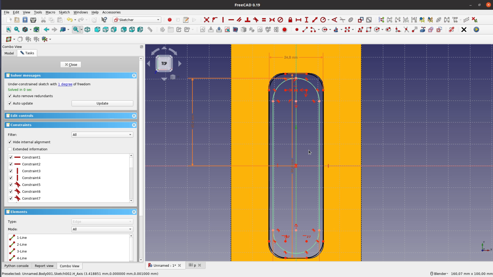
Modeling the actual shapes in FreeCAD is quite simple. The first template is square with fillets with the size increased by two times offset and our wiggle room.
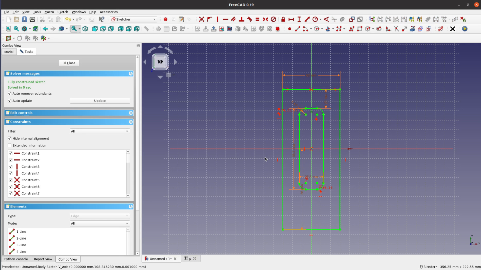
This shape then become a cutout in a larger template. After finishing the sketch we pad up the surface and add a small lip to register the jig against the board.
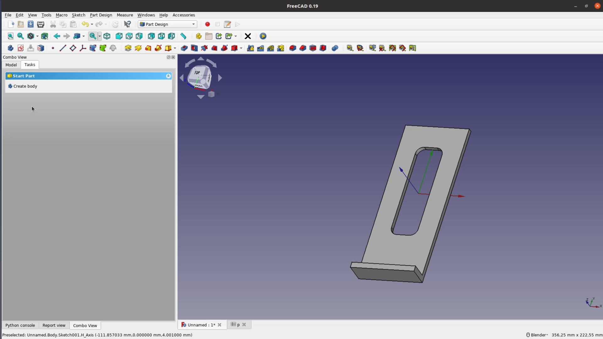
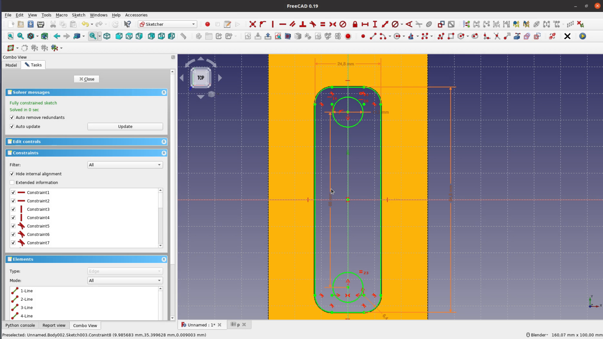
The second template should later on sit in the first one. So we first create the actual template form which consists of two half circles and two lines that are spaced by the dimensions from the spreadsheet – again adding the offset and the wiggle room. As an outer form we produce the exact same shape as for the first template – a little bit undersized.

After padding up the second template the last one is pretty much identical regarding the outer form just that we add this time two holes that have the diameter of our guidebushing plus the usual wiggle distance.

I send these forms to the 3d printer withthe simple Macro I described in detail in one of my last videos. If you don’t have a 3d printer you could create a drawing and cut it out on the scroll saw. I did this a lot before the area of 3d printing and laser cutting.

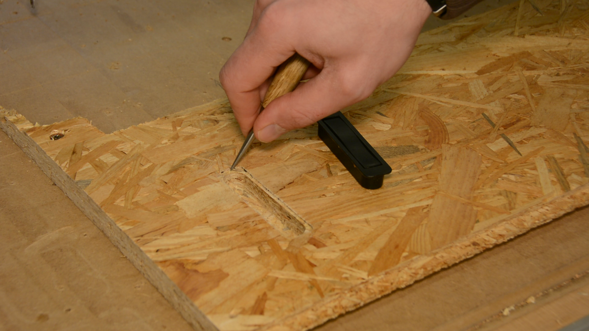
Testing the 3d printed templates
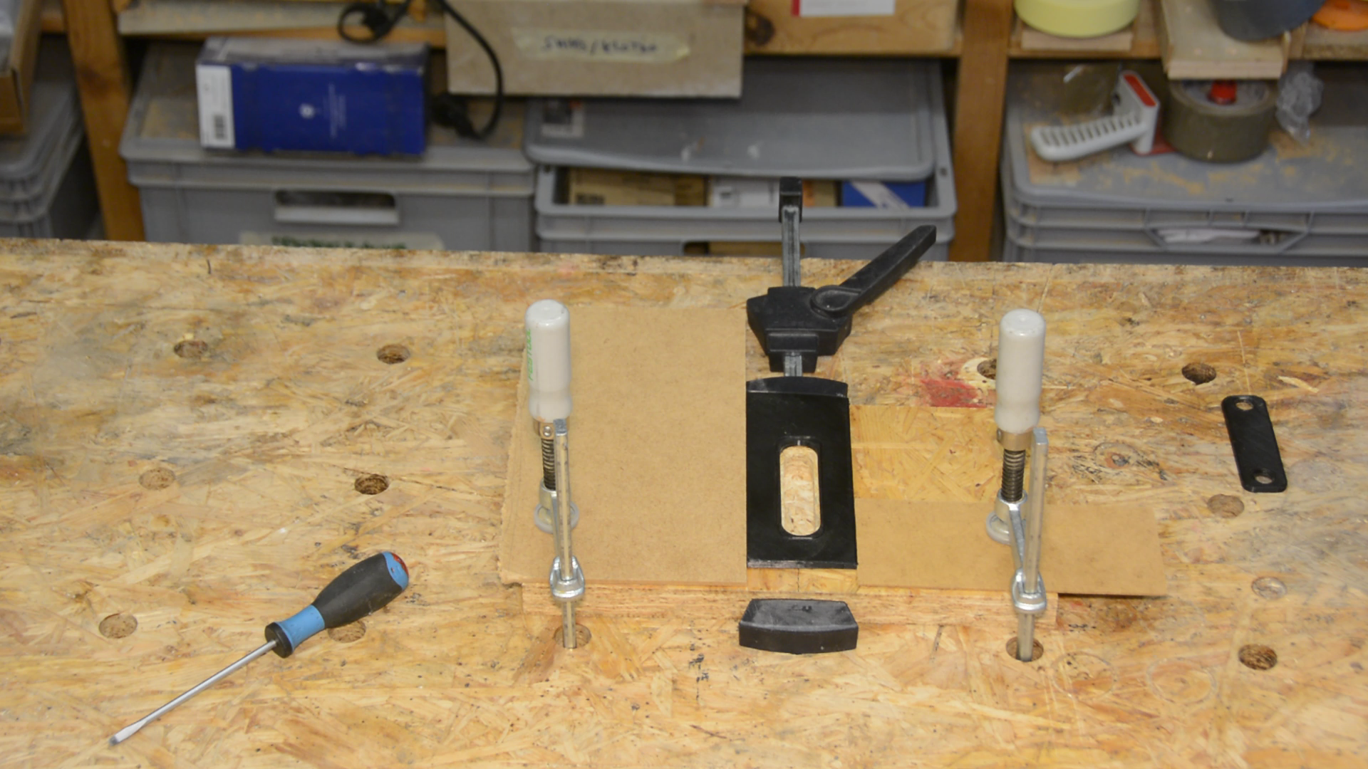
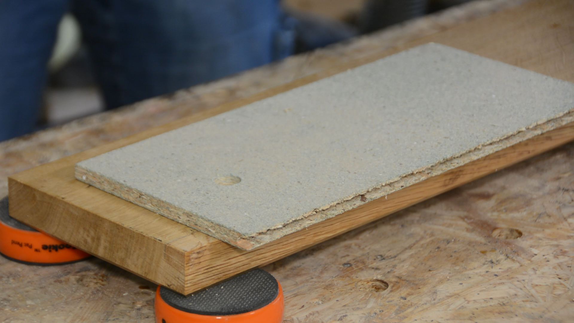
Let’s put these prints to use on a test piece of wood. With the size of the main template I stayed on the cheap side and printed it rather small. We have to support the sides of the template for the lack of contact surface between the jig and the board.
Clamping supporting thin strips of MDF next to it increases the stability quite a lot.
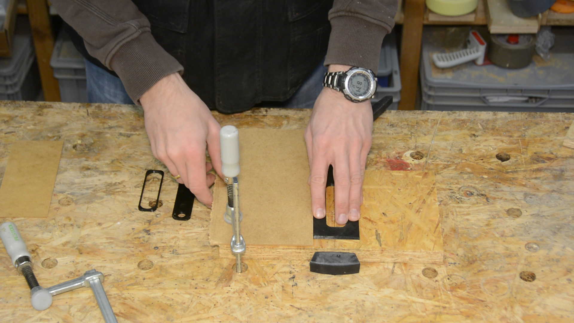
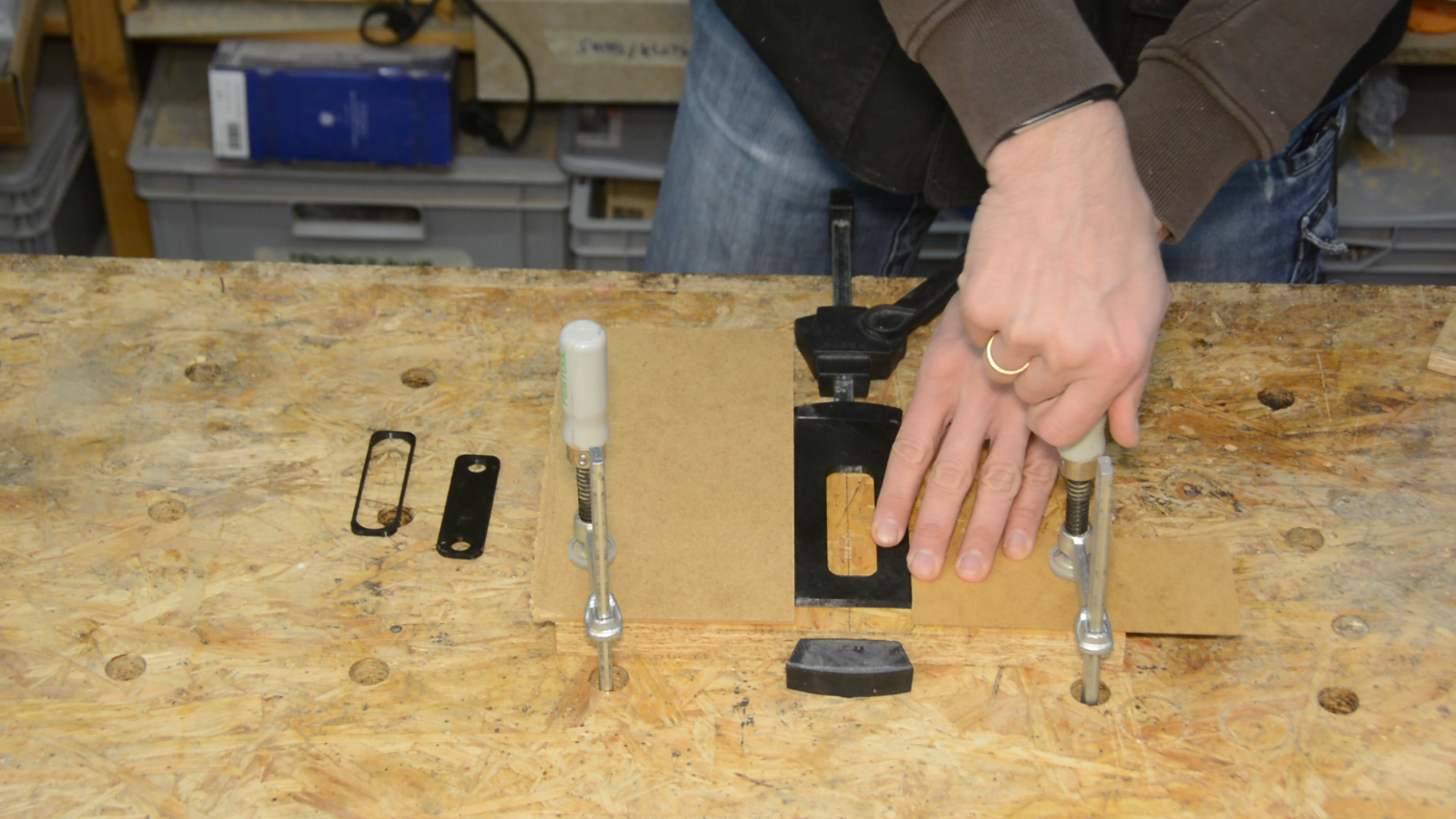
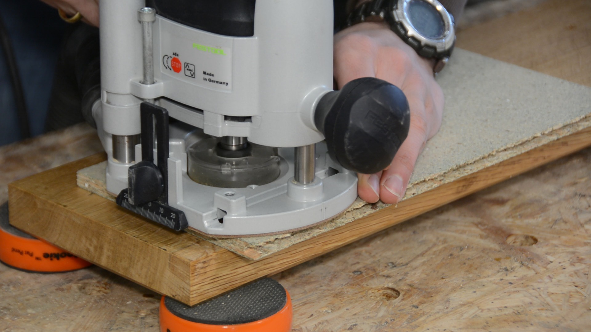
We can now set the router to 1.5mm depth and route away everything within the first template.
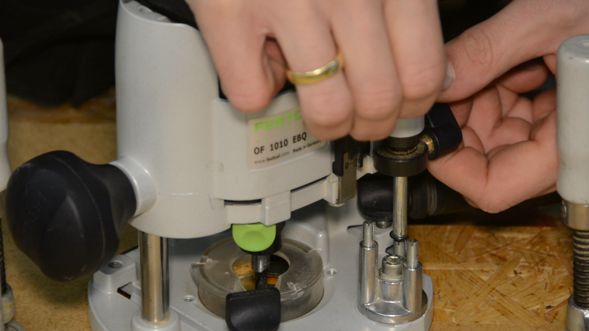
As a next step I add template 3 into template 1 and bore the 2 holes all the way through the board.


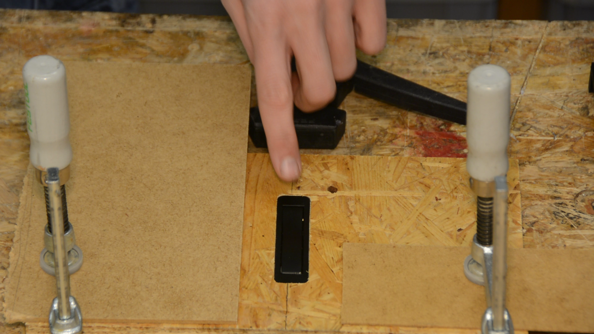
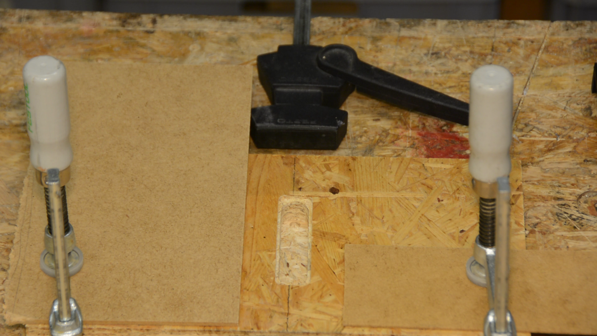
When the work on template 3 is finished I just snap in the thin frame of template 2 and remove the necessary 12 mm in several passes.
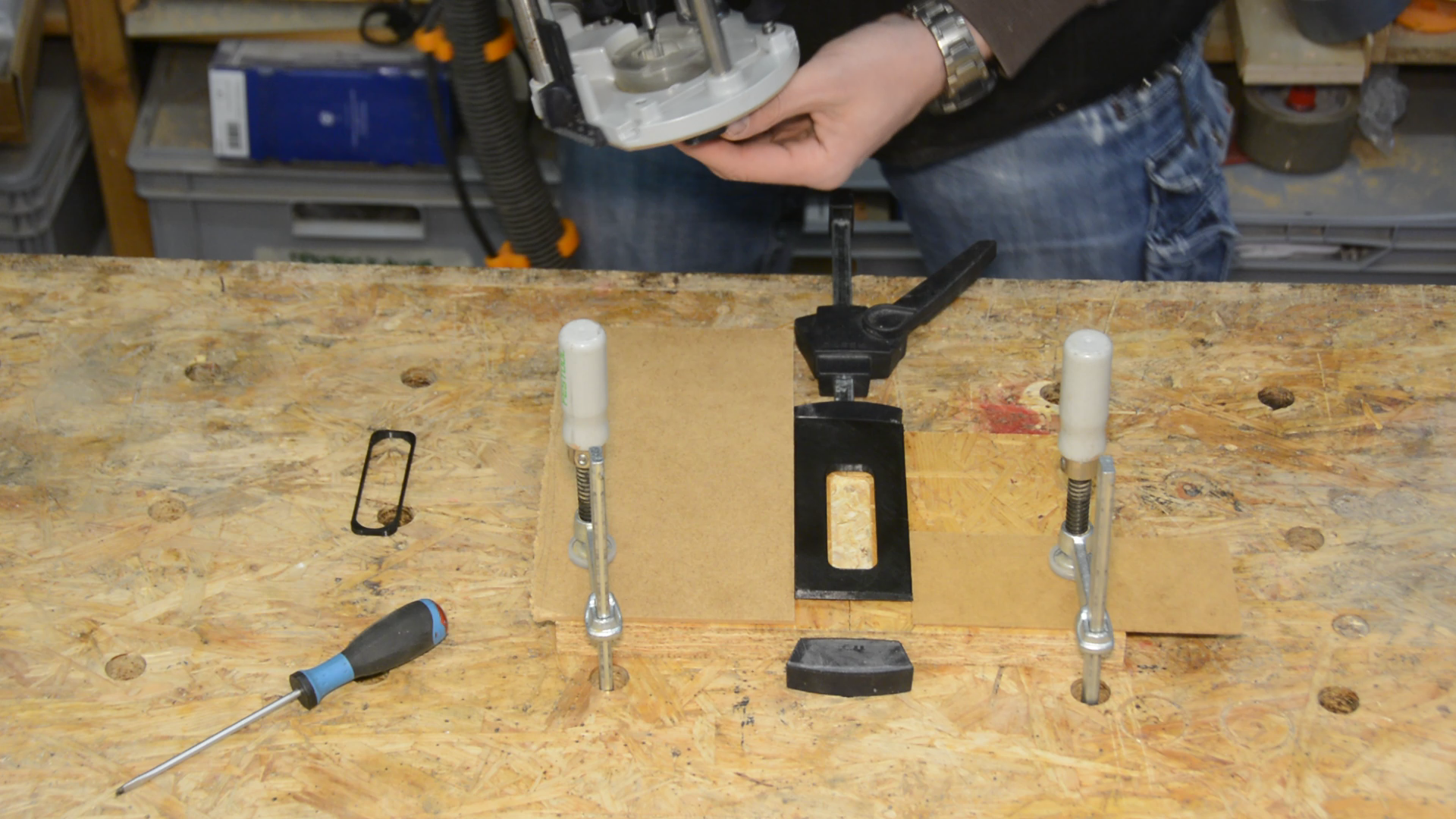
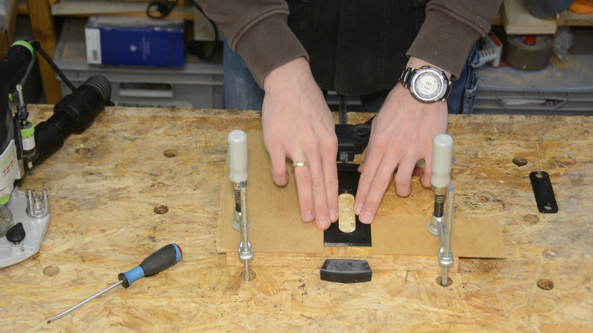
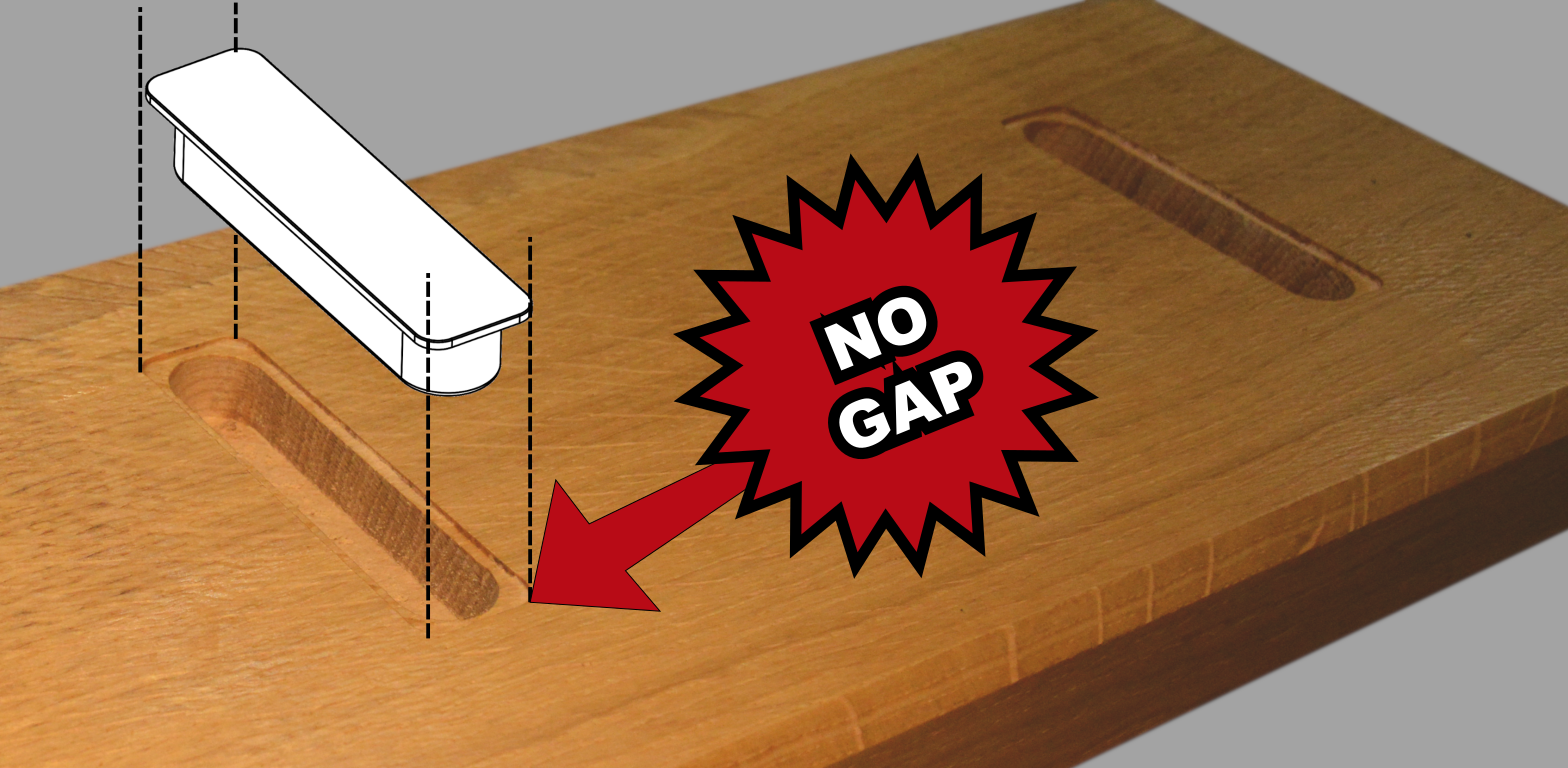
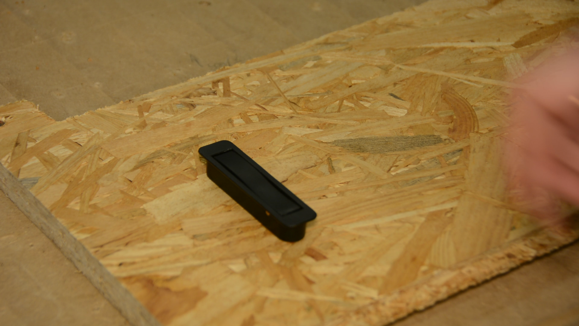
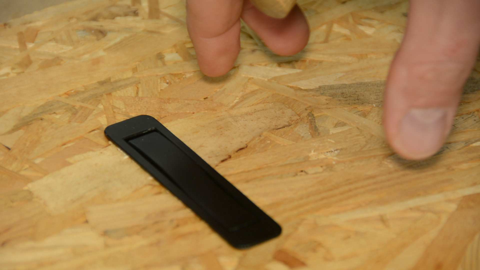
Let’s remove the jig and see if it fits. … Like a glove. There is no gap and the hook sits perfectly flush with the surface.
Finishing the board
In the meantime the CNC also finished it’s job. We can remove the dust, remove the screw and the wedge that has hold the piece in place.
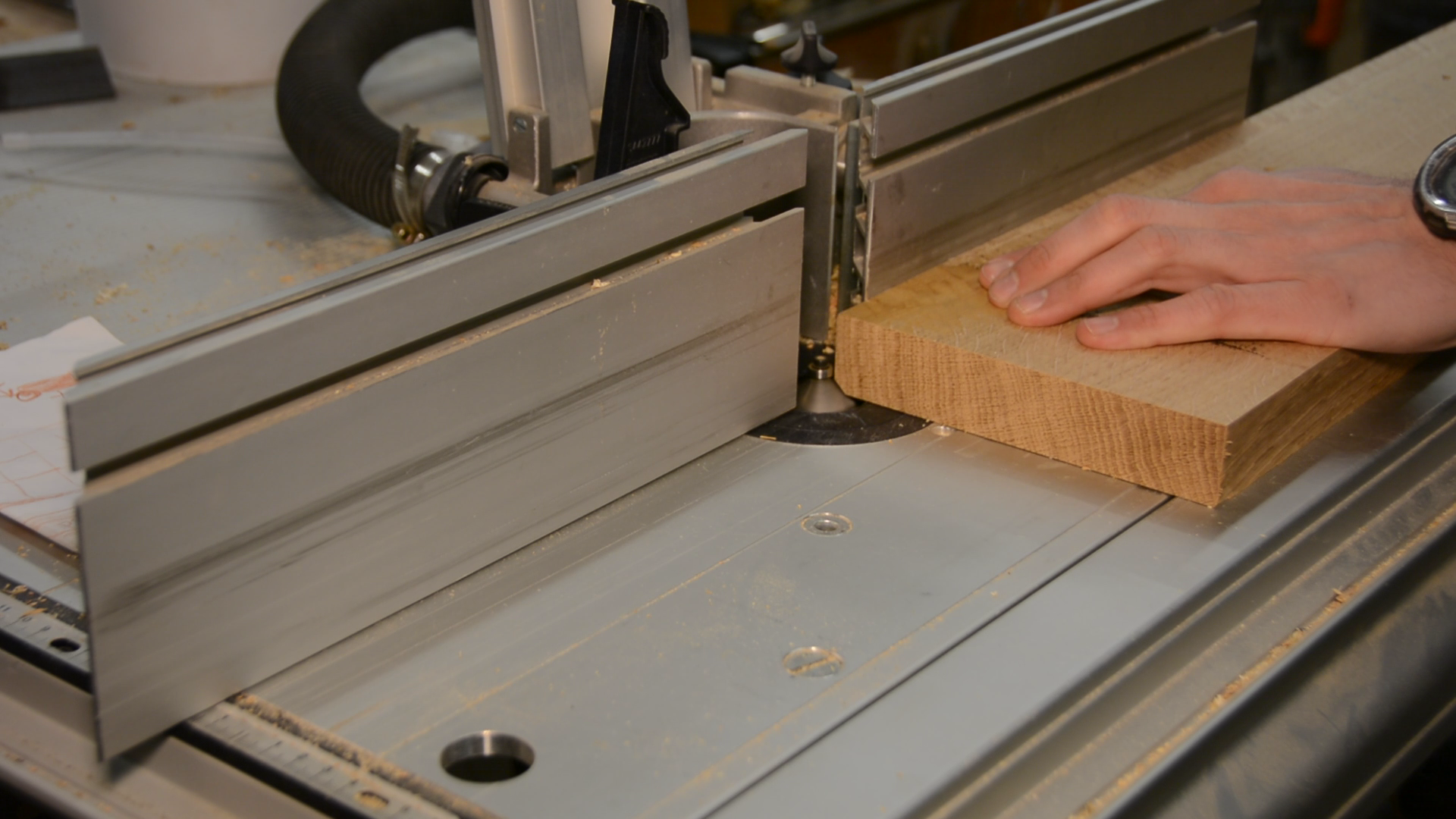
On the table saw I cut the board to its final width and length.


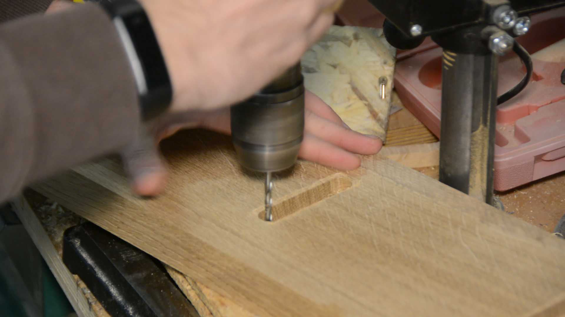
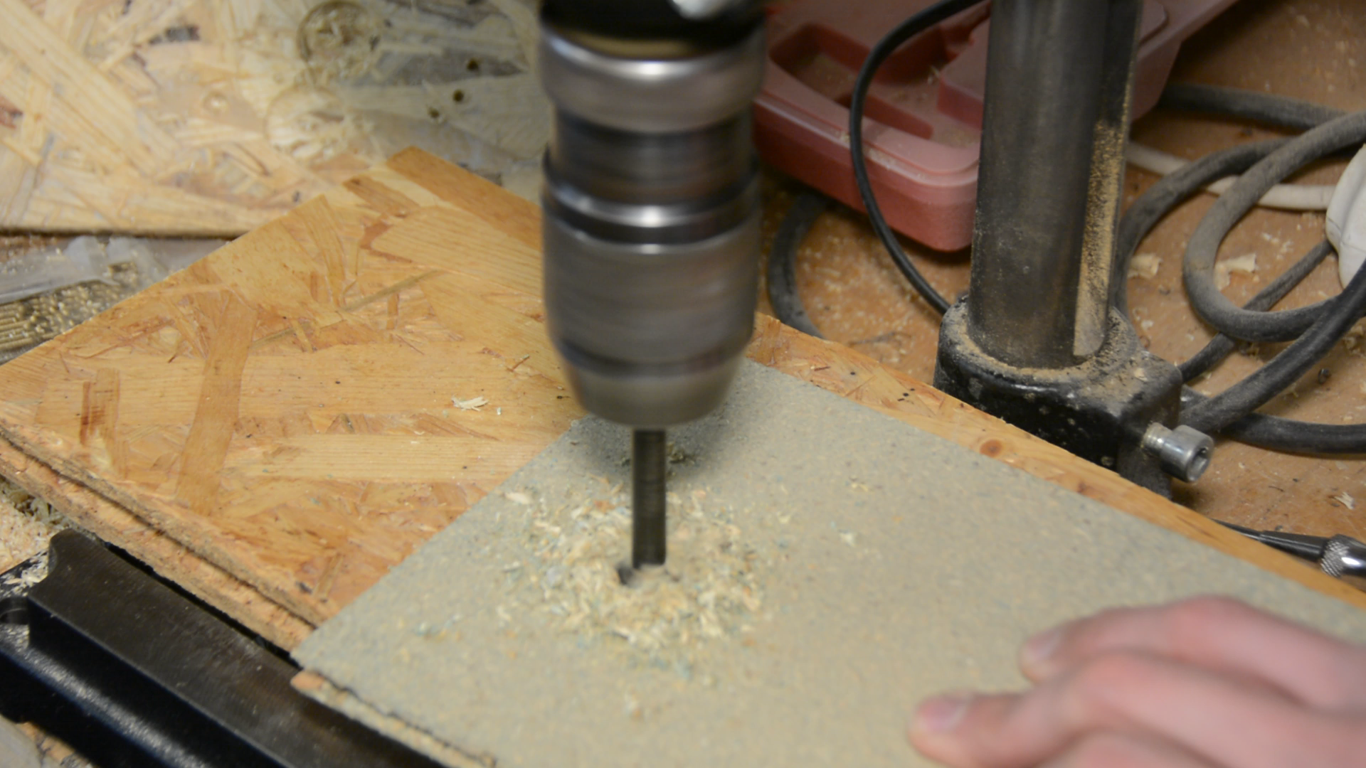
As the endmill on the CNC was not long enough I have to finish the mounting holes on the drill press.
In order to ease the edges and make the look a little less massive the board gets a chamfer on all four sides.
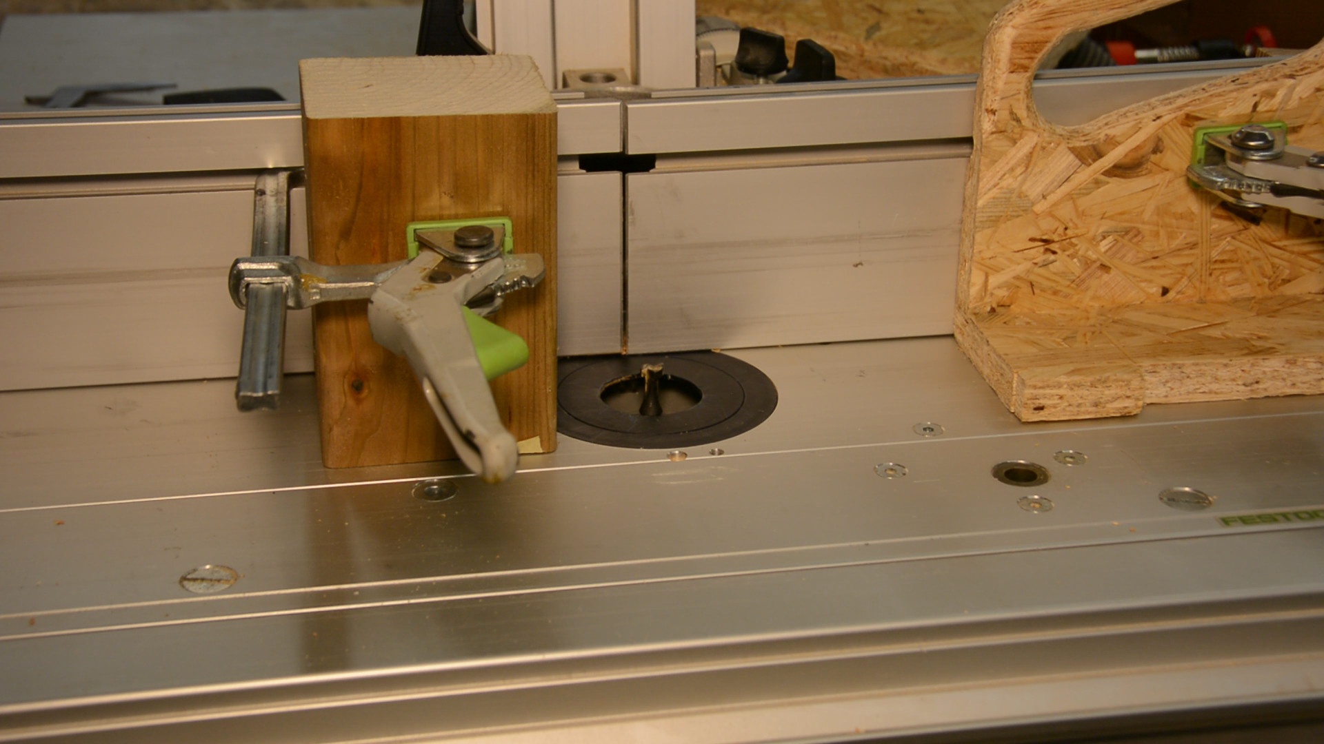
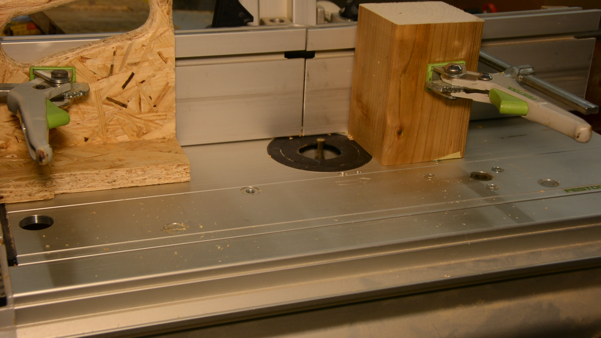
With two stops on the router table and a keyhole router bit I first route a keyhole in one side.

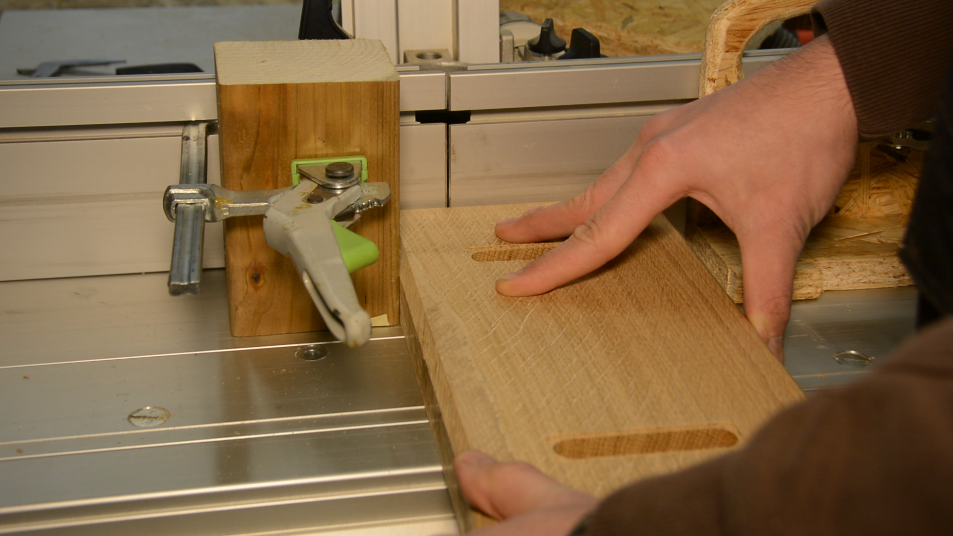
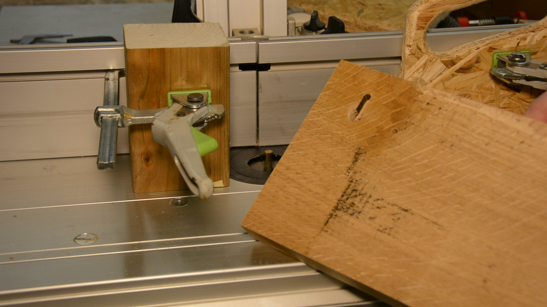
After changing the position of the stops the other side gets the same treatment.
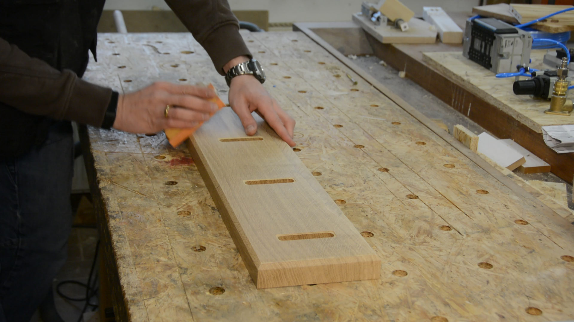
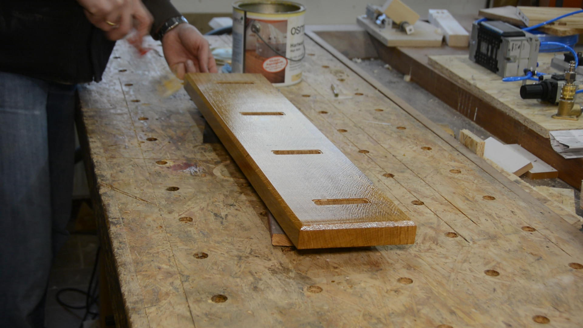
The surface is after the planing already in a pretty good shape so it only needs a light hand sanding and then gets two coats of hard wax oil.
One last router template – not 3d printed this time
Before we can put the screws into the hooks we have to counterbore for the screw heads. To do so I use again the router and the simplest possible template.
This template is a simple 17mm hole in a scrap piece of wood.
The hole is aligned with the center of the 4.5mm holes so that we can counterbore a hole of the right size using a 10mm bit in the router.

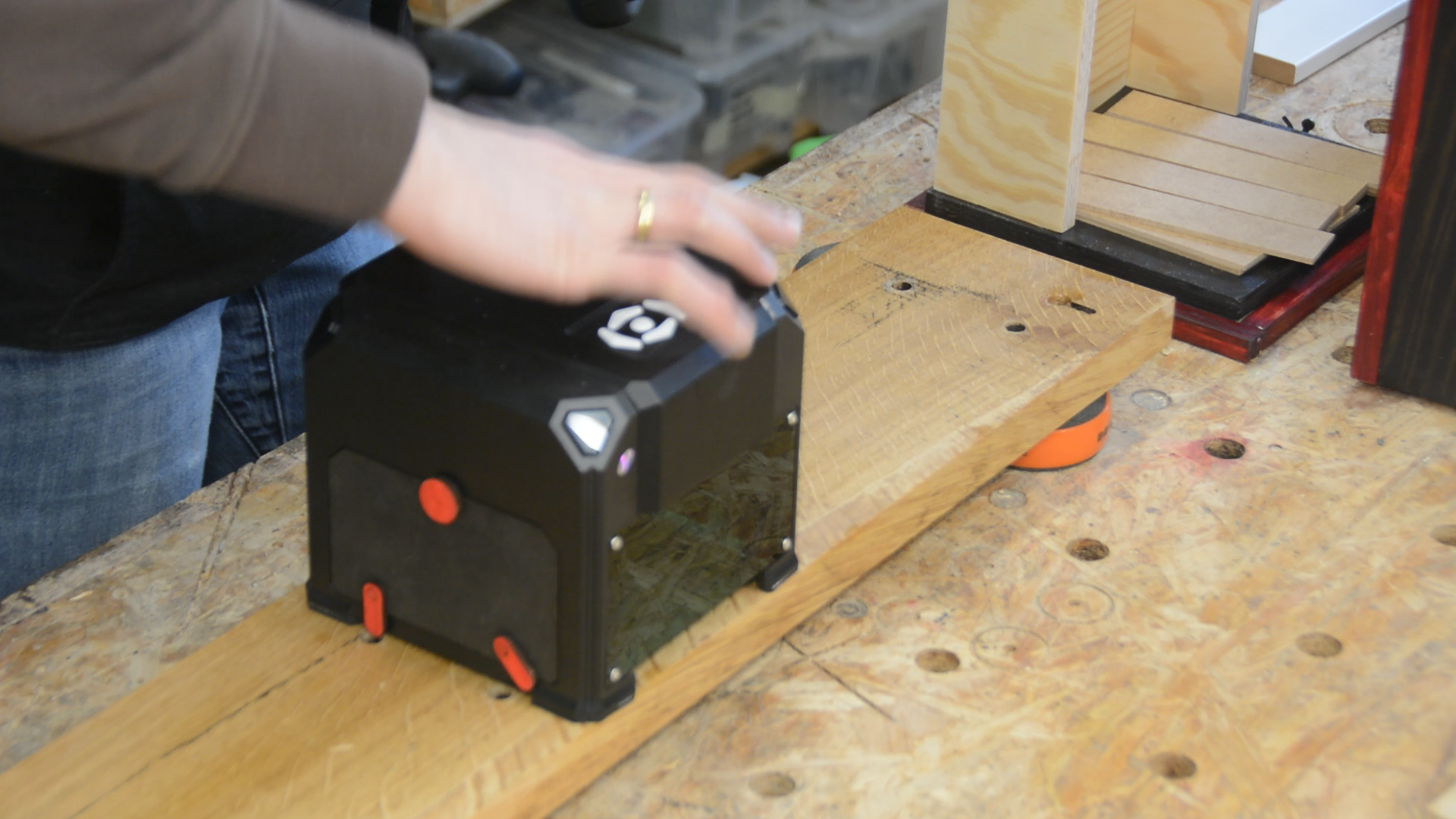
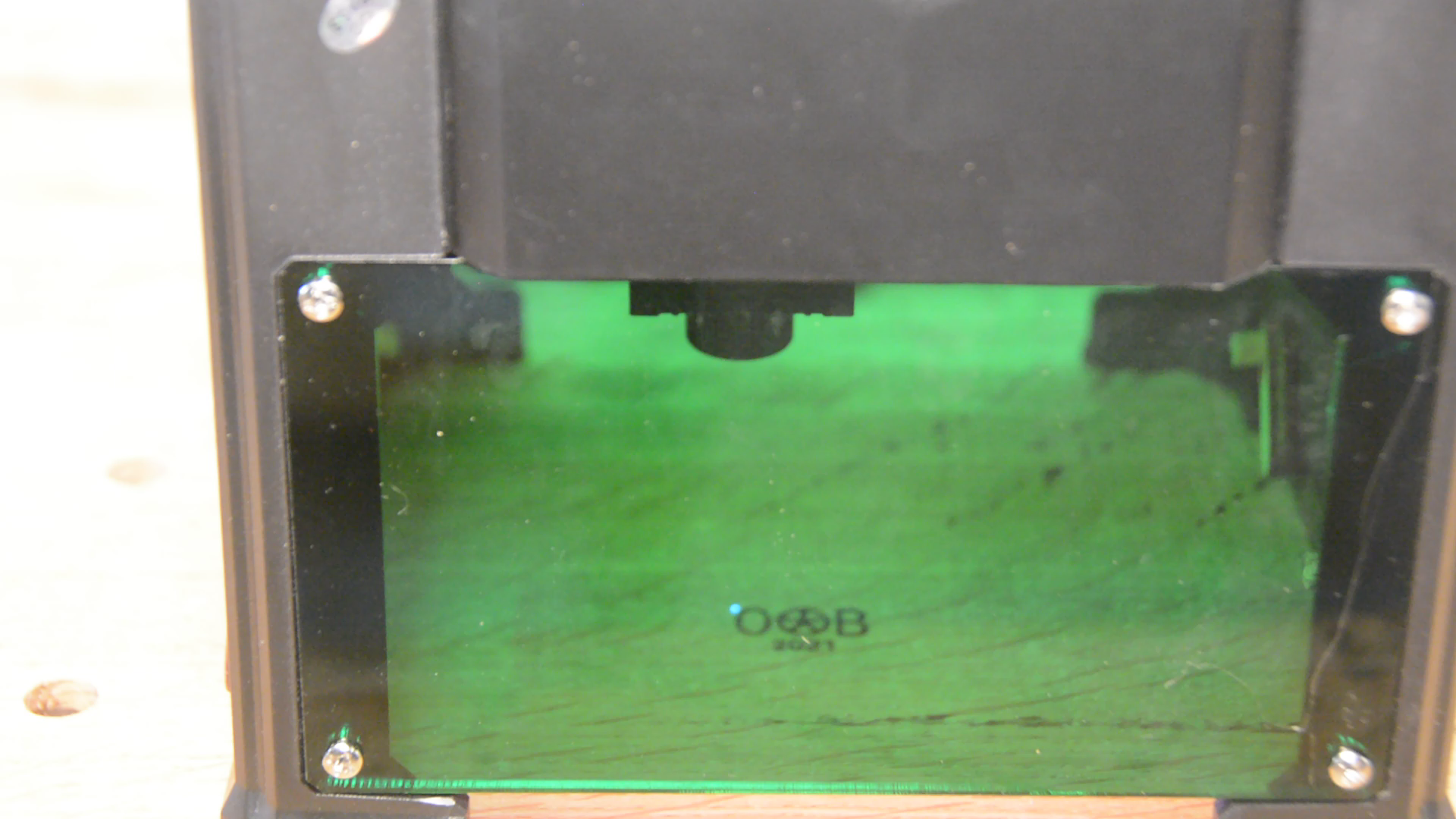
Lastly I apply my maker mark with the mini laser. It’s really convenient that this machine does not require a connection to the computer and can be used in the workshop.
Let’s now hang this piece at it’s place. A really great improvement!
