
In this article we are going to create a woodworking cutlist and cut diagrams from a FreeCAD model.
Installing and modifying A2plus workbench
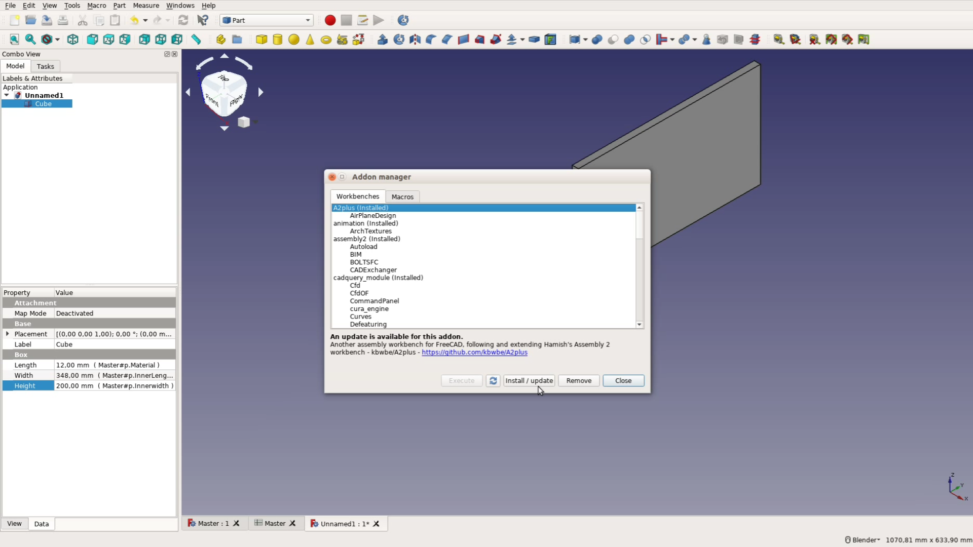
Before getting started we have to install the A2plus workbench by going to Tools – Addons, then select the workbench and install it.
After installing the workbench go to the website link in the description and follow the instructions below:
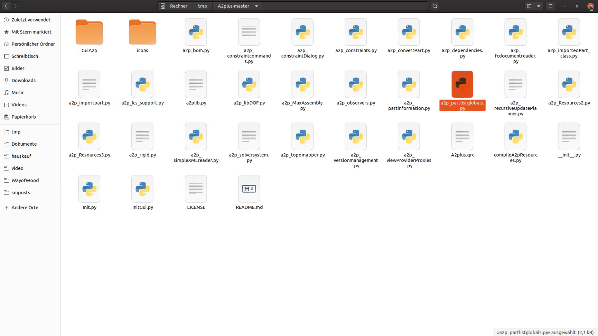
The files from the a2 plus workbench are in the following folders:
- For Windows: C:\Users\\AppData\Roaming\FreeCAD\Mod\A2plus
- For Linux: ~/.FreeCAD/Mod/A2plus
First modification: In the directory where the Assembly 2+ workbench is installed replace the file a2p_partlistglobals.py with the one that you can download here.
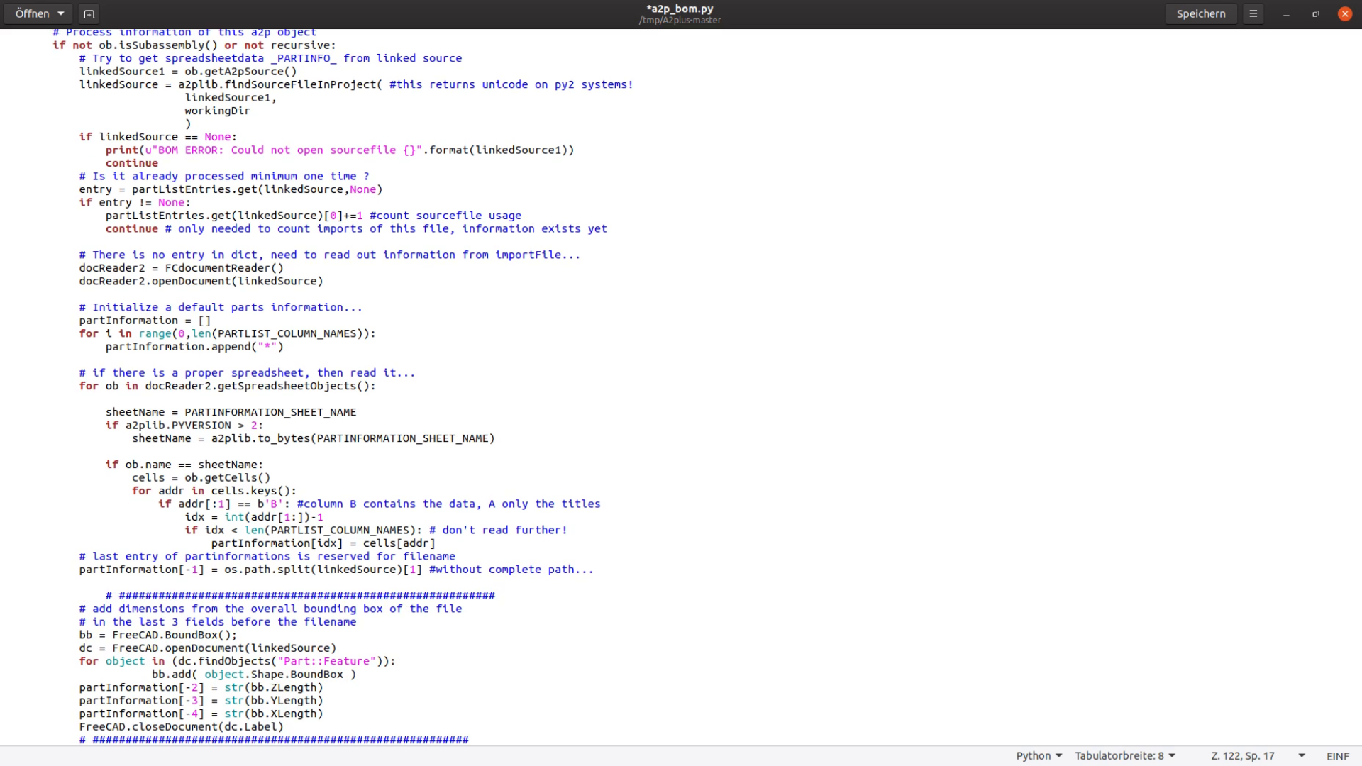
Second modification: You will also have to modify the file a2p_bom.py in the same directory. Look for the following two lines in the file. In the current version these lines start at line 113:
 # last entry of partinformations is reserved for filename
partInformation[-1] = os.path.split(linkedSource)[1] #without complete path...
After these two lines paste the following code:
	    # #########################################################
            # add dimensions from the overall bounding box of the file
            # in the last 3 fields before the filename
            bb = FreeCAD.BoundBox();
            dc = FreeCAD.openDocument(linkedSource)
            for object in (dc.findObjects("Part::Feature")):
	               bb.add( object.Shape.BoundBox )
            partInformation[-2] = str(bb.ZLength)
            partInformation[-3] = str(bb.YLength)
            partInformation[-4] = str(bb.XLength)
            FreeCAD.closeDocument(dc.Label)
	    # #########################################################
This will add the dimensions of each board in the table discussed later in the article.
After restarting FreeCAD we are good to open the japanese toolbox from the last part of the tutorial.
Creating the cutlist in FreeCAD
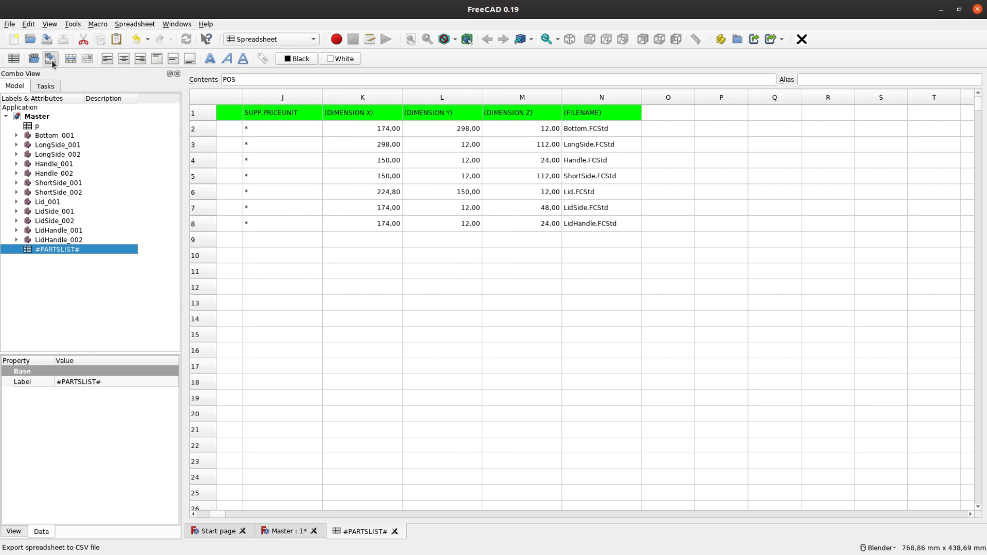
After all this preparation work the creation of the cutlist is actually quite simple. Just click on the “Part List” button in the Assembly 2plus workbench and a part list is created as a new spreadsheet. Now we open this spreadsheet and export it as a csv file with the export button in the spreadsheet workbench.
Download the WayofWood_Cutlister Spreadsheet from the resource section of the website and open it with the application of your choice. Here we use LibreOffice — but Excel or Google Docs should work as well.
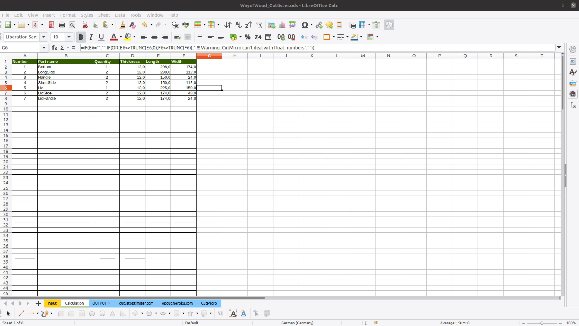
Open the csv file and copy the data from the file into the spreadsheet in the table Input and overwrite the sample data.

In the table calculations we can check if there are any warnings. In our case there is one warning that CutMicro can’t cope with float numbers. So let’s go back to the Input sheet and round this number.

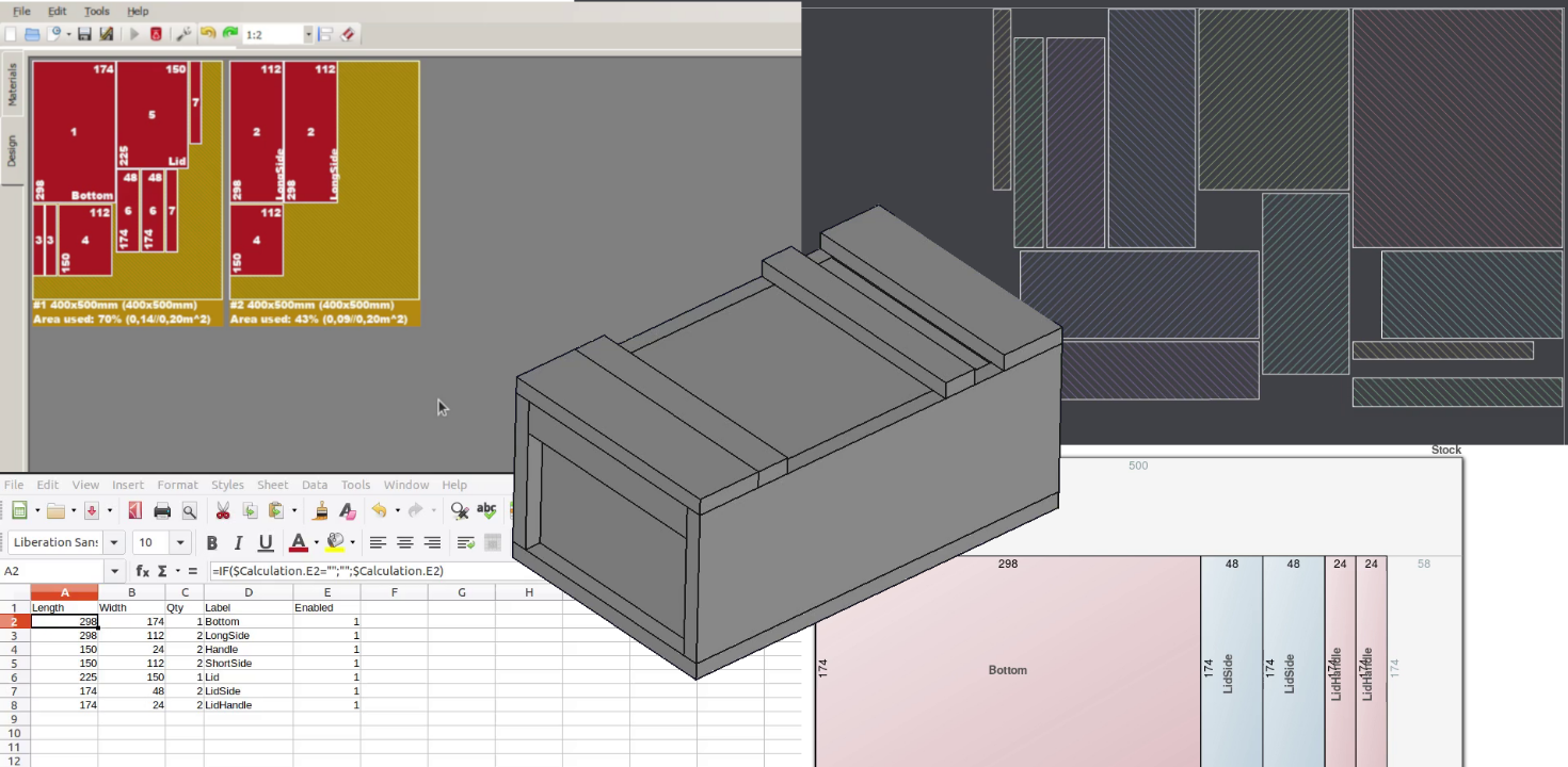
With everything prepared we can start to convert the cutlist in a cut diagram.
From Cutlist to Cut diagram in 3 different ways
Let’s now have a look at the three output tabs. The spreadsheet contains three output formats for three different tools.
Cutlistoptimizer
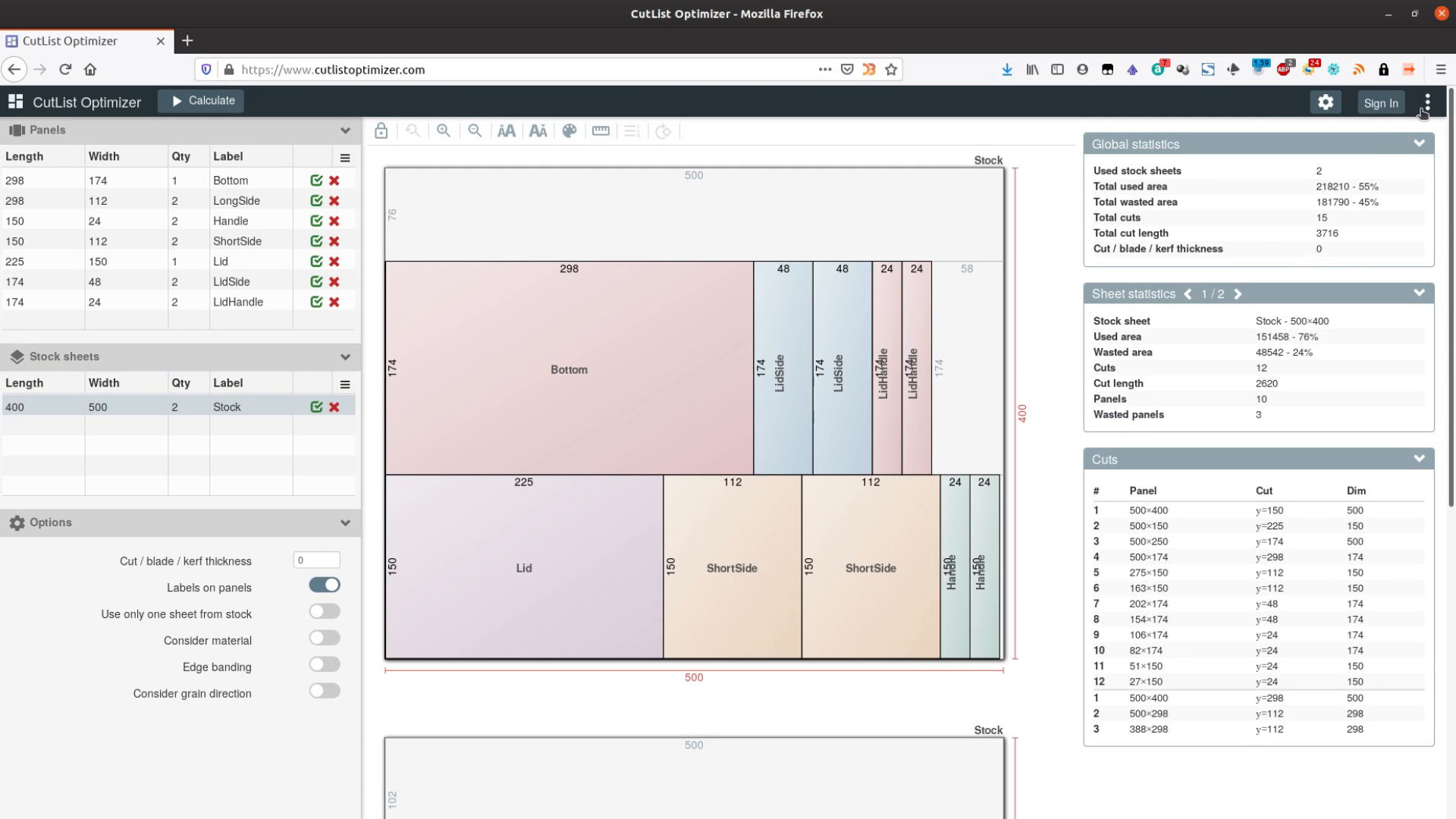
The first one is cutlistoptimizer.com. It’s a software that is as of now free to use but it is not open source so the conditions for its usage might change in the future.
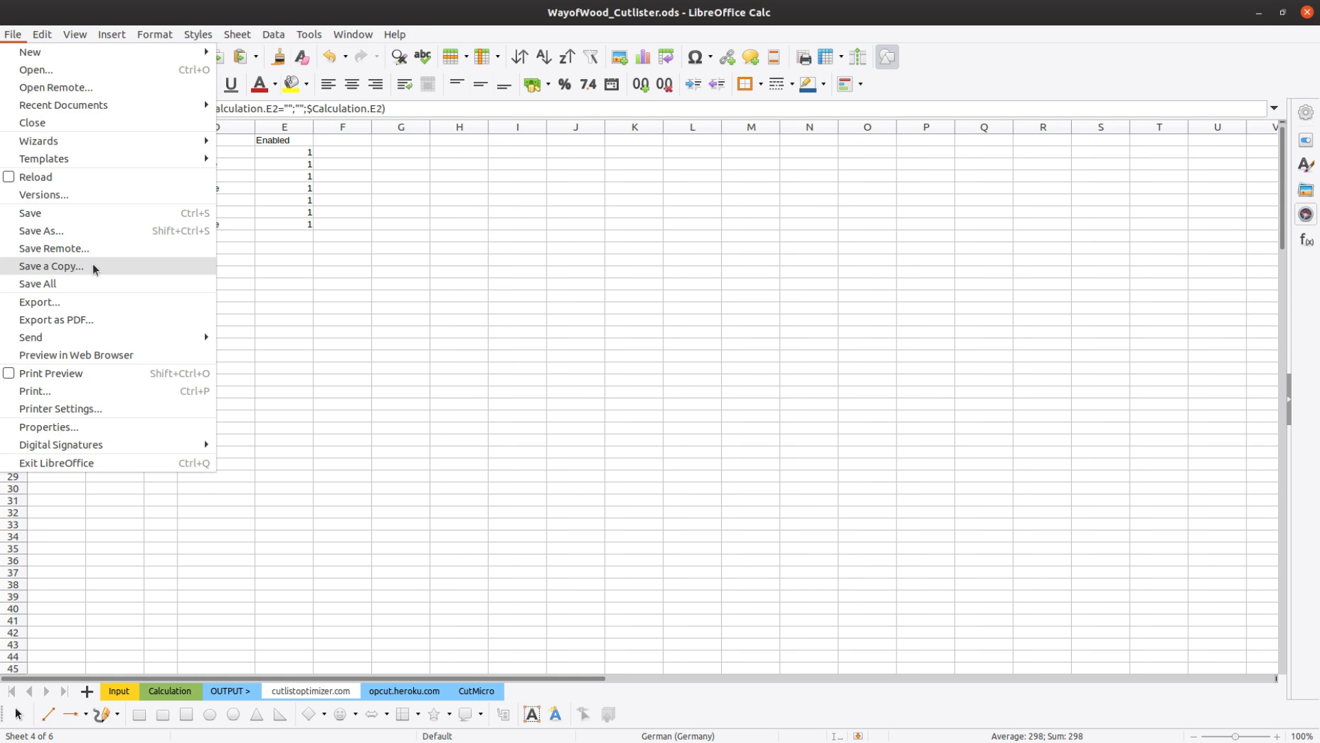
Go to the respective tab and save a copy as a CSV file.
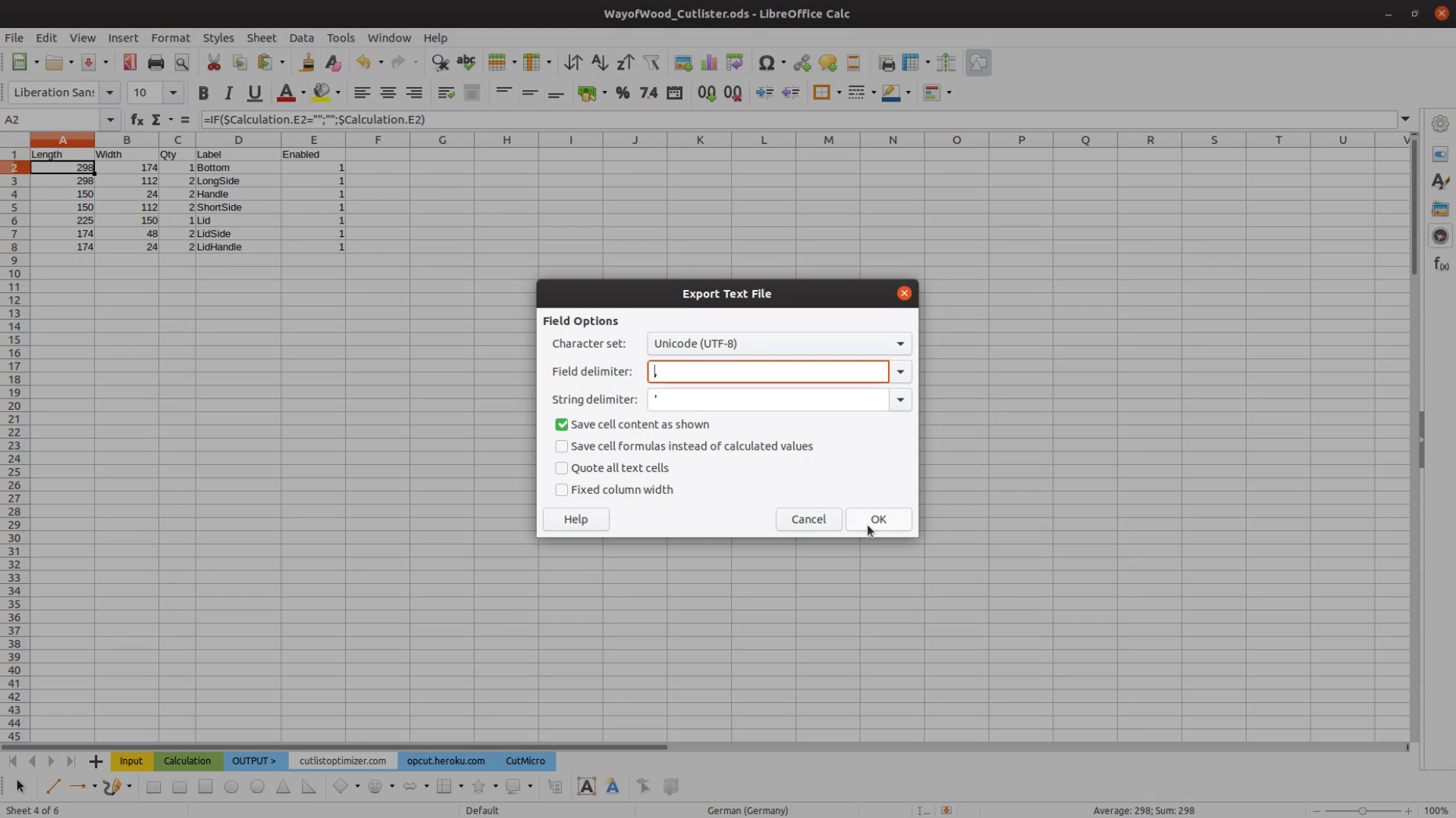
Make sure you select the “Edit filter settings” checkbox and that the items are separated by comma.
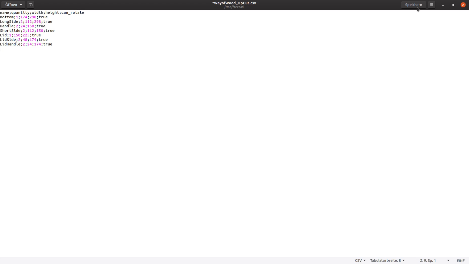
Open the file in a text editor and remove the empty lines.

On cutlistoptimizer.com we create a few panels that we have in stock. Next we import the csv file and hit the calculate button.After the calcluation is done we can
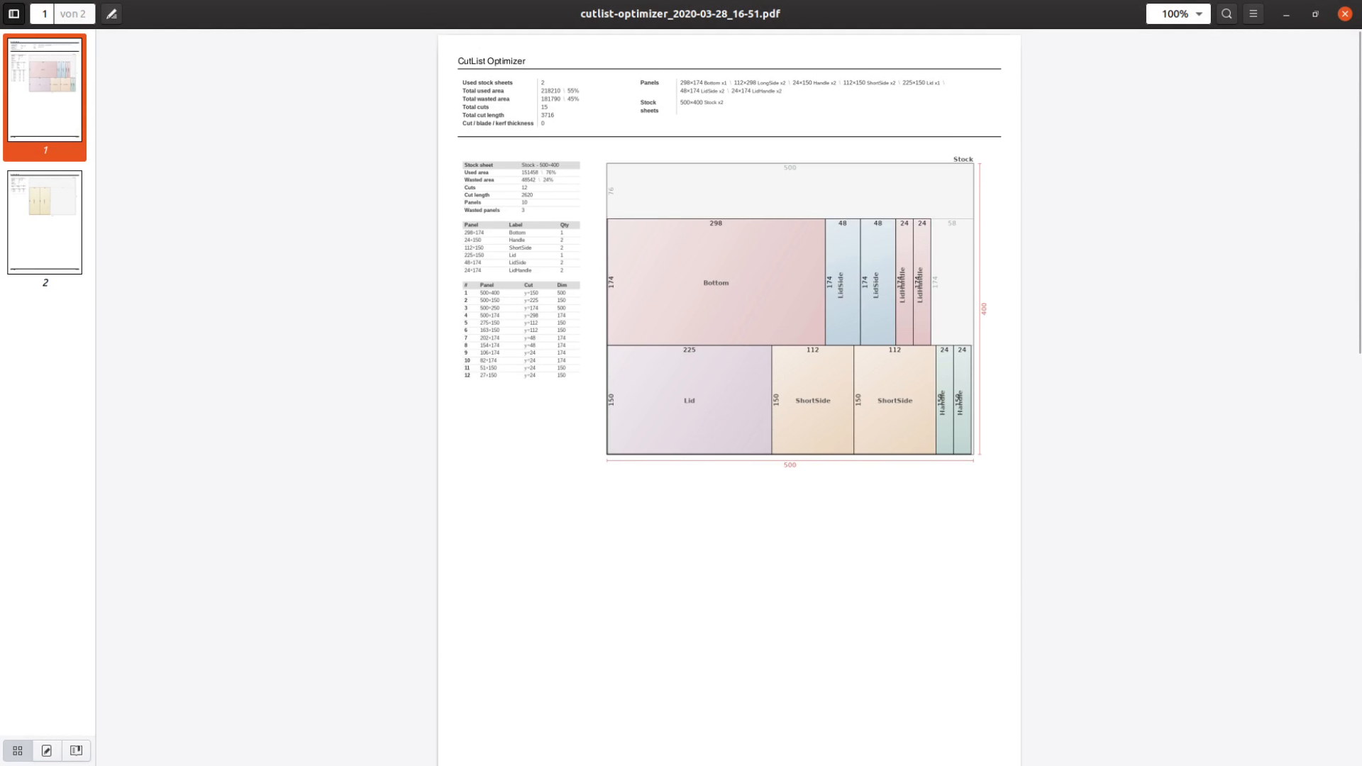
export the file as PDF, print it and take it to the table saw.


Cutlistoptimizer is great but as the website could go down or start to charge money for their service let’s look at two alternative solutions.
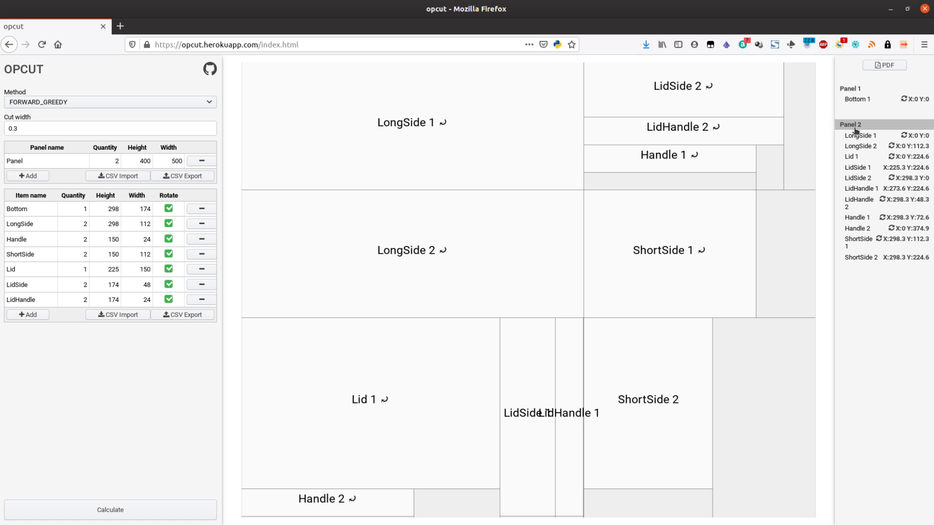
Opcut
Opcut is open source software. We export the csv file for opcut by separating the entries with a semicolon.

Again we delete the empty lines in a text editor.
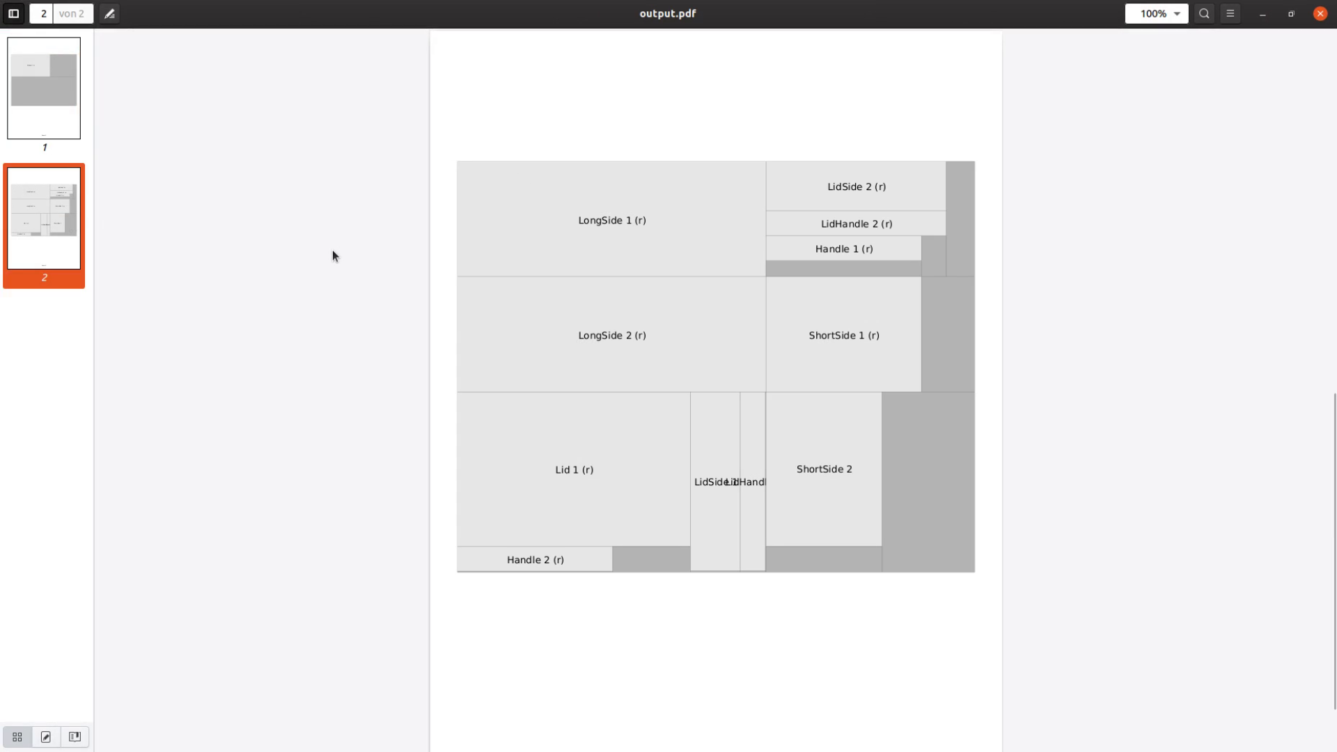
Opcut is available at opcut.herokuapp.com. It’s interface is not as nice as the one from cutlistoptimizer but it get the job done. We again create two panels and then import the csv file. After hitting the calculate button we can take a look at the result and export a PDF.
CutMicro
The last tab is for CutMicro. We save this tab as CSV.

The delimiter doesn’t matter but the string delimiter is important.
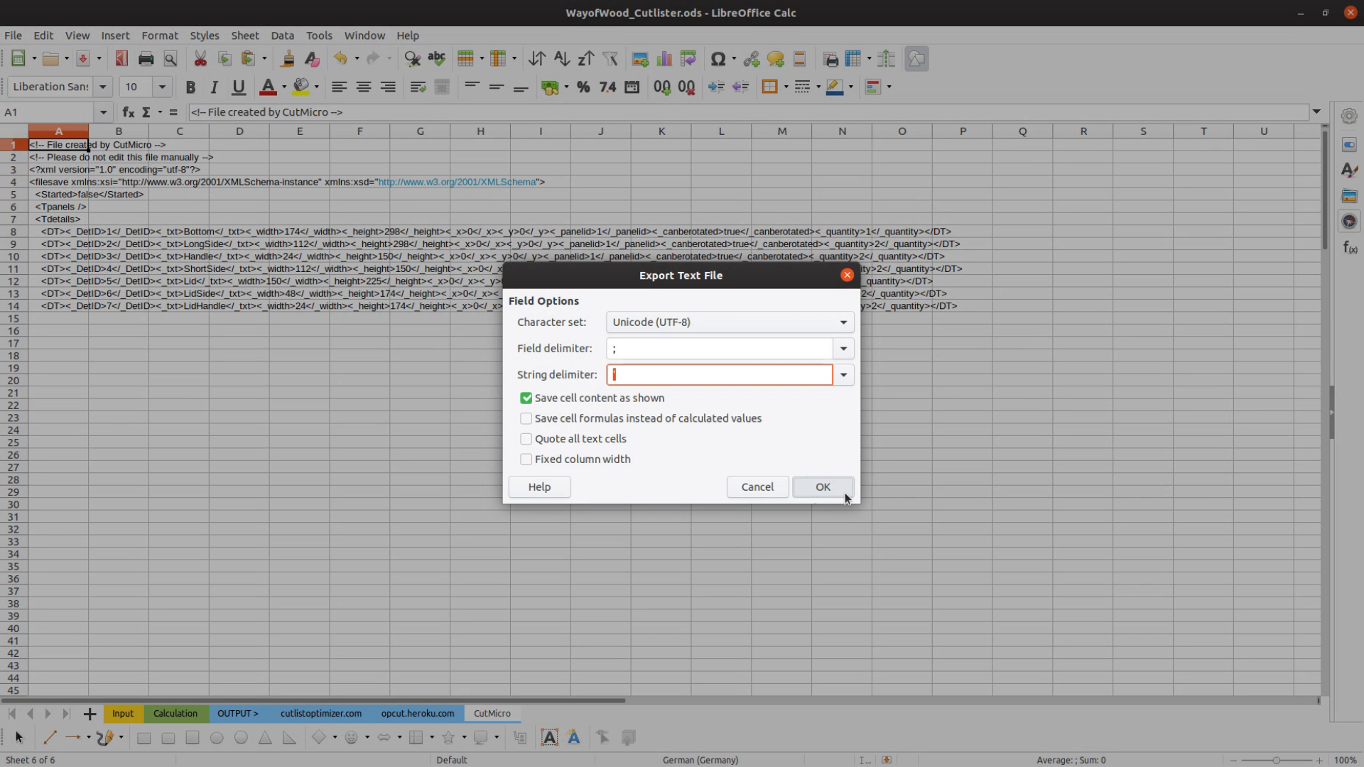
After saving the file the file extension has to be changed from csv to cpxml.

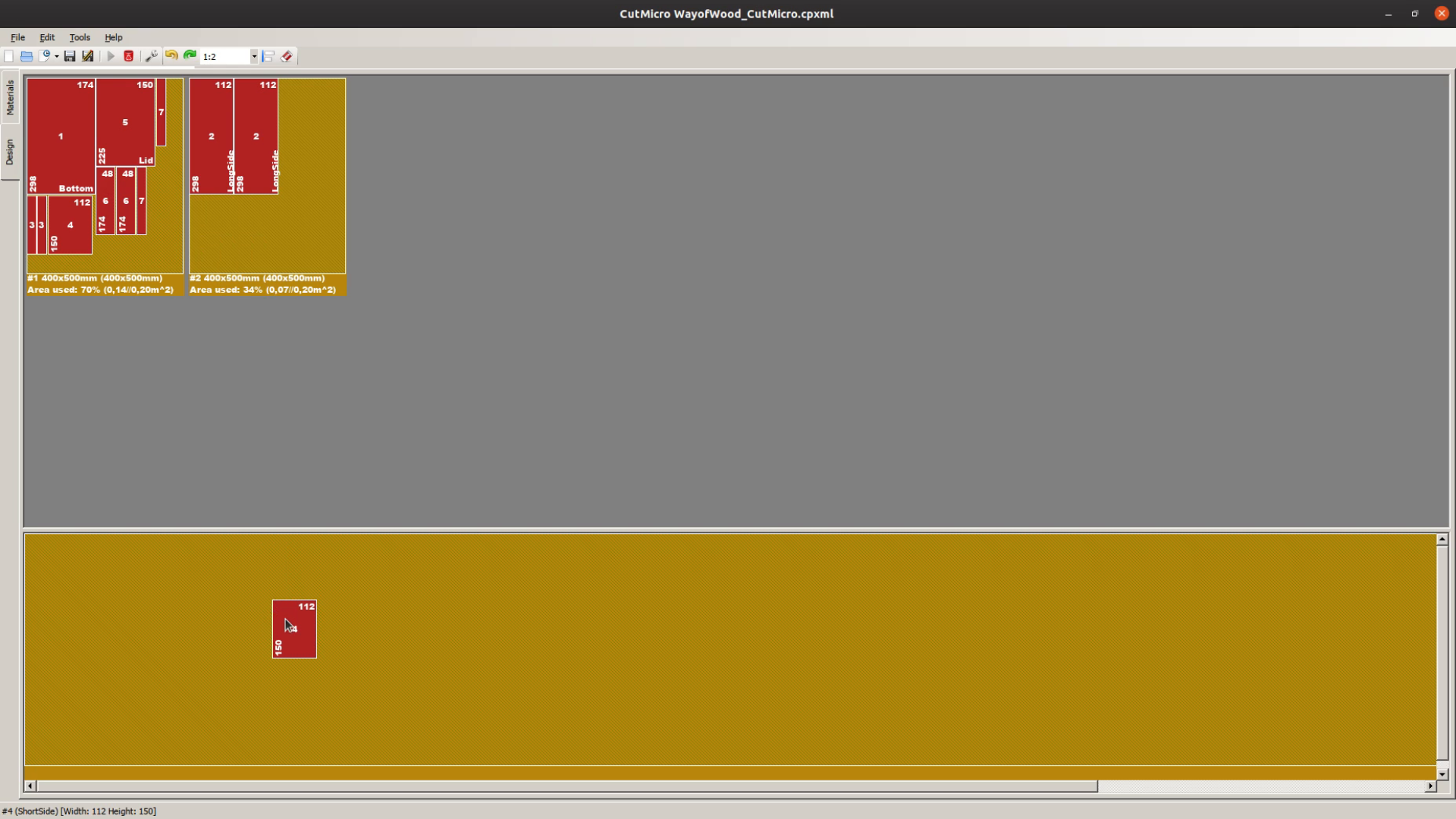
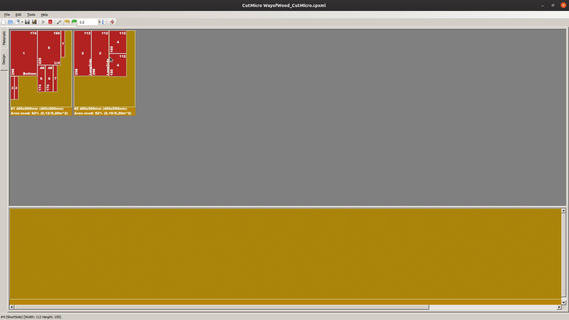
In CutMicro we open the XML file and create two new panels.

After hitting the play button we go to the design tab. Now select Tool – Auto Place to automatically place the pieces onto the panels. The nice thing about CutMicro is that you can interactively rearrange the panels. Under Linux the export and print functions are not working but taking a screen shot works quite well.
Cutlist for the CNC or Laser cutter
All these methods are optimized for using the table saw. If you are looking for a way to use the CNC or the laser cutter the process is slightly different.
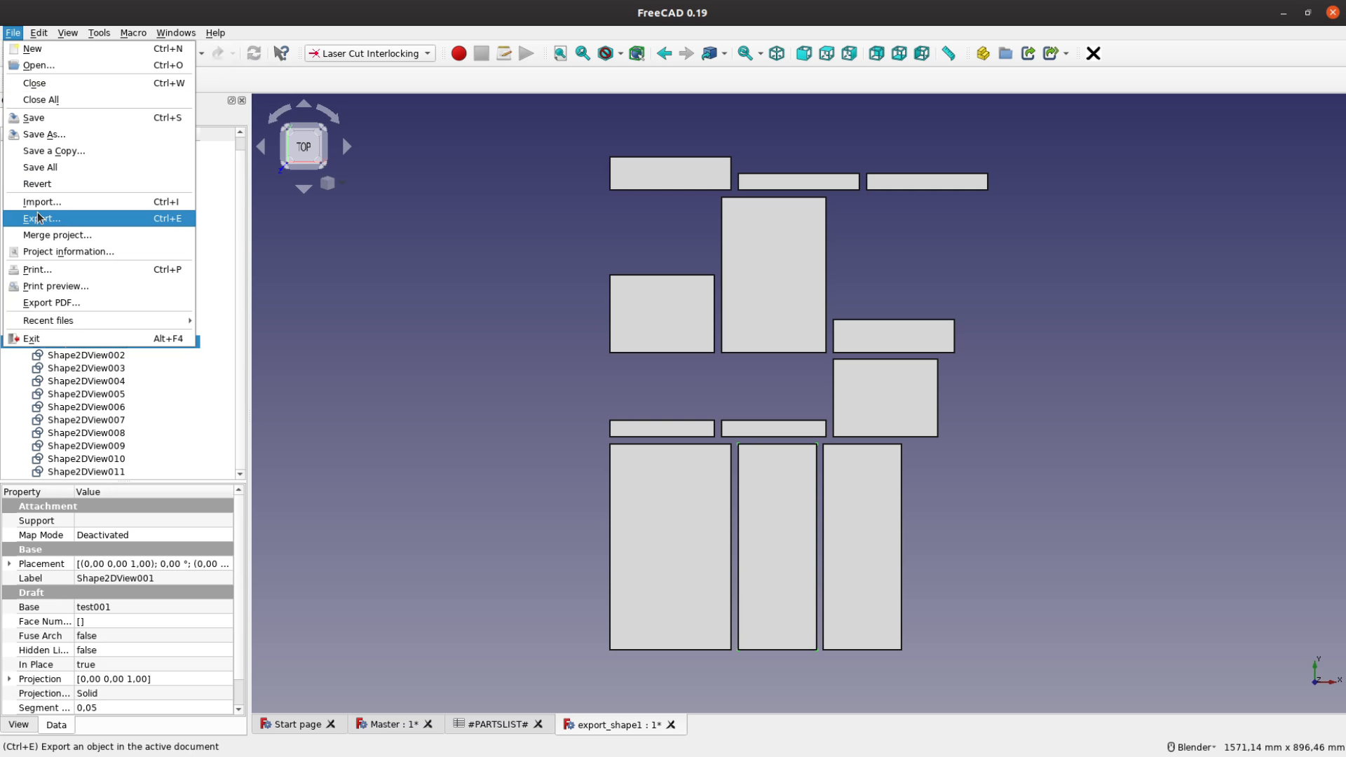
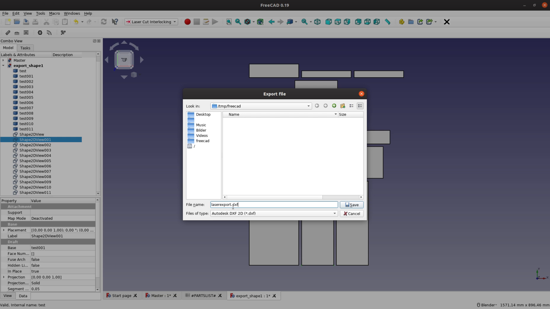
In the Lasercut Interlocking workbench we place all the pieces flat side by side. Each shape is then exported as a dxf file.
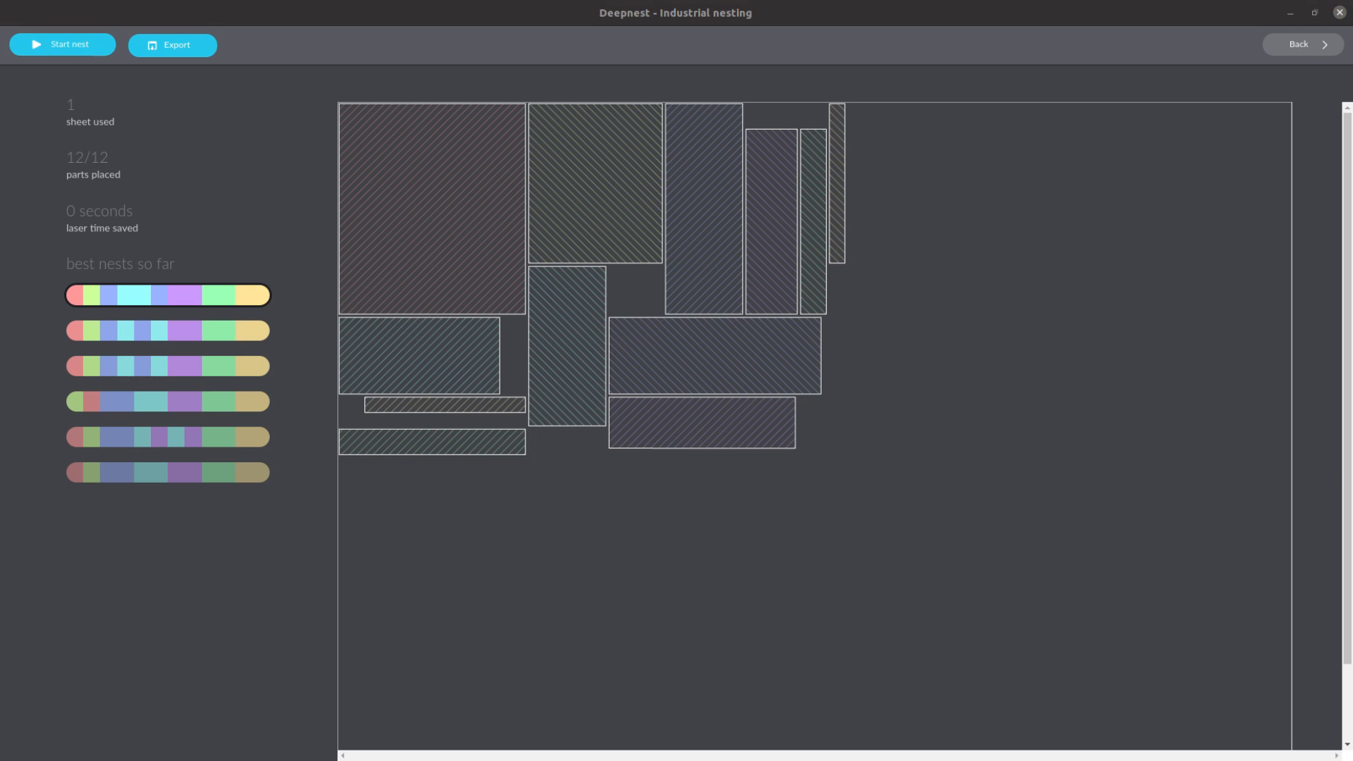
We import these files in deepnest.io. The software optimized their placement and we export the resulting file as SVG. The only downside of this tool is that the resulting cut diagrams can’t be cut on a table saw as you can’t run a cut across the sheet. But for a laser it’s perfect.
Resources
- WayofWood_Cutlister Spreadsheet

This was great and helped me down the path to figuring out my cut list. There is one problem I was having with the code. If I had a Datum (plane in my case) it would return invalid length (infinite – ish)
when I changed it to the following it worked every time
at the beginning add
import Part
and then around 113 of a2p_bom.py change it to
# #########################################################
# add dimensions from the overall bounding box of the file
# in the last 3 fields before the filename
dc = FreeCAD.openDocument(linkedSource)
op = Part.makeCompound([i.Shape for i in dc.findObjects(“Part::Feature”) if i.ViewObject.Visibility and not i.TypeId == “PartDesign::Plane”])
bb = op.BoundBox
partInformation[-2] = str(bb.ZLength)
partInformation[-3] = str(bb.YLength)
partInformation[-4] = str(bb.XLength)
FreeCAD.closeDocument(dc.Label)
# #########################################################
this ignores objects that aren’t visible and not datum planes.
it works by making a temporary compound object and using the bounding box for that. this will work on irregular shapes as well.
That’s a good point. Thanks for the extension.
i just tried to modify the bom.py file but FreeCAD reports me the following failure:
19:37:18 invalid character in identifier (a2p_bom.py, line 125)
19:37:18 Traceback (most recent call last):
File “”, line 68, in Initialize
I tried it with both of your variants.
Am i missing something?
Python is very picky about the amount and the type of space in front of a line. Maybe this causes a problem?
Otherwise the change should be pretty straightforward.
This series on FreeCAD was perfect. I watched your initial video on CAD alternatives for wood working and then the series on using FreeCAD. I was able to become proficient at using FreeCAD within a few hours of study. Much more to learn, but building out parts, assembling them, and then creating a cut out diagram is perfect. From US and using US measurements is a little awkward in FreeCAD, but doable. Thanks for the great instructional video
Thanks for the comment. Great that the series was helpful for you. Are there any aspects you are still missing?
Great tutorials! I’m loving the Freecad tool and hopefully will begin to create stuff out of it.
I’d love to see a tutorial on how to create complex wood joints within freecad. I’m a bit puzzled by the fact that we should create separate files for each wooden part, and therefore that could complicate the drawing of wood joints. It would be great if you could do some video covering that topic 🙂
Moreover, it looks like the Opcut tool isn’t available online. Do you know if there’s another mirror or alternative website hosting the tool?
Good catch that opcut is not longer online. I don’t know a mirror but you could download the code and run it locally: OpCut
Regarding the joints I normall don’t model them in detail but might look at the topic for a future tutorial.
This is great. I tried importing the spreadsheet into Excel and Google docs, but Excel complained about an error in the file and Google docs gave me a ton of #ERROR!! messages in a few columns. It looks like, in your ‘Calculation’ sheet, some of the formulae start with ‘==’ instead of ‘=’. Fixing this manually makes it work in Excel and Google.
Great point. Thanks a lot!
Thanks for the great tutorial on A2plus! Have tried it and with FreeCAD 0.19 the #PARTLIST# doesn’t work any longer. Based on Python Error Message FreeCAD.closeDocument(dc.Label) is just the name without file extension and therefore fails.
I changed the statement to FreeCAD.closeDocument(dc.Name) which made it work again. Hope this helps.
Great tip. Thank you!
it’s October 2022 – following difrections but not finding the file paths after installing the add-on . . . let alone the path shown to find it as in the description – not a power linux user- but can follow directions – unfortunately the issue everytime is everyone is working with a different scenario then theirs in which it was written — not sure where to go with this
Thanks for the tutorial, it works really well. I can now use my existing material much better.
However, I had to make a few small changes so that it works for me.
For me the files are in the folder (Linux Mint 21.1 and I use the Freecad 20.2 appimage):
/home//.local/share/FreeCAD/Mod
You may still need to show hidden files.
in the A2p_BOM.py you have to replace as TF wrote (thanks for the tip) the line
FreeCAD.closeDocument(dc.Label)
with the line
FreeCAD.closeDocument(dc.Name):
In the a2p_partlistglobals.py
you have to enter the names from a2p+ 4.60 on in the following format:
PARTLIST_COLUMN_NAMES = [
translate(“A2p_BoM”, “IDENTNO”),
translate(“A2p_BoM”, “DESCRIPTION”),
translate(“A2p_BoM”, “SUPPLIER”),
translate(“A2p_BoM”, “SUPP.IDENTNO”),
translate(“A2p_BoM”, “SUPP.DESCRIPTION”),
translate(“A2p_BoM”, “SUPP.URL”),
translate(“A2p_BoM”, “SUPP.PRICE”),
translate(“A2p_BoM”, “SUPP.PRICEUNIT”),
translate(“A2p_BoM”, “(DIMENSION X)”),
translate(“A2p_BoM”, “(DIMENSION Y)”),
translate(“A2p_BoM”, “(DIMENSION Z)”),
translate(“A2p_BoM”, “(FILENAME)”)
]
Thanks for the tutorial, it works really well.
I can now use my existing material much better.
I had to make a few small changes so that it works for me.
For me the files are in the folder (Linux Mint 21.1 and I use the Freecad 20.2 appimage):
/home//.local/share/FreeCAD/Mod/A2plus
You may still need to show hidden files.
in the A2p_BOM.py you have to replace as TF wrote (thanks for the tip)
the line FreeCAD.closeDocument(dc.Label)
with the line FreeCAD.closeDocument(dc.Name)
In the a2p_partlistglobals.py you have to enter the names from a2p+ 4.60 on in the following format: PARTLIST_COLUMN_NAMES = [
translate(“A2p_BoM”, “IDENTNO”),
translate(“A2p_BoM”, “DESCRIPTION”),
translate(“A2p_BoM”, “SUPPLIER”),
translate(“A2p_BoM”, “SUPP.IDENTNO”),
translate(“A2p_BoM”, “SUPP.DESCRIPTION”),
translate(“A2p_BoM”, “SUPP.URL”),
translate(“A2p_BoM”, “SUPP.PRICE”),
translate(“A2p_BoM”, “SUPP.PRICEUNIT”),
translate(“A2p_BoM”, “(DIMENSION X)”),
translate(“A2p_BoM”, “(DIMENSION Y)”),
translate(“A2p_BoM”, “(DIMENSION Z)”),
translate(“A2p_BoM”, “(FILENAME)”) ]
hello, thanks a lot for this tutorial, i did it all for my first project with freecad and it worked flawlessly.
I would like to ask for some orientation if I wanted to add another variable to the partlist, say for instance the total perimeter of the boards im using??
I know some python but im rusty and i can not figure it out yet.
Thanks a lot again
I created a branch with the described changes here. Also included the fixes mentioned in the comments.
I added it as a separate function within this addon, so every user can choose among the standard and the CutList Optimizer parts list.
You will find it here: https://github.com/vwildi/A2plus/tree/feature/AddCutListOptimizer
Please feel free to mention any suggestions or other feedback.
Furthermore, I created a pull request to the official Assembly2+ repository to hope it will be added in one of the next versions.
You can find my pull request here: https://github.com/kbwbe/A2plus/pull/632
Note: The exported spreadsheet is delimited by tabs, however, CutList Optimizer expects commas instead to import the file accordingly.
Thanks a lot!
i am getting this error when I try to run A2plus in free cad.
I edited ‘a2p_partlistglobals’ as instructed.
19:25:03 cannot import name ‘CLO_PARTLIST_COLUMN_NAMES’ from ‘a2p_partlistglobals’ (C:\Users\t_hav\AppData\Roaming\FreeCAD\Mod\A2plus\.\a2p_partlistglobals.py)
19:25:03 Traceback (most recent call last):
File “”, line 84, in Initialize
File “C:\Program Files\FreeCAD 0.21\bin\Lib\site-packages\shiboken2\files.dir\shibokensupport\__feature__.py”, line 142, in _import
return original_import(name, *args, **kwargs)
File “C:\Users\t_hav\AppData\Roaming\FreeCAD\Mod\A2plus\.\a2p_BoM.py”, line 37, in
from a2p_partlistglobals import (