
In this article we make a stamp and show how easy it is to use digital fabrication methods such as the laser cutter, the CNC and a 3d printer.
Brett from skull and spade did a great video on how to create a stamp manually in this video. This was the inspiration to create a stamp with digital methods and to show that using the laser cutter, CNC and the 3D printer is not that difficult.
The stamp from linoleum
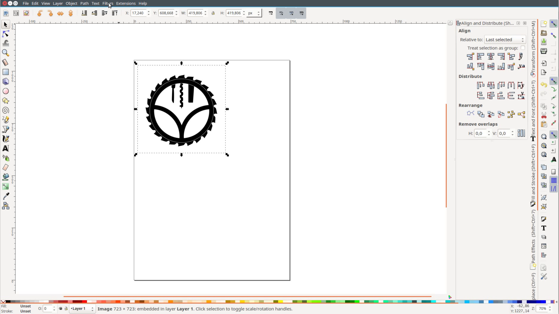
We create the stamp itself with the free software Inkscape that is similar to Illustrator:
First import the black and white image you want to convert into a stamp.
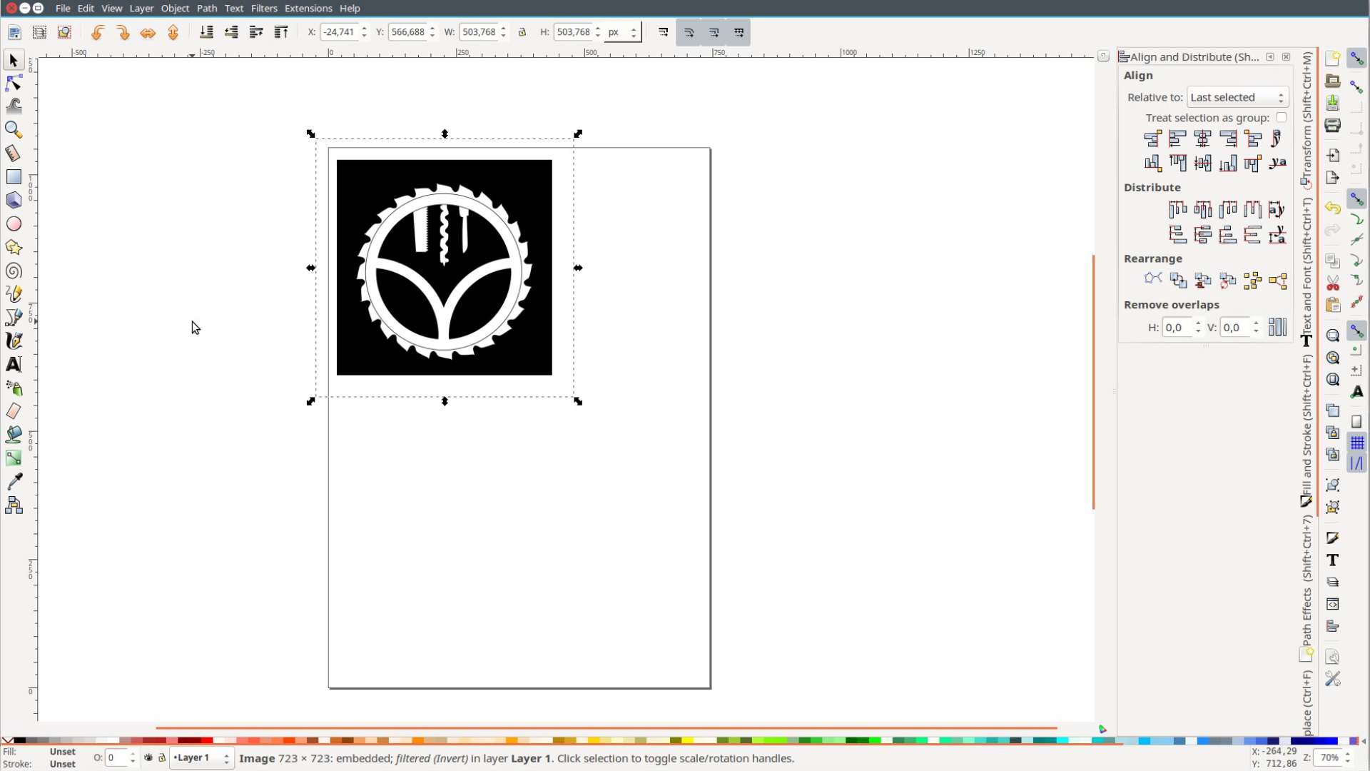
Second invert the colors by choosing Filters, Colors, Invert and make sure all boxes are selected. Then flip the image by pressing the button with the double-sided arrow.
Thirdly draw a red line around the image using the rectangle tool. Make it transparent by clicking on the cross mark and click on the red color while holding shift to select the stroke.
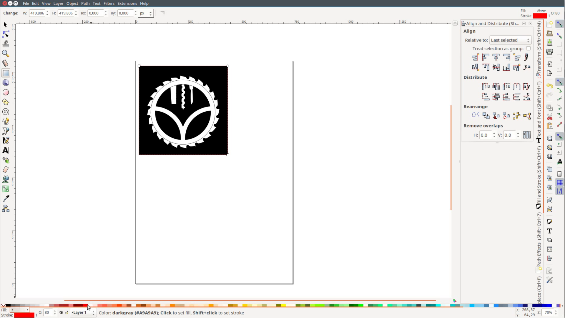
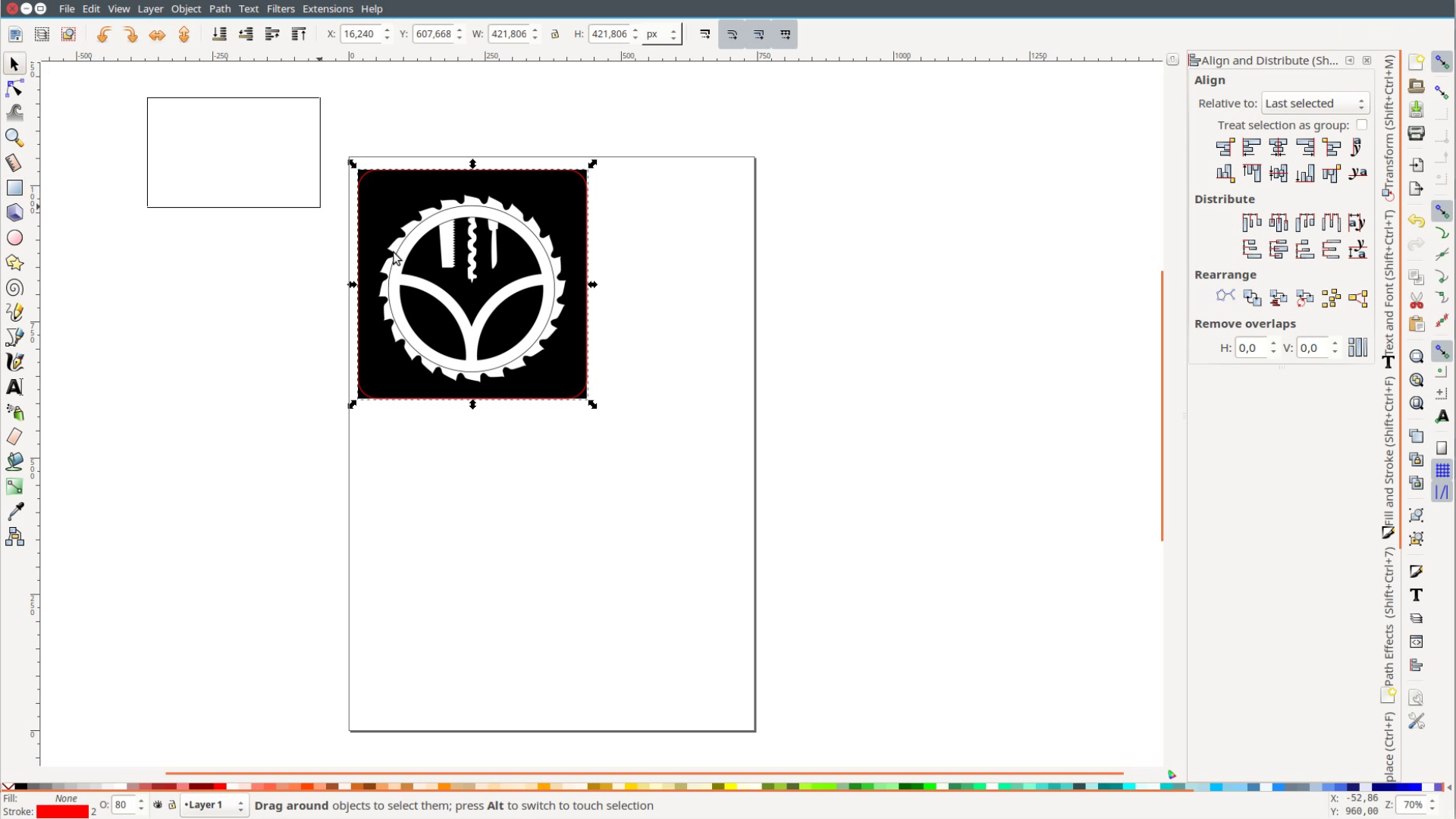
For a better look we can round over the corners a bit by grabbing and dragging the upper right circle. If you want a specific size select both objects and put the size in these boxes on the top. Lastly save the file and are done.
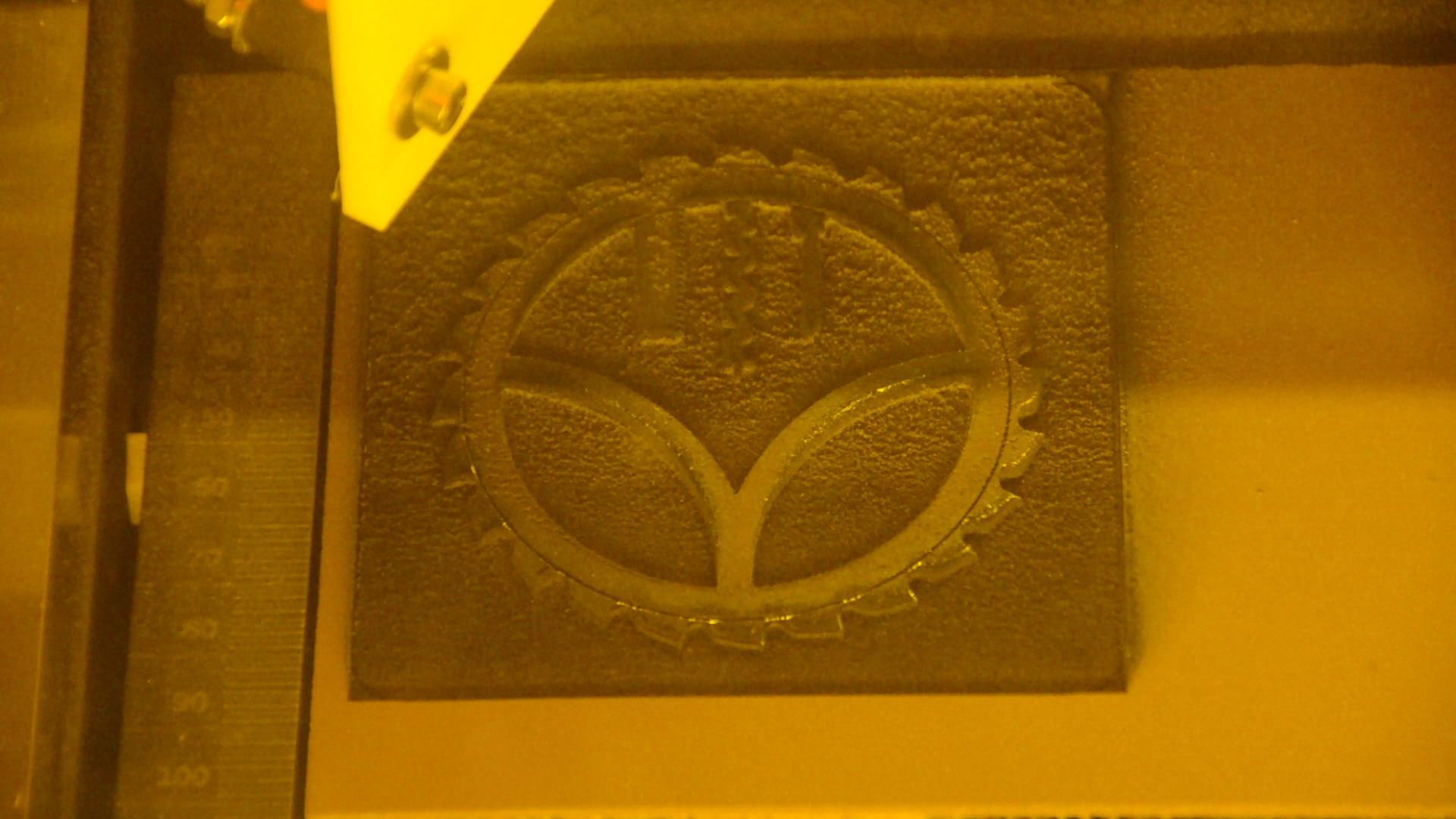
We will cut the stamp from linoleum which cuts nicely on the laser cutter and doesn’t produce toxic fumes. Let’s open the K40 whisperer software and cut the design.
First initialize the laser by pressing the button. Second load the design file.

Thirdly set the laser power to 12, the speed in the black box to 100 and hit the raster engrave button.
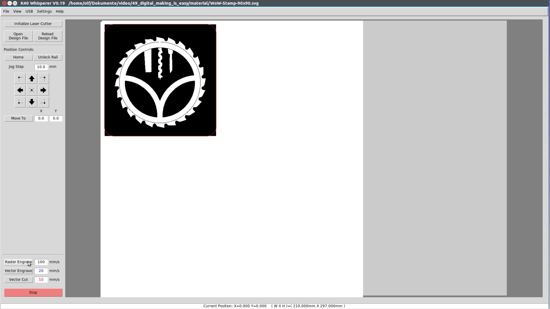
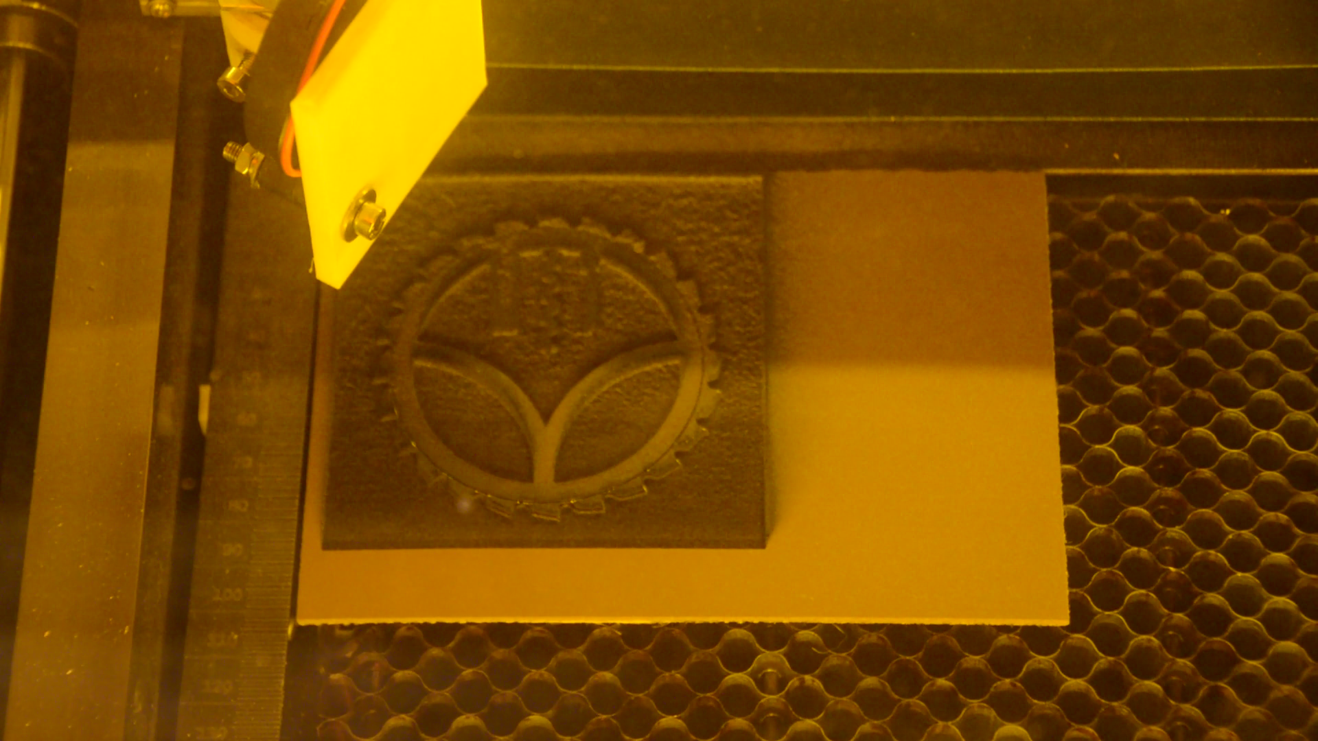
The laser will now engrave the graphic.
Lastly change the speed in the red box to 10 and the power to 25, hit the Vector cut button and we are done with the laser.
The mounting plate on the CNC
Next let’s create the mounting plate for the stamp. We will do that in the open source software FreeCAD. We have a recent article on why we use FreeCAD rather than Fusion 360.
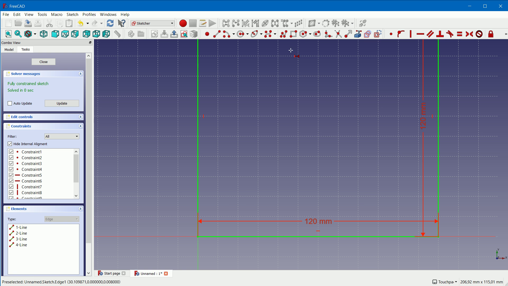
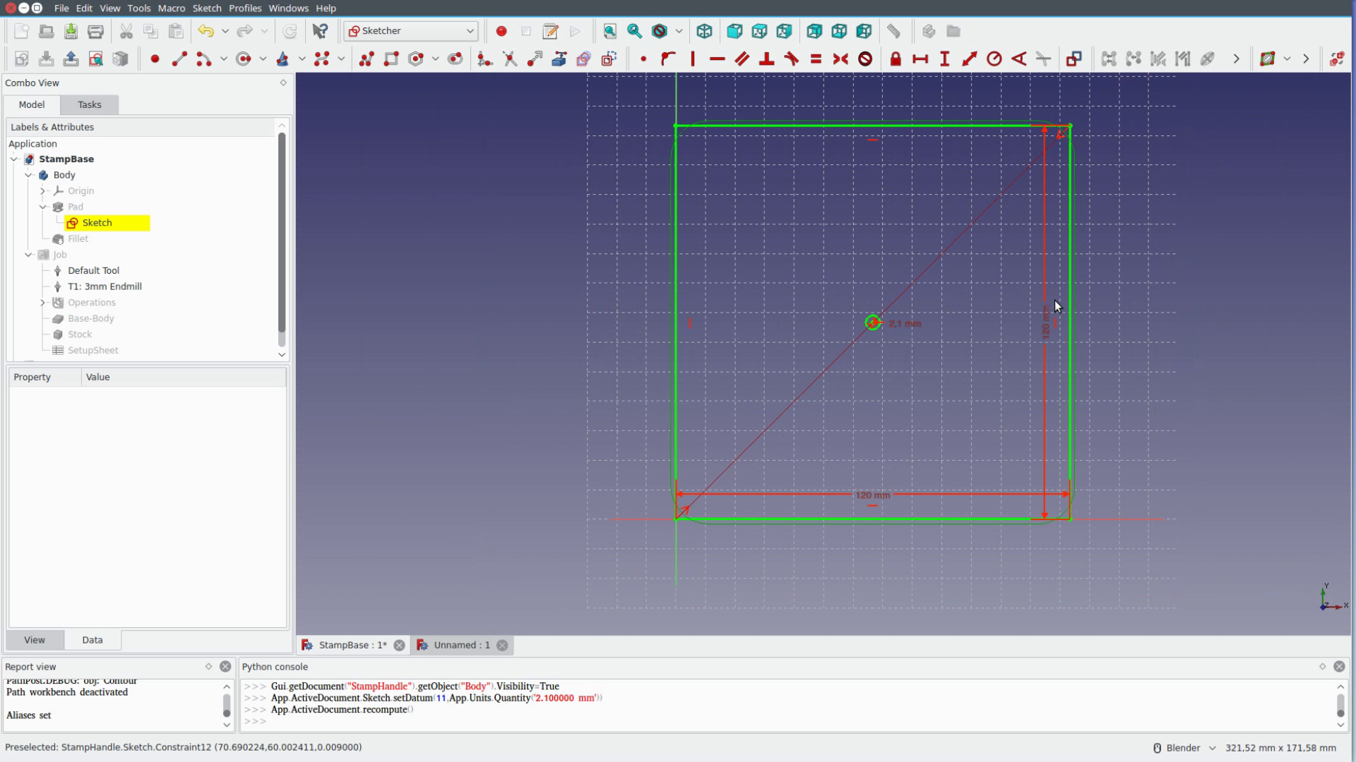
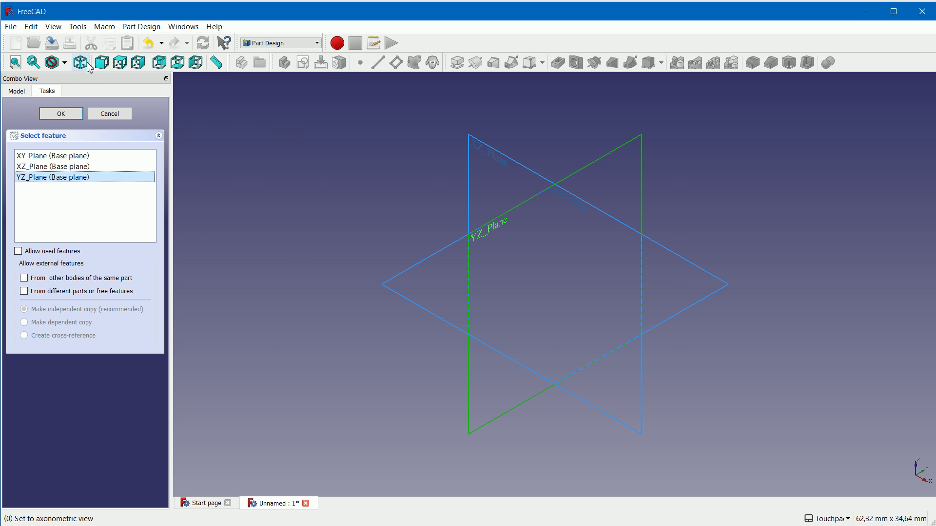
In FreeCAD we select the Part design workbench in this box. First click on tasks to create a new body and a new sketch in the XY plane. For the second step hover over the point in the middle and draw a rectangle.
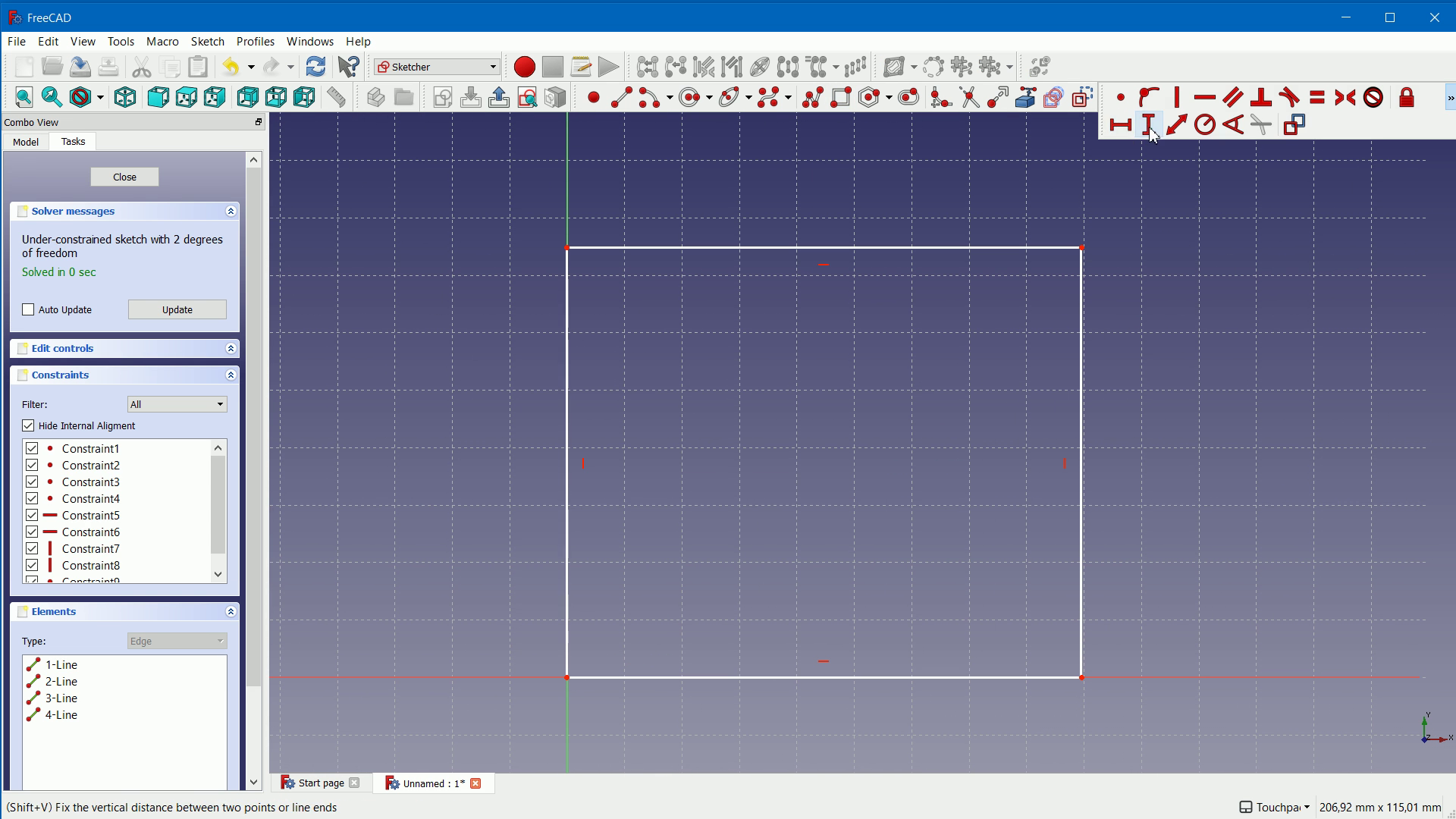
The rectangle gets a horizontal measurement and a vertical measurement that is identical to the size of the rectangle in Inkscape.
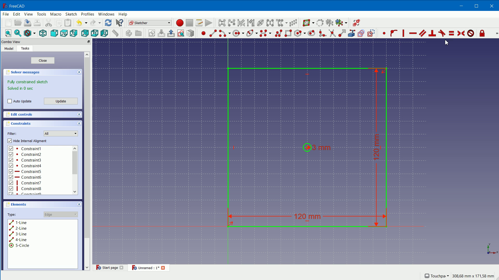
Thirdly we create a circle. With this tool we click on the circle and give it a 2 mm radius. To position the circle click on two corners of the rectangle, then on the center of the circle and press this button to center it.
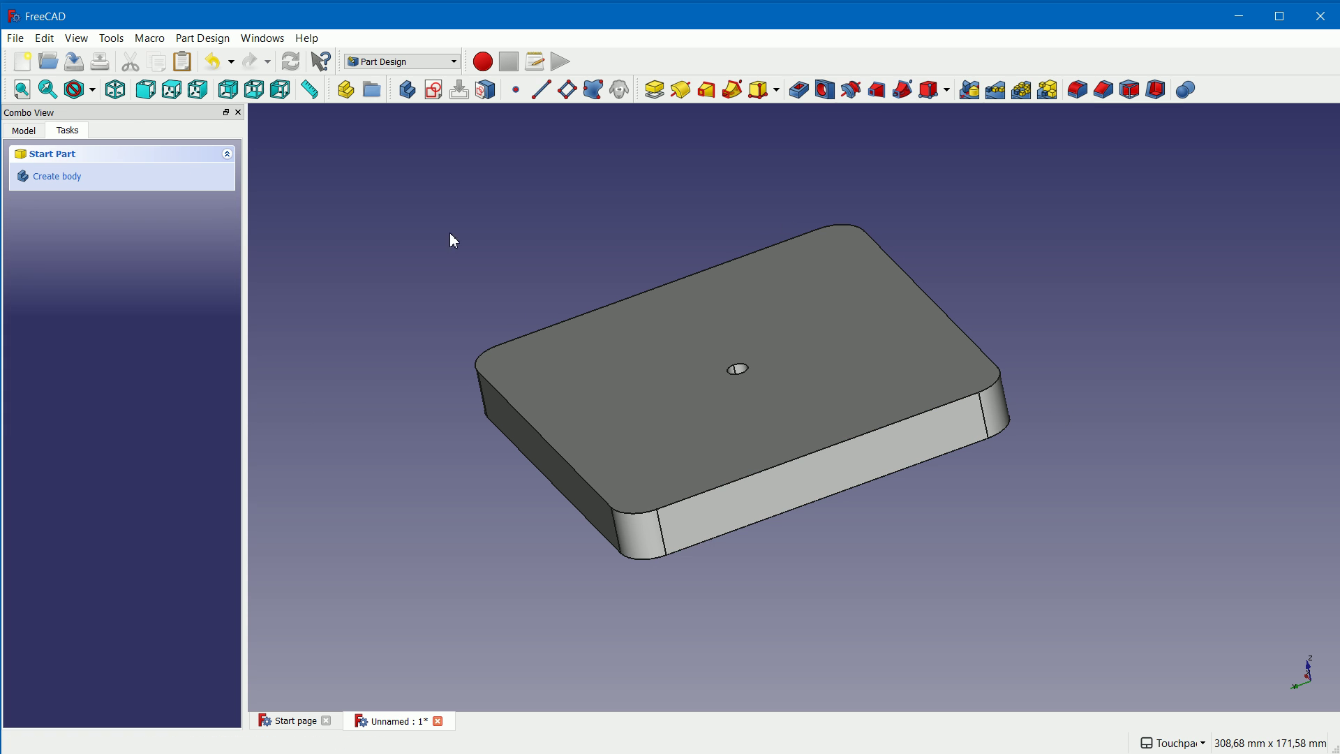
From this sketch we now create a body. We close the sketch, click on pad and input the width of our material. Lastly we select the edges at the four corners and click the fillet tool in order to round over the corners.
Did you realized that we used the wrong number for the circle diameter? Let’ quickly fix this by going back and changing the parameter.

Generating the g-code
We now have created the shape but still need to convert it into a program that we can feed to the CNC machine.
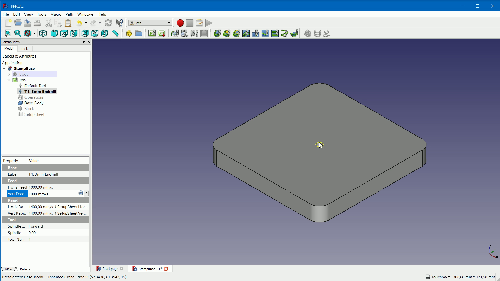
For that we go to the Path workbench of FreeCAD. Create a new path object and change a few things compared to the default.
We do not have any extra stock on the top or the bottom and we choose grbl as the output format. We then create a new tool with 3mm diameter and 20 mm cutting length and change it’s cutting speed to 1000 mm/min and let it plunge only 1.5 mm at a time. Between cuts the CNC can move with 1400 mm/min. These setting might seem complex but you only have to do them once.
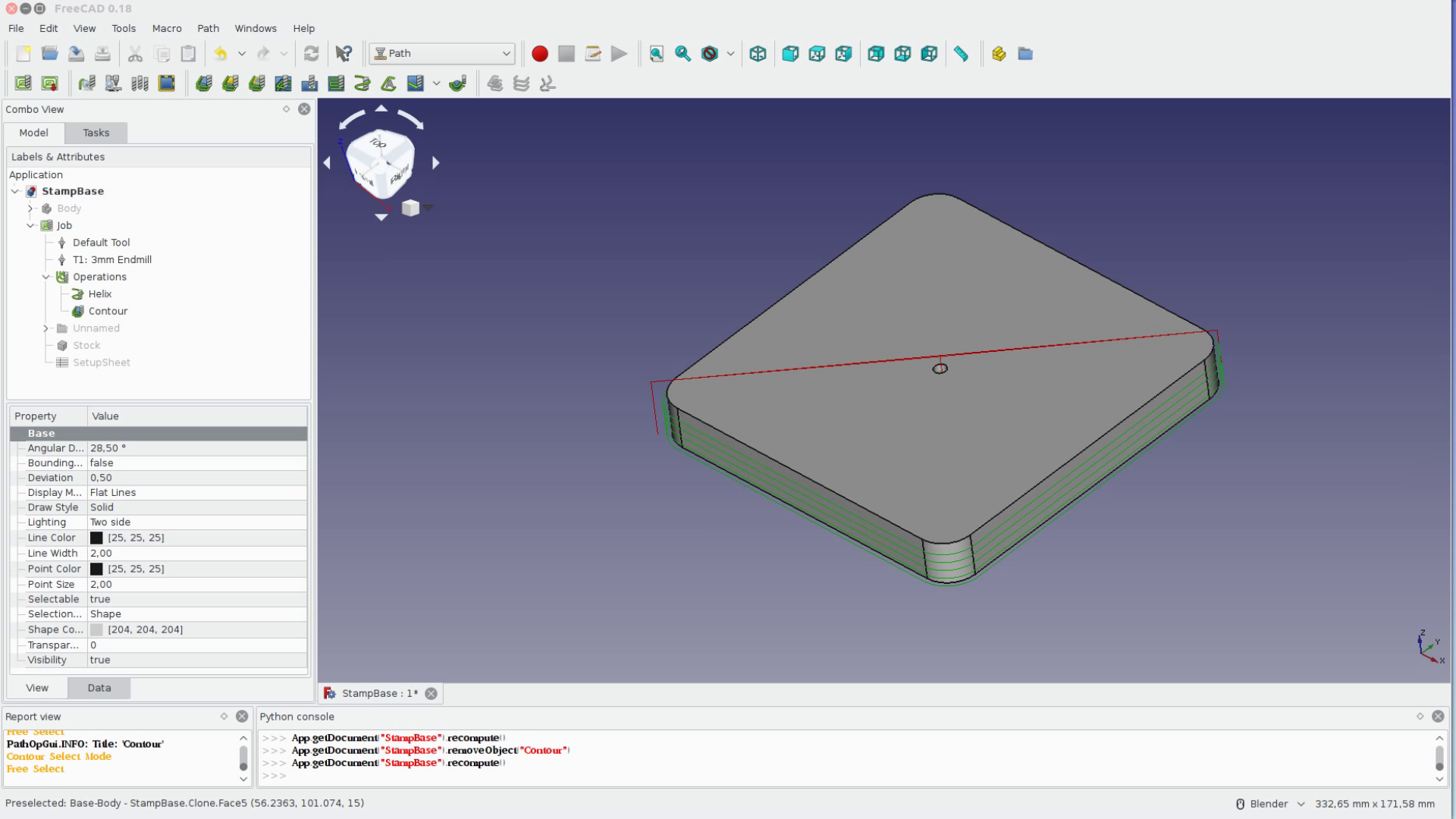
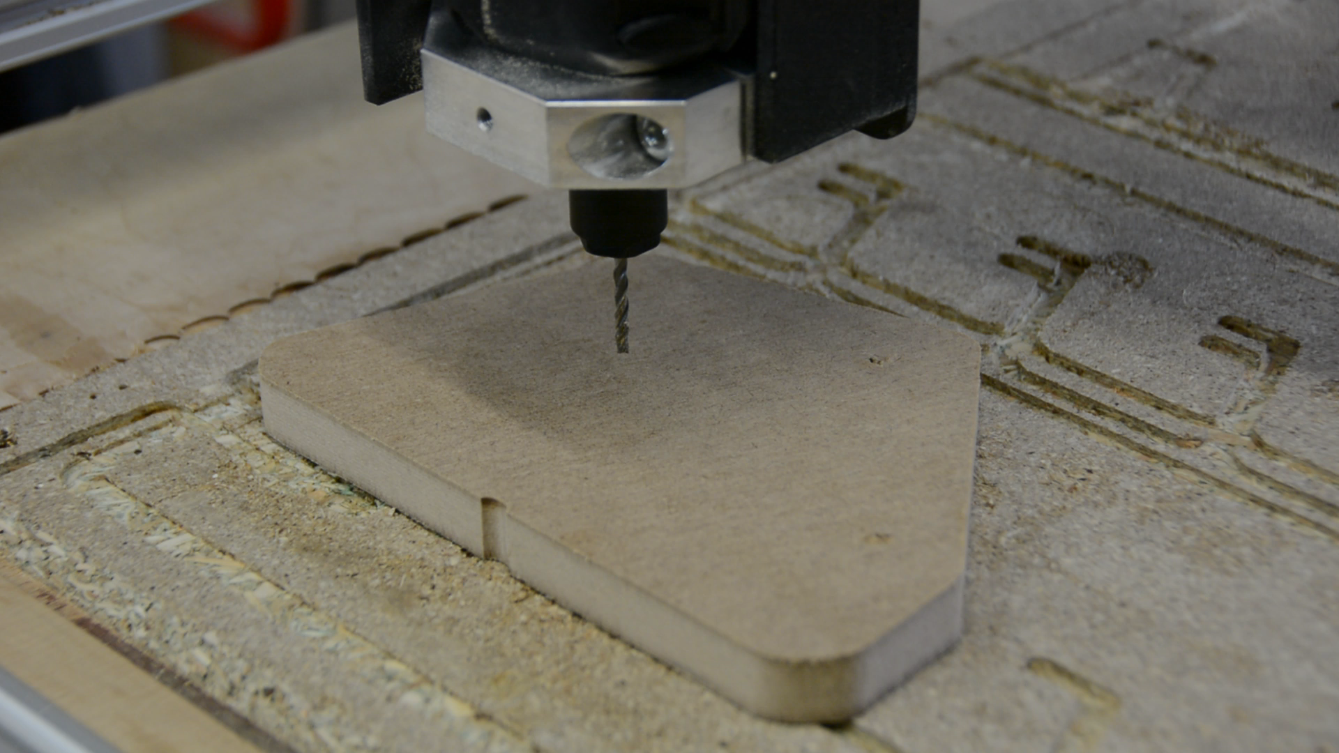
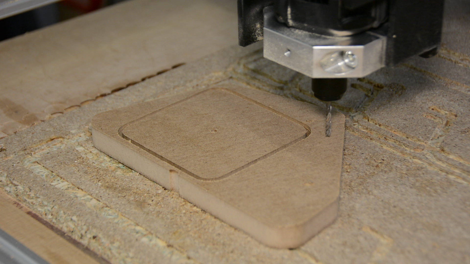
Creating the actual gcode program is fairly simple. We first select the underside edge of the hole in the middle and create a helical path. We then click on the contour button and save the gcode file.
On the CNC we hot glue a scrap piece of MDF to the bed of the machine.
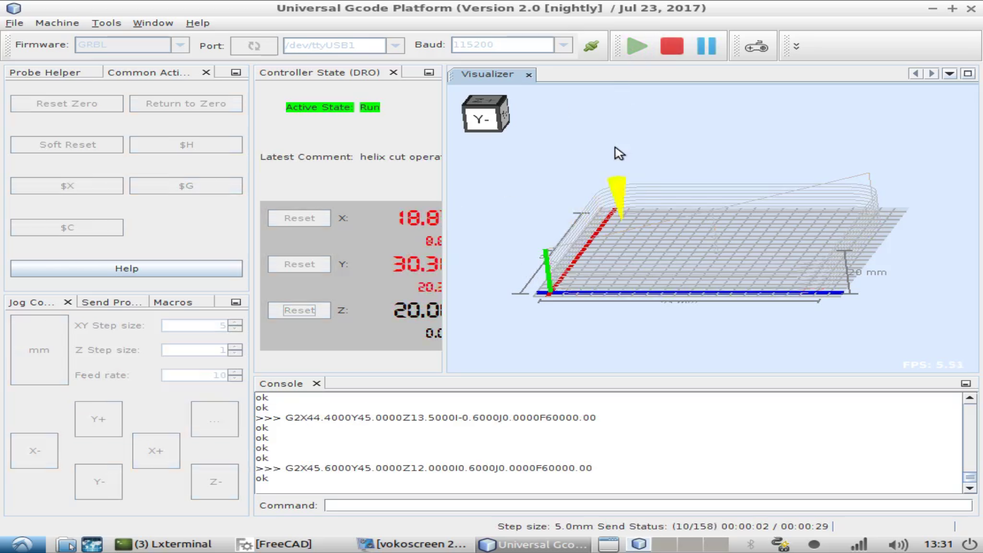
The software to send the gcode to the CNC is called Universal Gcode Sender.

We don’t have to be very precise for this task so we just manually move the endmill over the wood to zero the X and Y and to the bed to zero the Z axis.
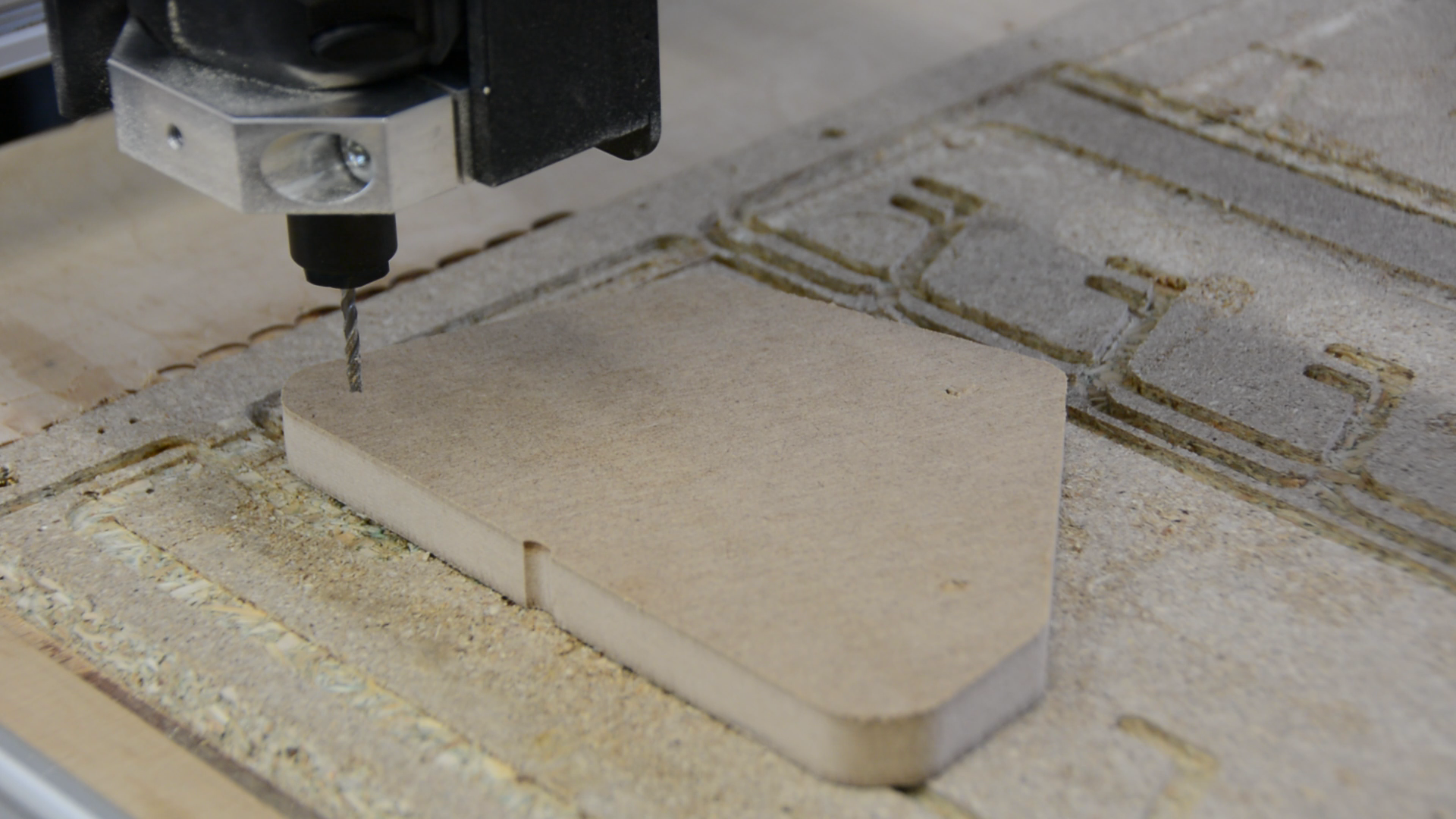

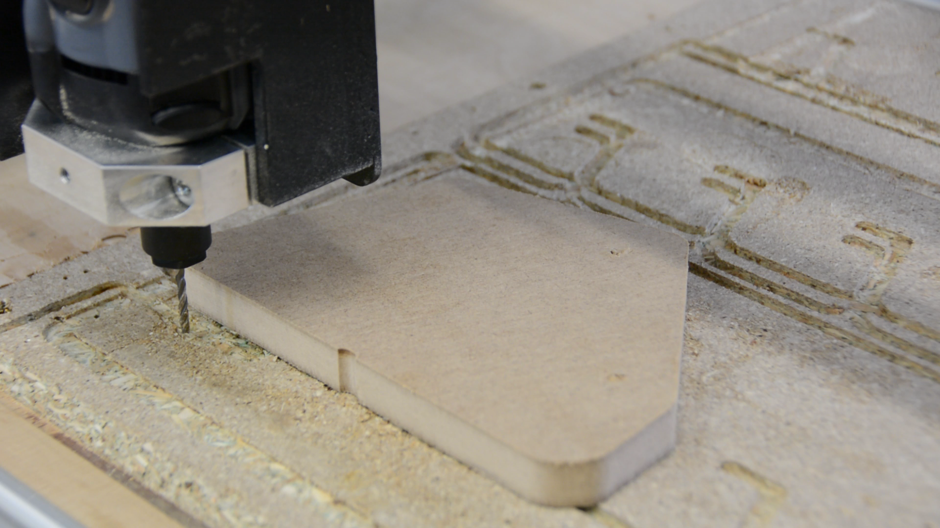

Now we open the file, press the play button and watch the machine doing its thing.
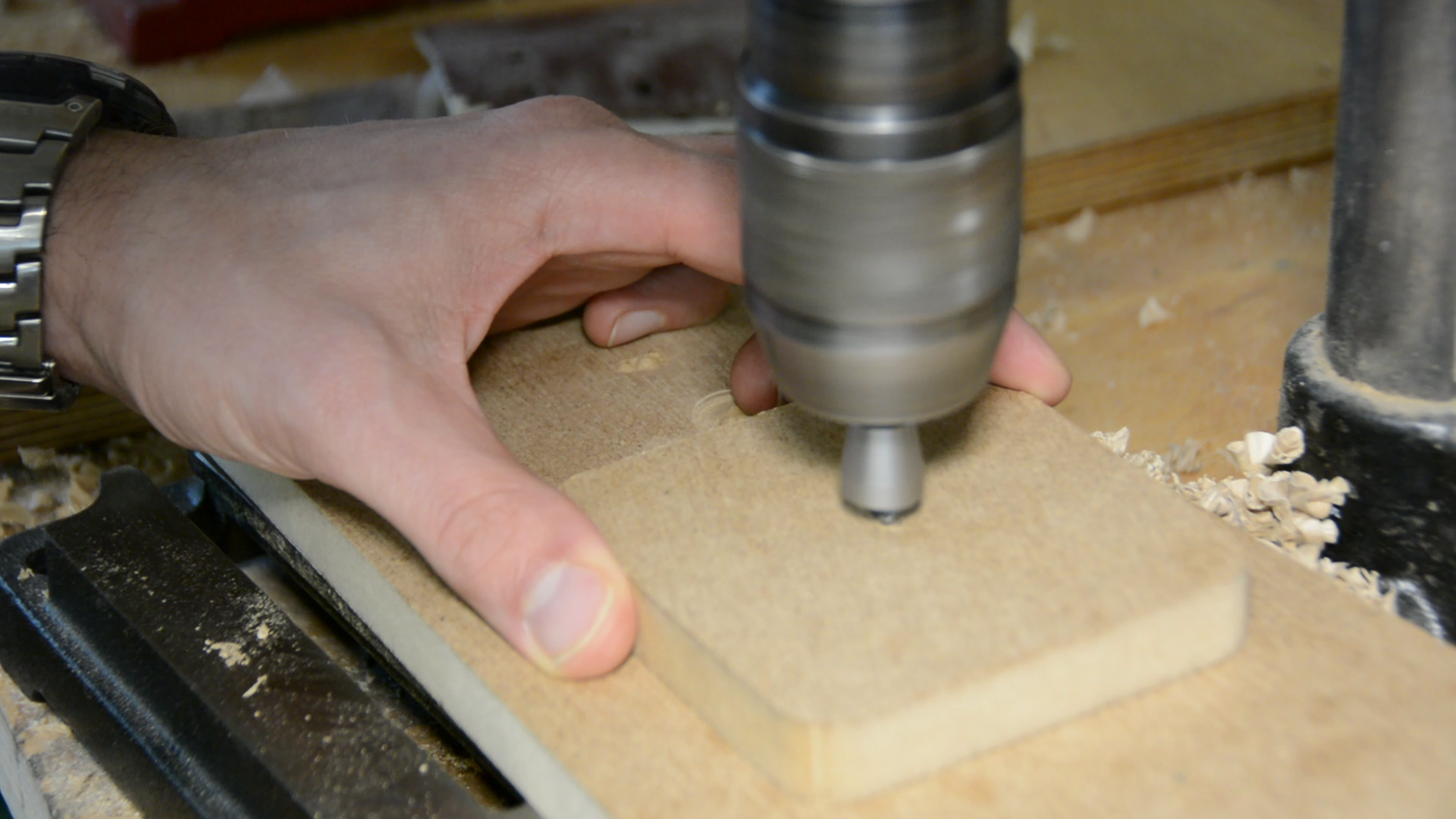
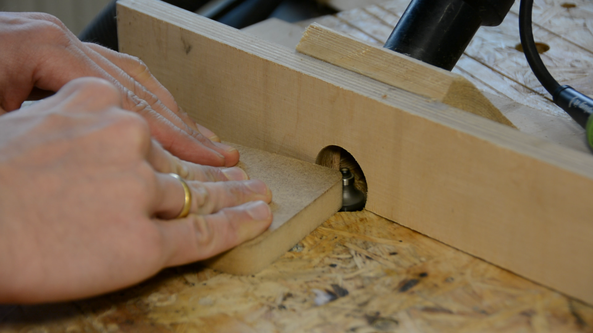
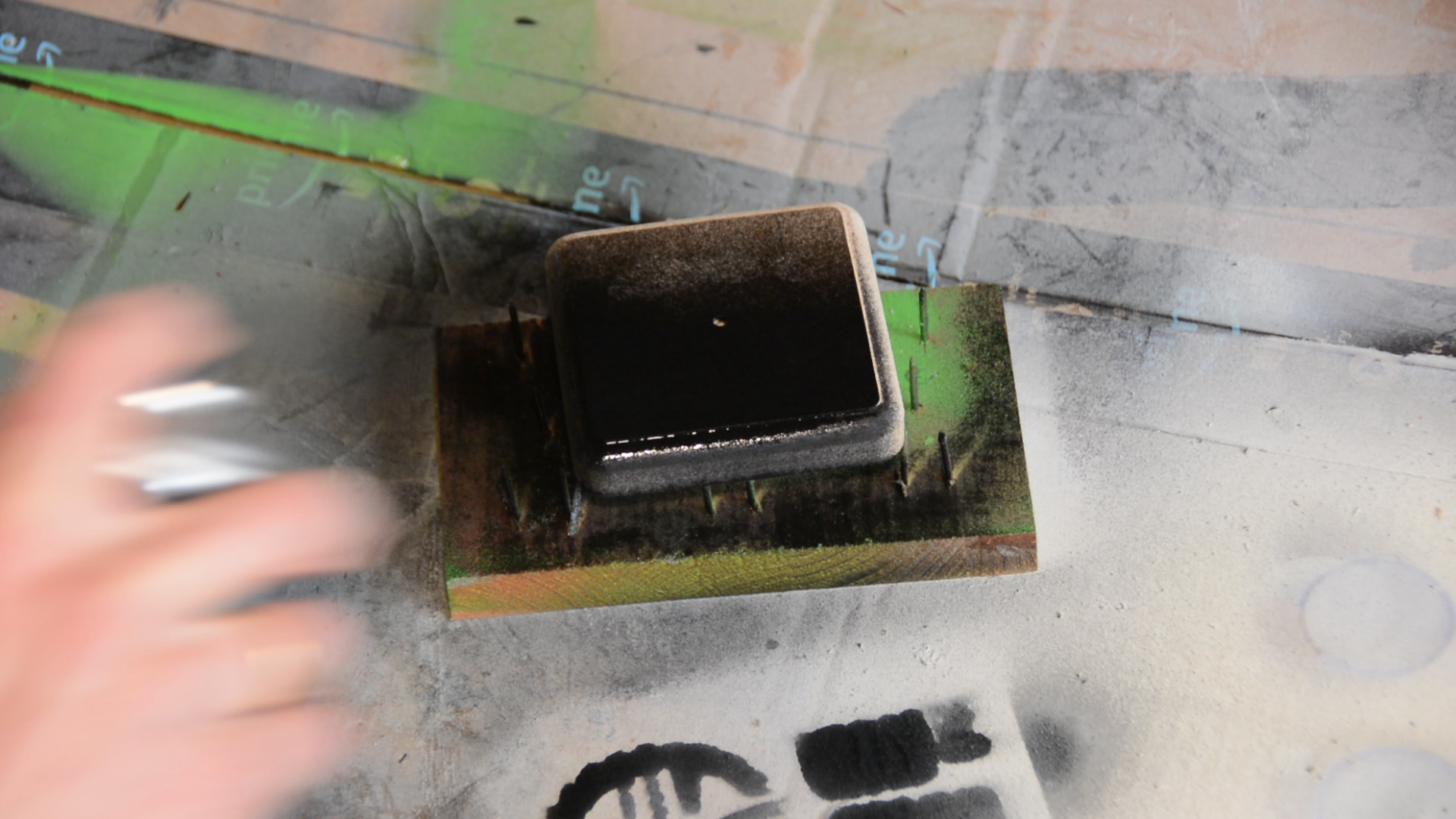
Before moving on with the handle we counter bore the hole, round over the edges and paint the MDF black.
3d printing the handle
For the handle we go back to FreeCAD and open the part design workbench again.
As last time we create a new body and a sketch – just this time in the YZ plane. In the sketch we draw a straight vertical line, then a small step, and a horizontal line.
On the top we put a circle and connect the circle with a curve to the horizontal line at the base. We only have to put one measurement in this sketch: the small step has to be 2 mm wide.
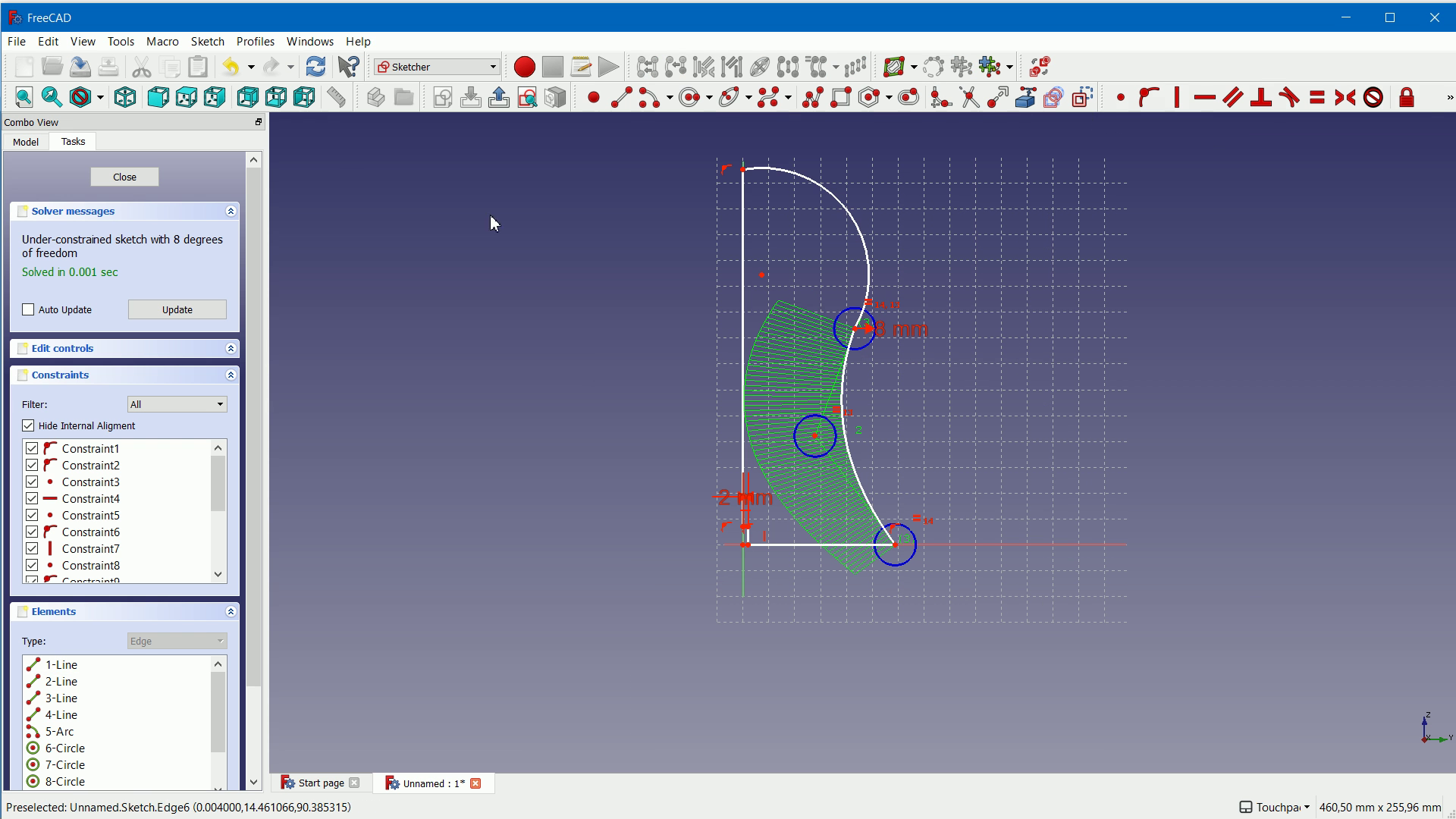
The remaining part should just look nice and roughly fit the MDF plate – so move the dots around till it looks good to you.

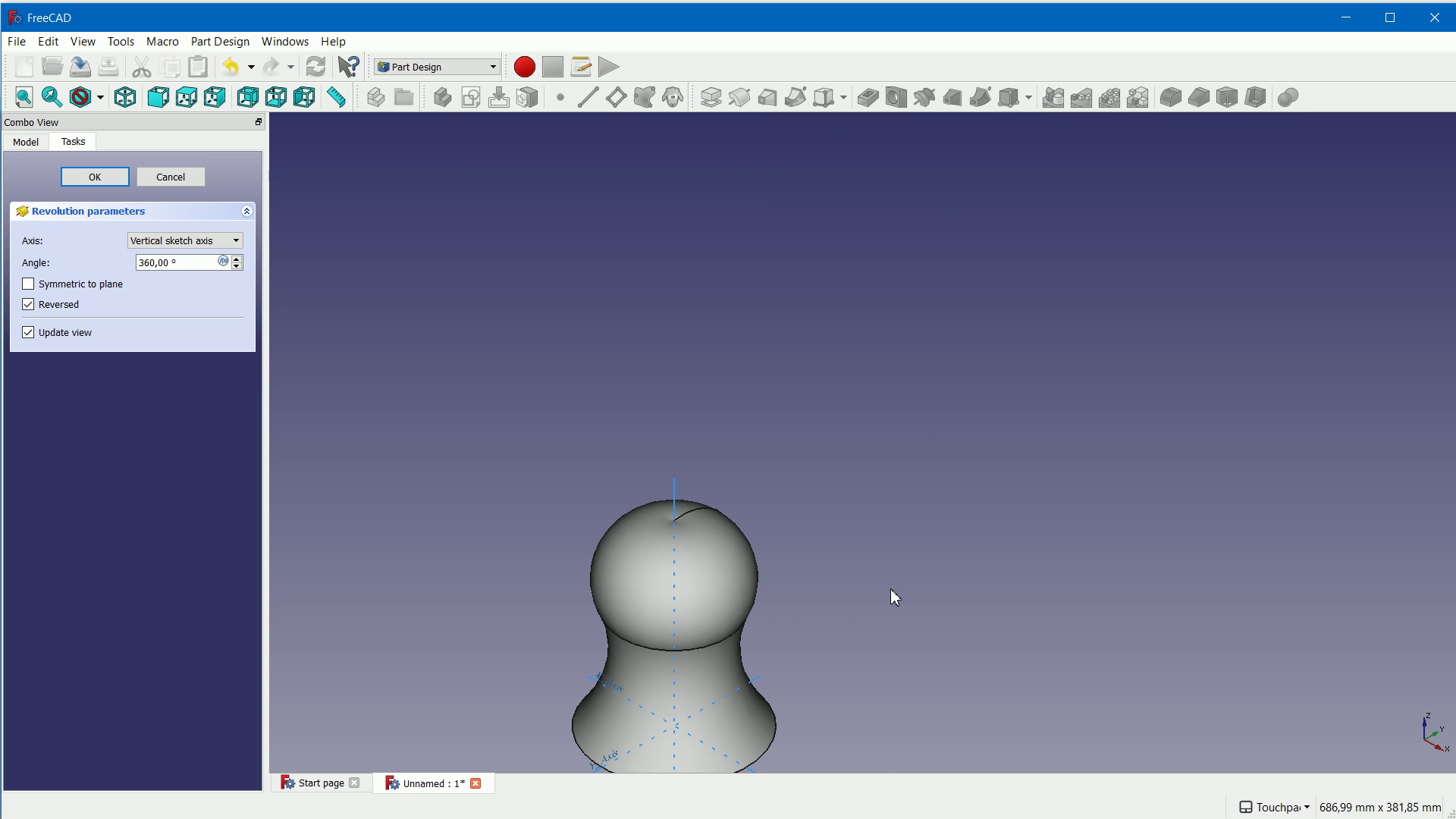
After closing the sketch click on revolve and the handle is done. We select file export and save the file as an STL file.
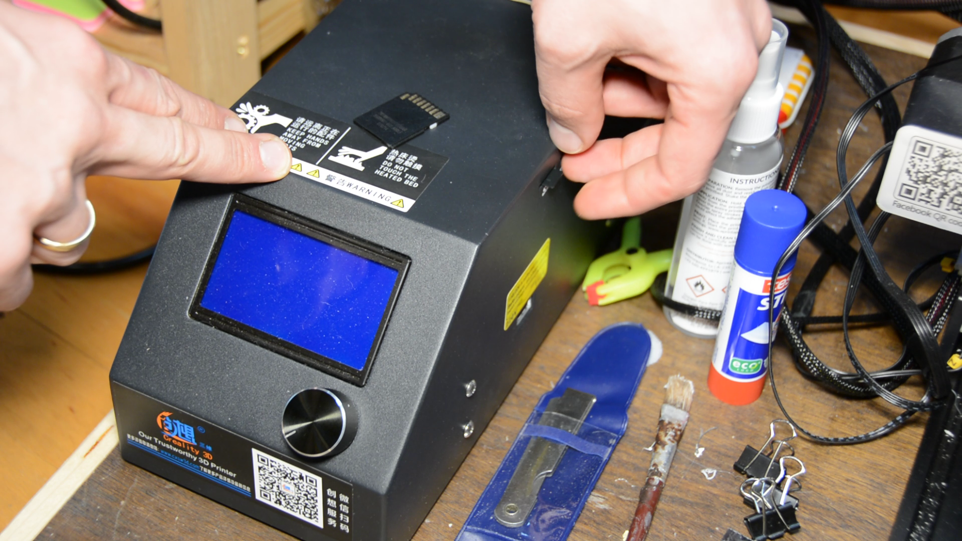
This file is now opened in a slicer such as Cura and saved on a SD card.
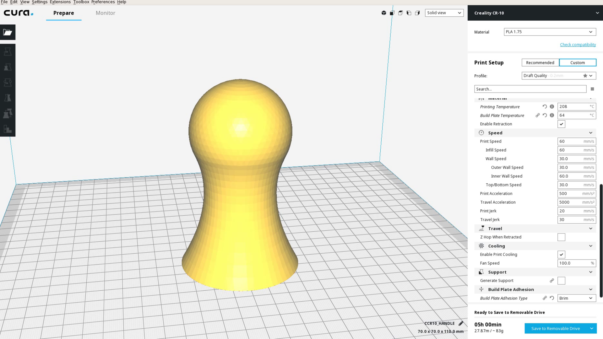
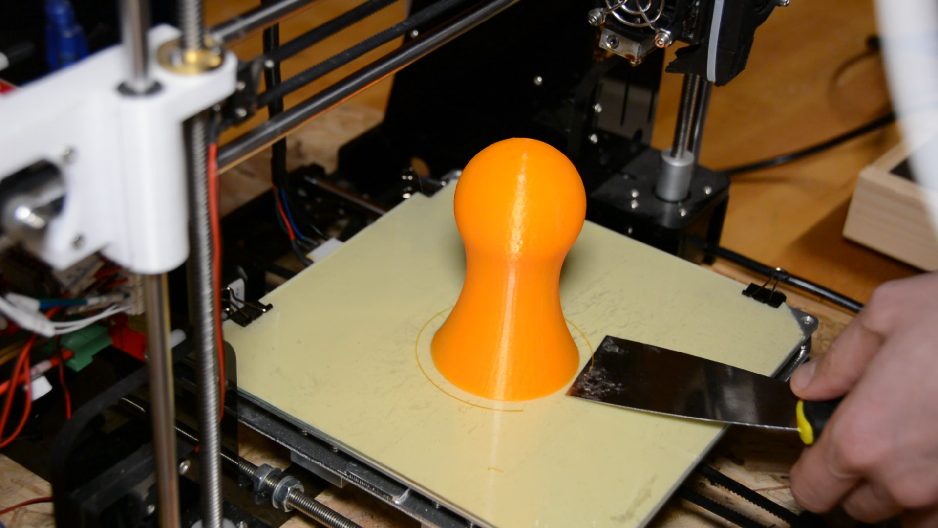
We put the SD card in the printer, select the file and watch it printing.
Asssembly
Finally we can assemble the three parts.
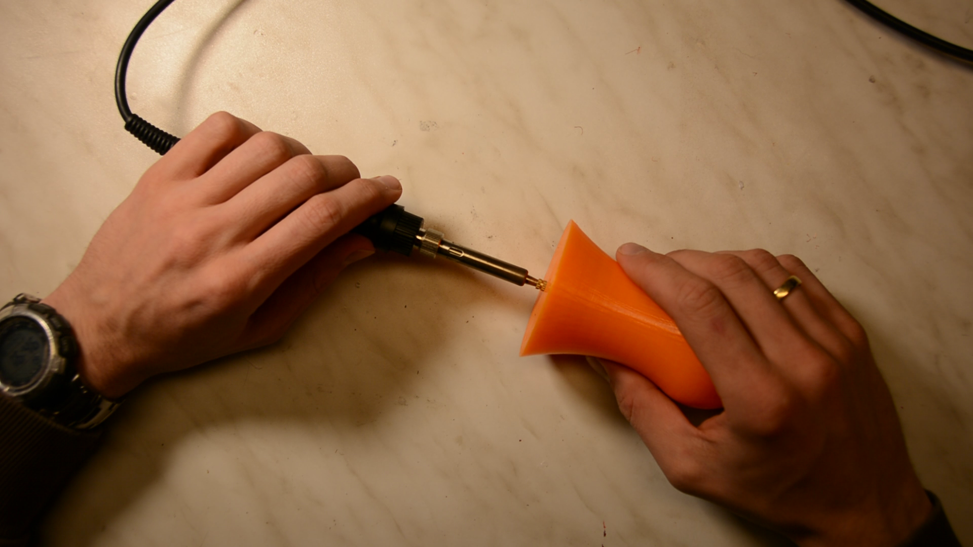
With a soldering iron we press a metal thread insert in the handle.
We then screw the handle to the base and glue the stamp to the base with contact cement.
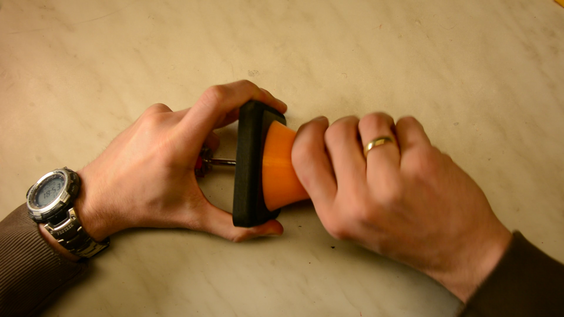
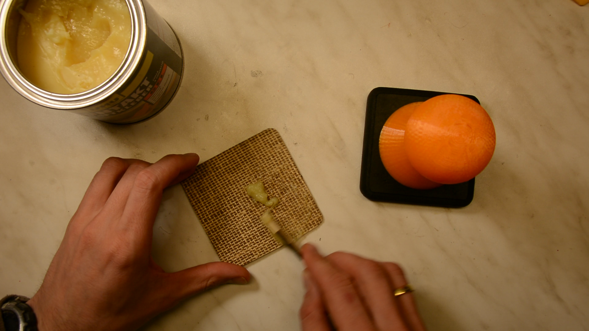
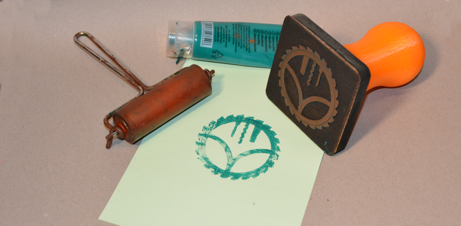
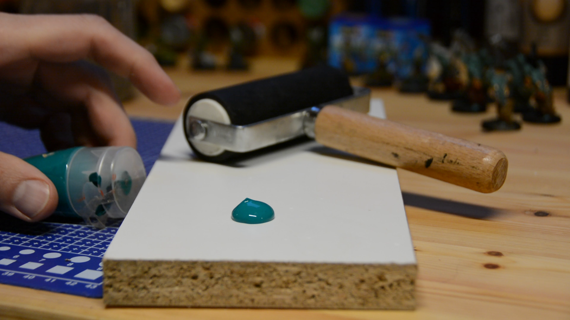
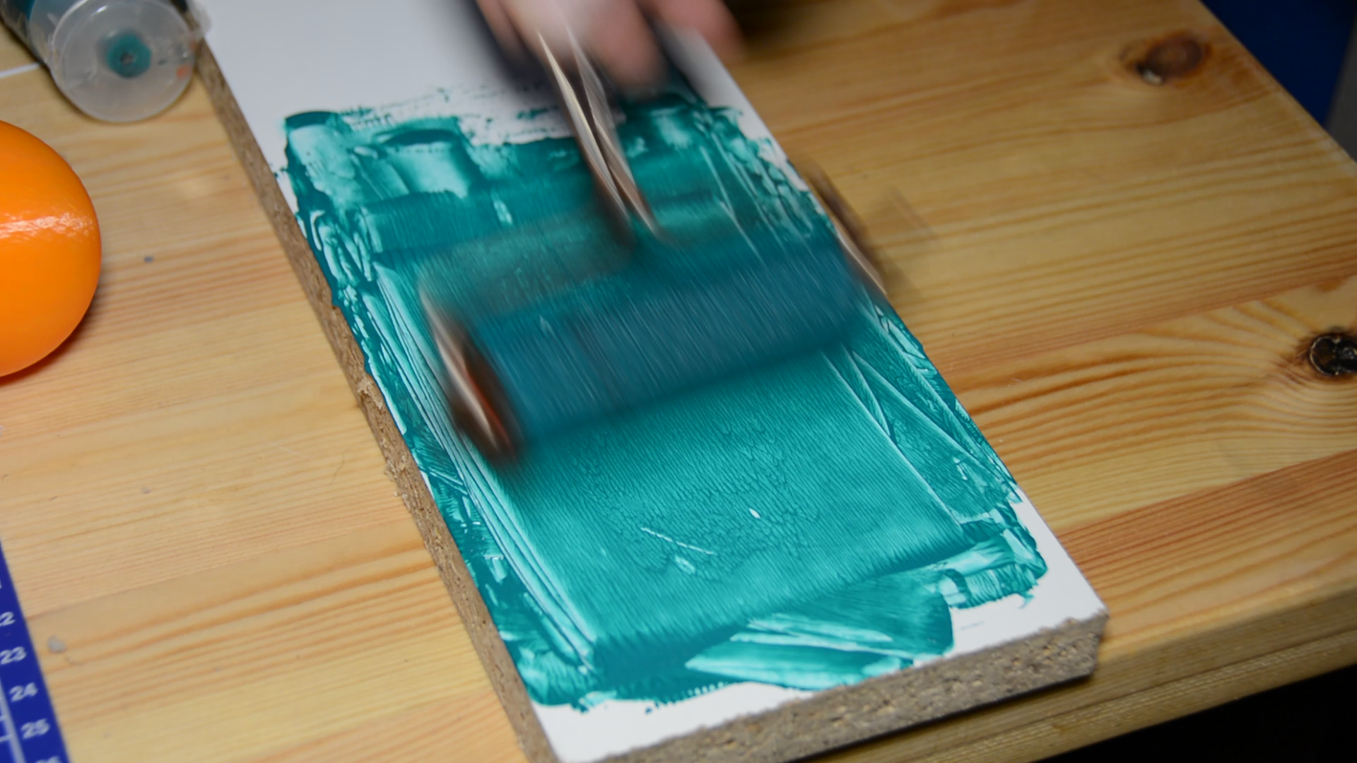
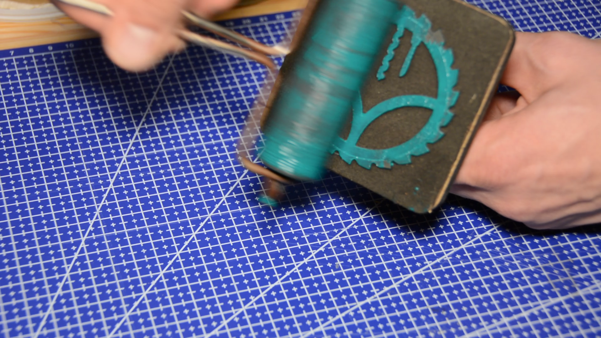
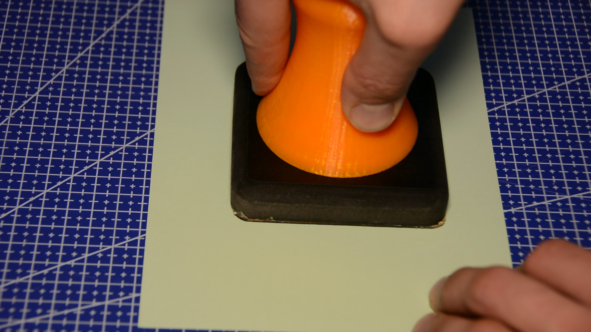
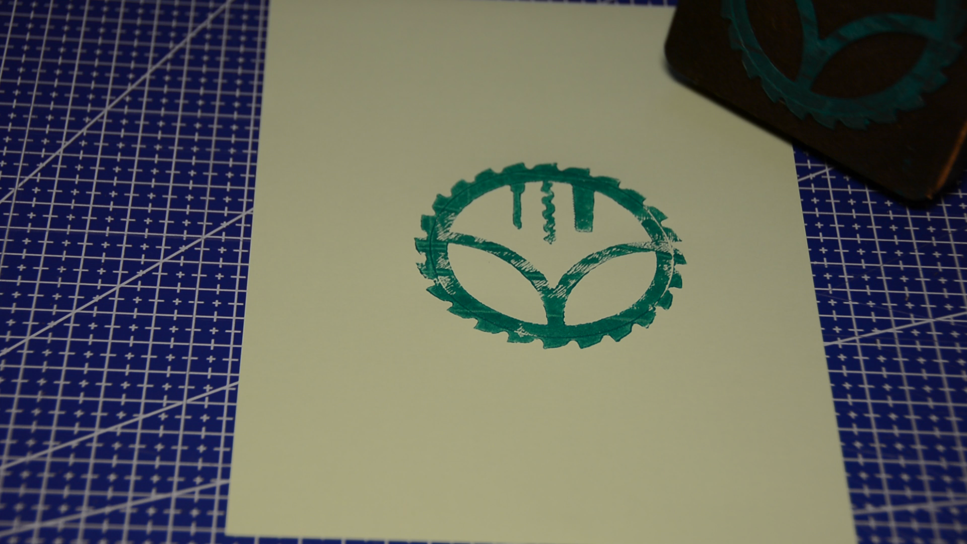
We can now use the stamp and test it out.
Hopefully this article inspired you to make something with digital tools.