In this article we build a picture frame hanger to hang pictures on a sloping wall. We create the design with FreeCAD and a laser cutter but will also show a low tech solution.
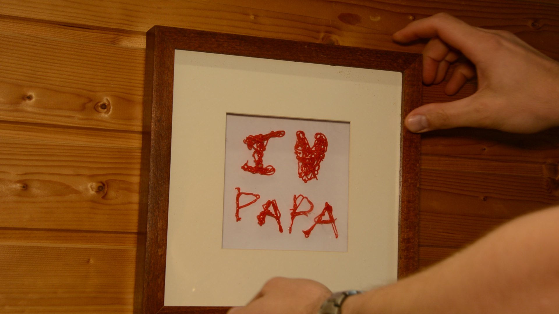
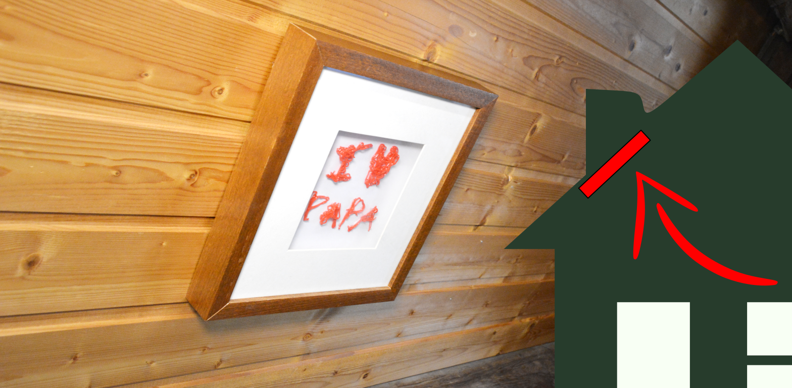
Our kids are making beautiful art pieces and I would love to hang them in my office room. Unfortunately this room is under the roof so the walls are sloped and it’s difficult to hang pictures.

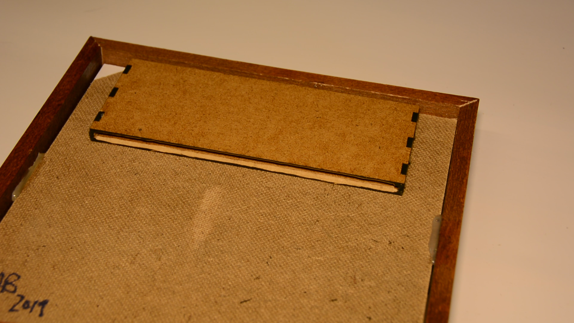
We design the hangers in FreeCAD and cut them on the laser cutter but at the same time we will also show an alternative method to make them with hand tools. We first have to create a box that fits into the backside of the frame and a second part that will be mounted to the wall and then slips into that box.
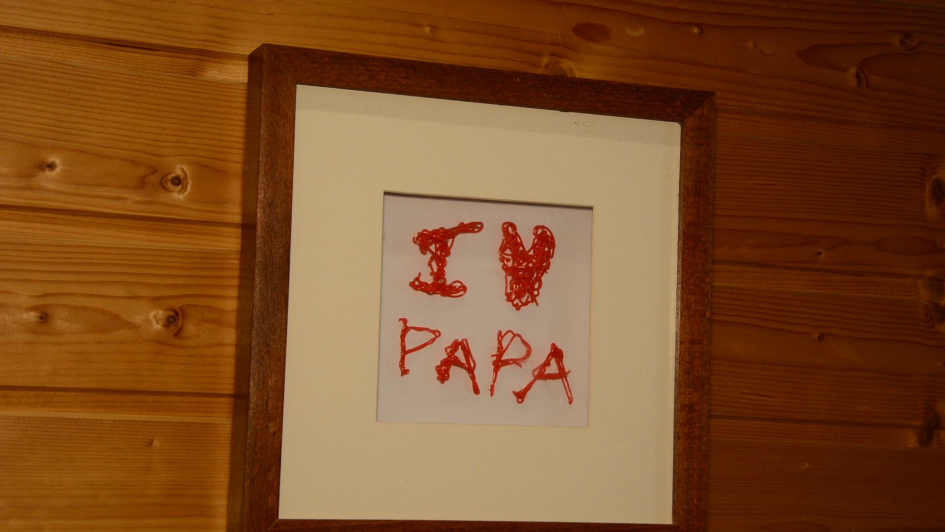
While my son created this piece with his 3D pen my daughter painted a picture. Looking at the backside of the two frames we can see that the depth on the backside is different.
This calls for a parametric design so that we have to develop our CAD model only once and can output the shapes with different measurements.
Design in FreeCAD
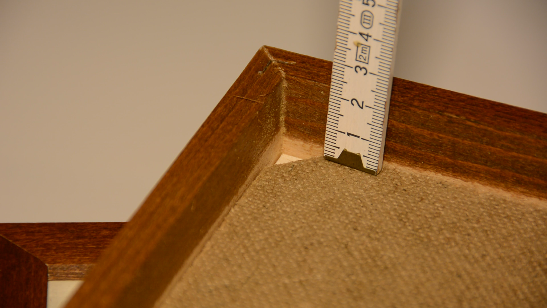
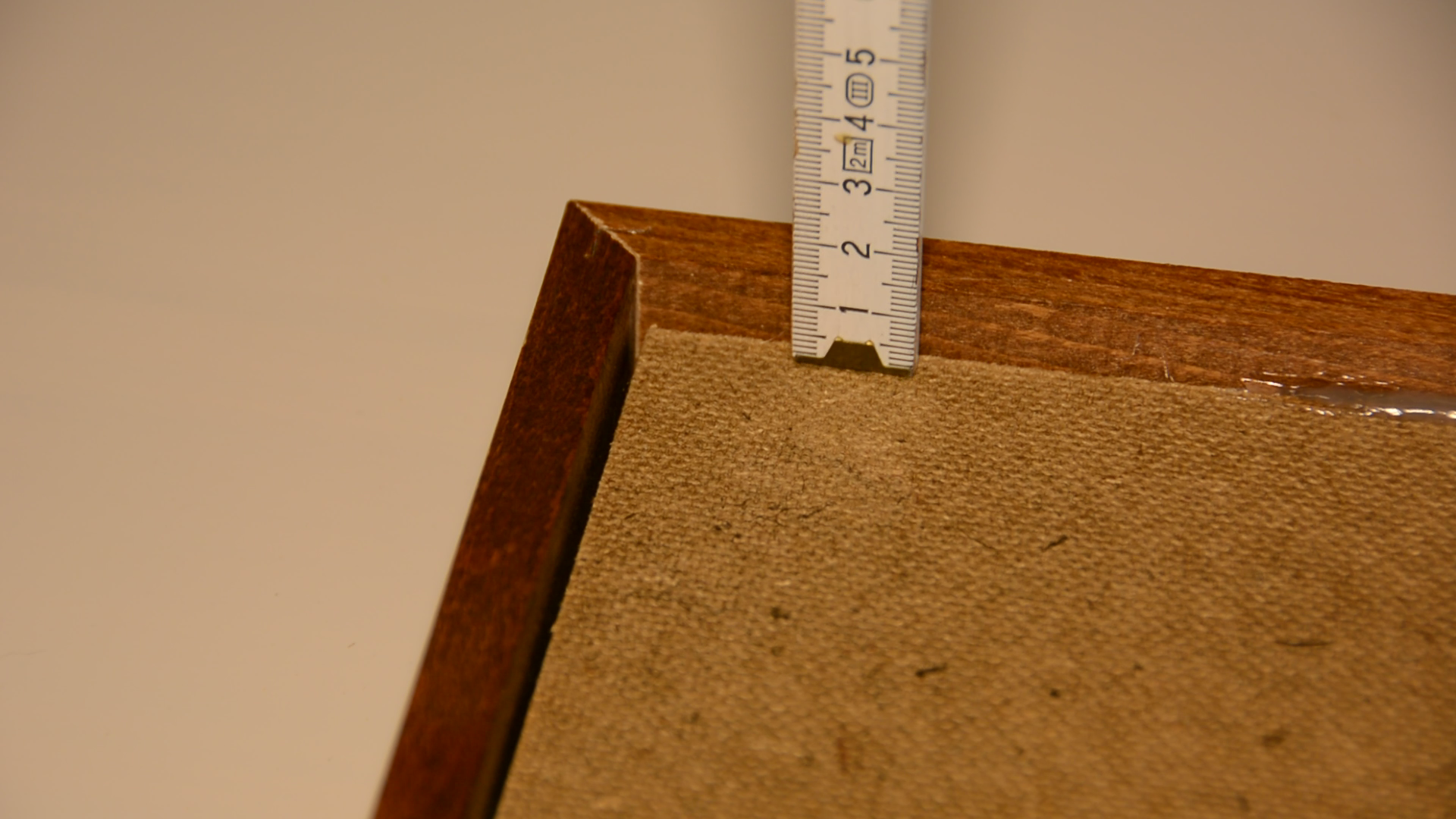
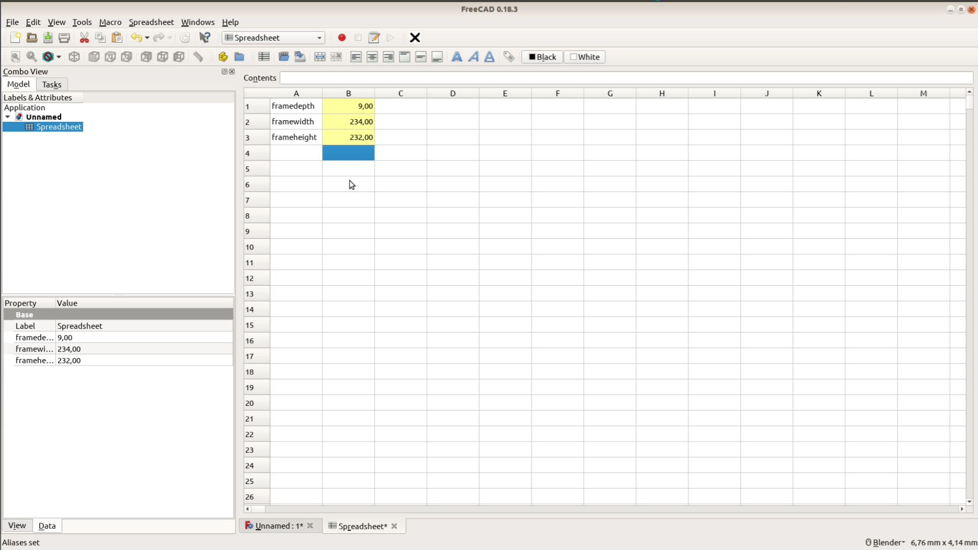
A spreadsheet is the easiest way to create parameters in FreeCAD. We name our dimensions in the first row and add their values in row B. The parameters we need are the depth, width and height of the available space at the backside of the frame.
If you want to create the hanger with hand tools and don’t want to mess around with CAD you can download a spreadsheet which does the same calculation here.
In FreeCAD we use a macro to automatically copy the values of the spreadsheet in variables we can use later in the design.
A description of the macro can be found at the following URL: https://www.freecadweb.org/wiki/Macro_Alias_Manager. You can either download the macro from this link and install it manually or you just open FreeCAD and select Tools > Addon Manager > Macros and install the “Alias Manager” Macro from there.
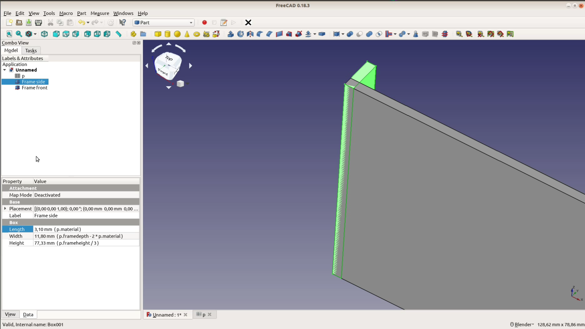
In the part workbench in FreeCAD we add a simple cube. This cube is the shorter side of our box. As everything will be cut from 3mm MDF one dimension is the material thickness, which
we add to the spreadsheet.

The height of the box is a third of the frame’s inner height and the last dimension corresponds to the depth of the frame minus two times the material thickness.
We add the long side with the same height and material thickness and a width that is 80% of the frame’s inner width.
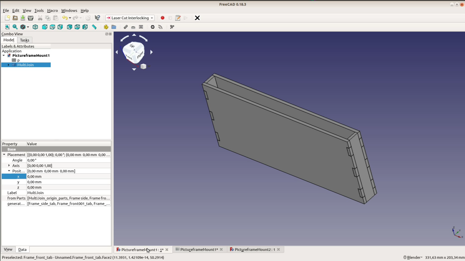
With the clone function from the Draft workbench we duplicate the short and the long side and position them to form a box by adding the values in the placement tab.

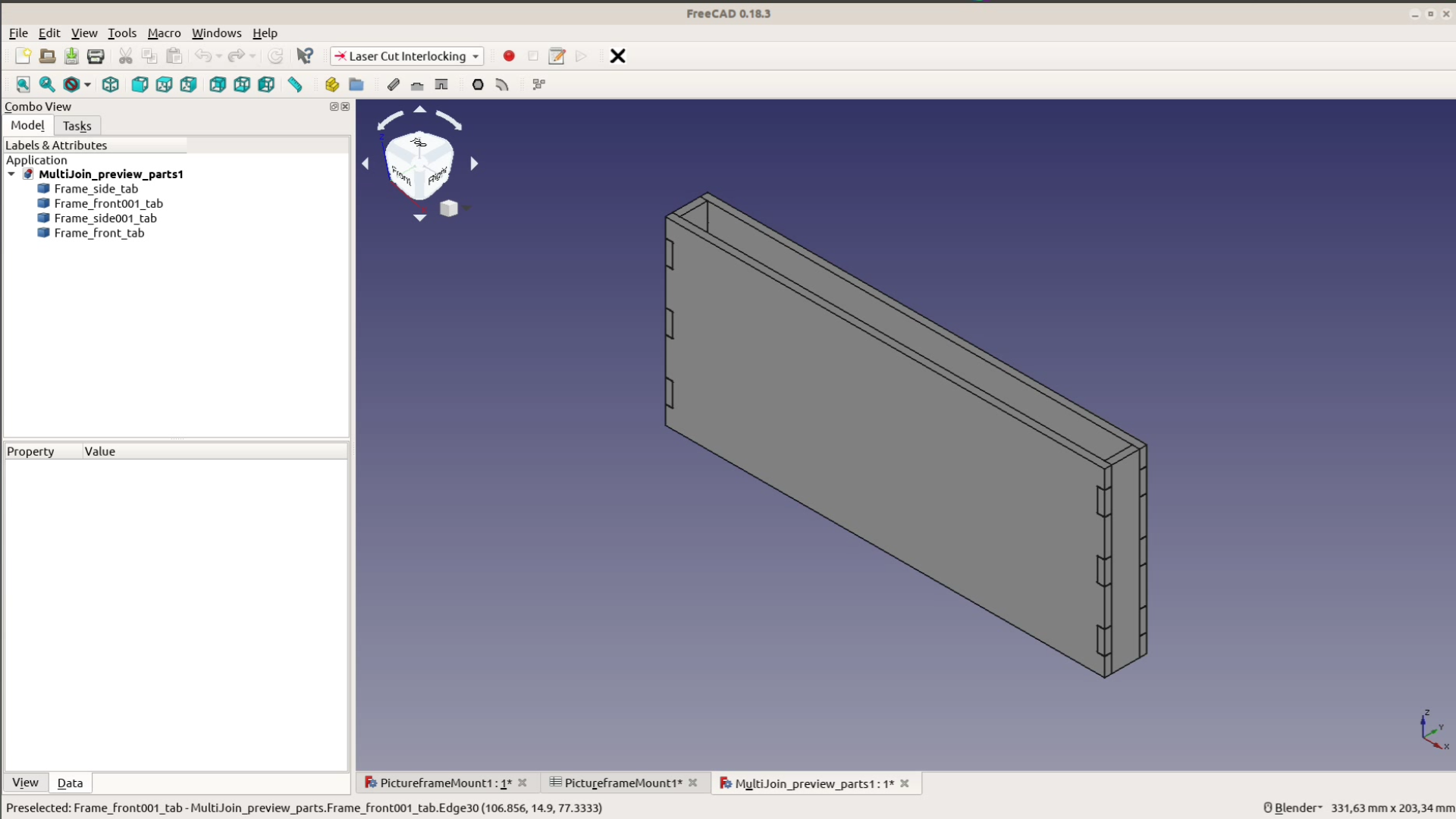
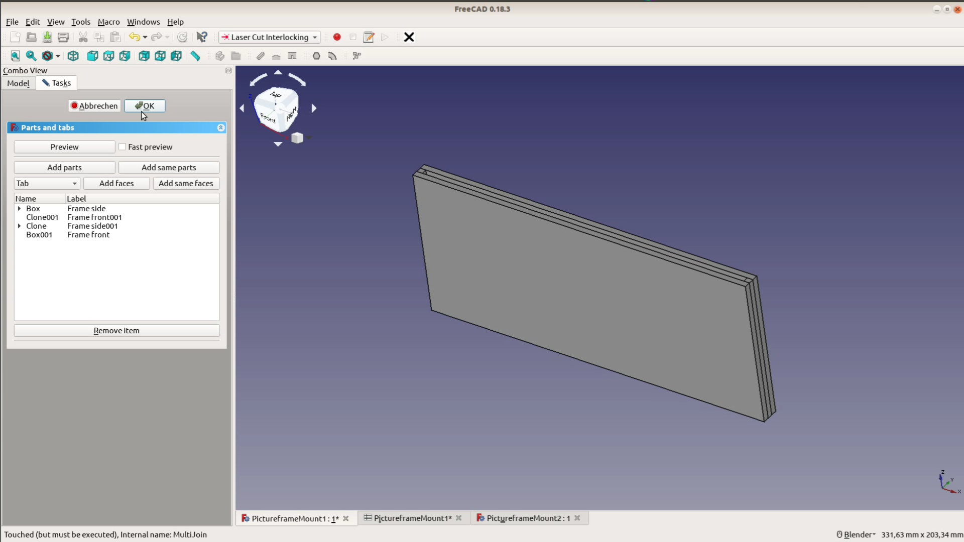
With the laser cut interlocking workbench (we have a separate article only on this workbench) we create finger joints at each corner. We add all the parts to a tab connection and then mark the faces of the short pieces to receive 3 tabs of 10 mm each.
Sloping wall picture hanger – then manual way
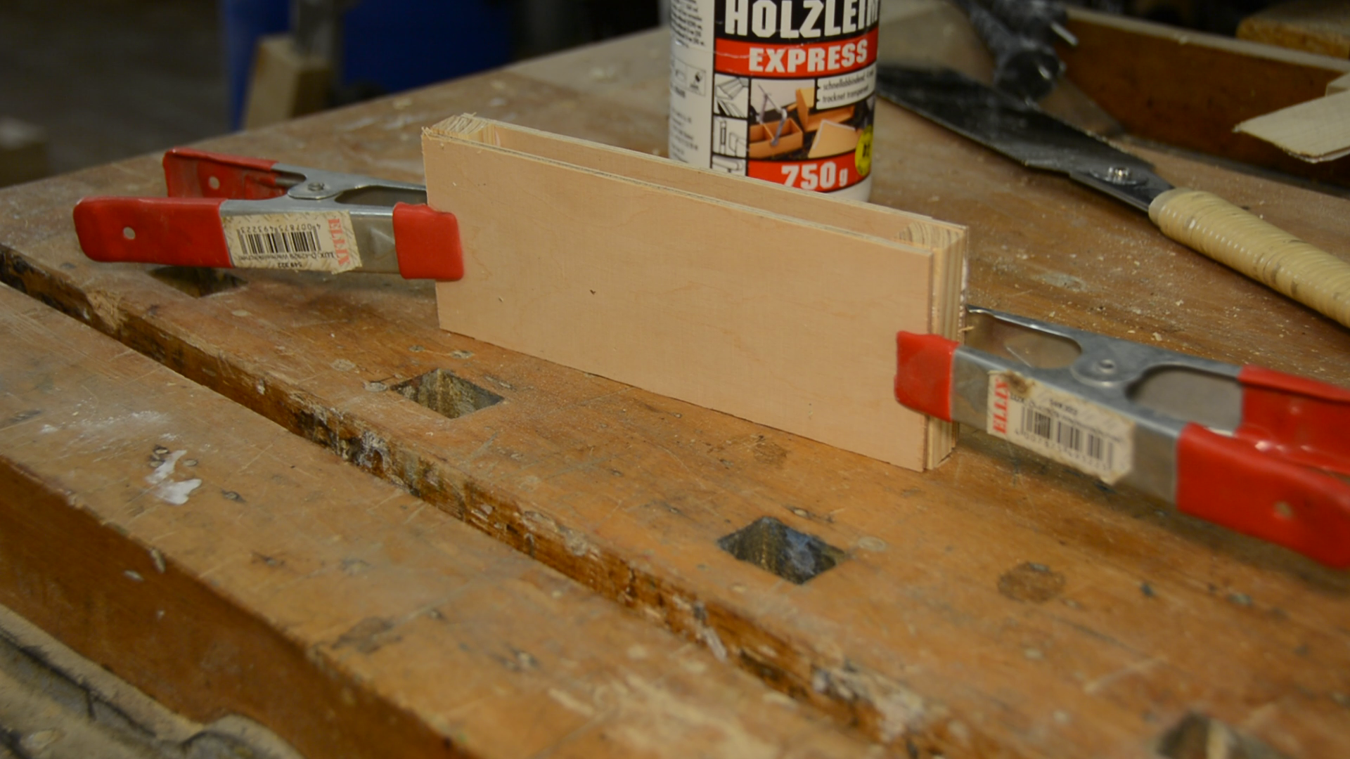
Creating a finger joint with a scroll saw would be an option but as the joint will not be visible there is an easier way to create the structure with hand tools: We cut a scrap piece of wood to a width of around 1 cm and to a thickness equal to the depth of the frame minus two times the material thickness of the MDF.
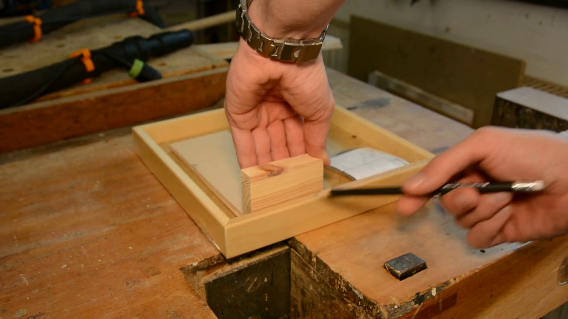
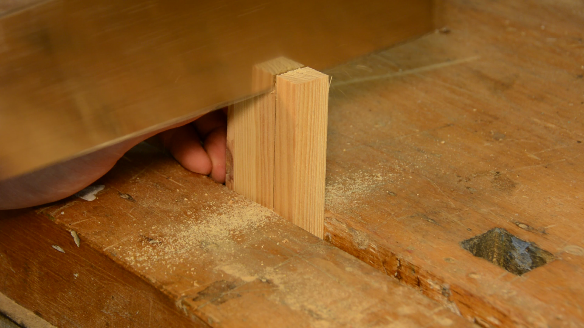
These spacers will later be glued between two thinner pieces to create the box.
Designing the wall mounted part
The design of the wall mounted part is very simple. It’s one part that has two third of the frame height and a width that is less than the 80% width of the box.
We subtract 2 times the material thickness for the sides of the box and another 2 times the material thickness for some wiggle room. The second piece has the same width and half the height of the first piece.
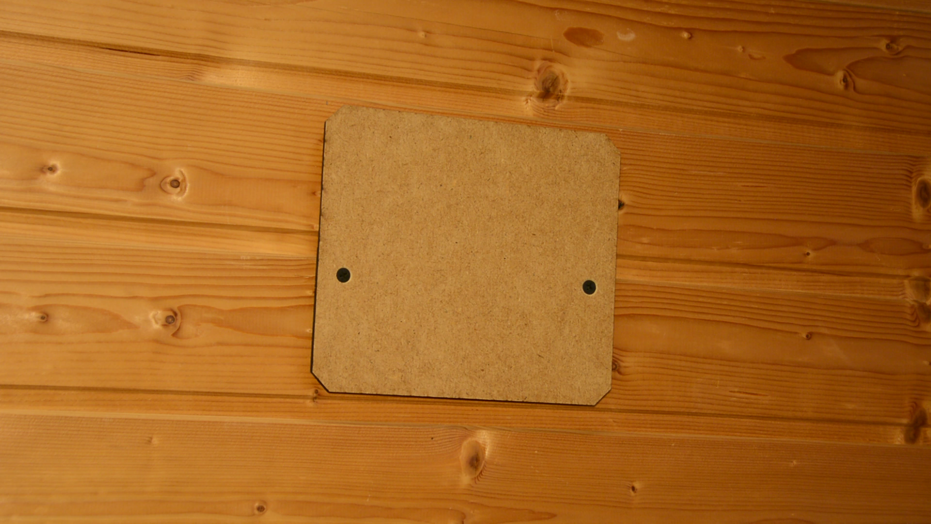
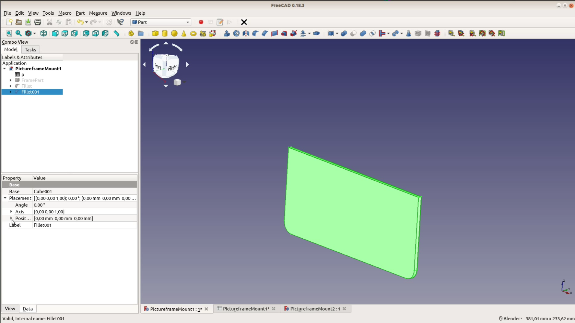
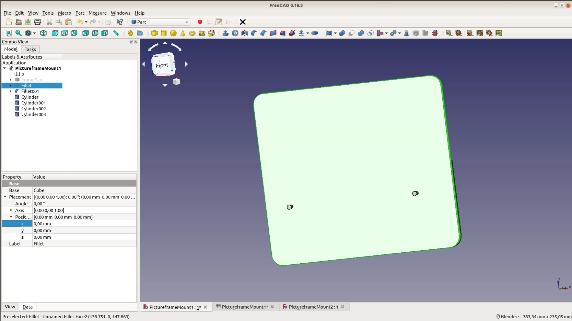
For a better look we round over the corners. We add two holes for the hanger by creating a cylinder and subtracting it from the parts with a boolean operation.
Without a laser just cut the pieces to the size given in the spreadsheet.
We are done in FreeCAD and can export the pieces with the LC interlocking workbench.

After exporting the first box we simply change the parameters in the spreadsheet. Then we recaculate all the objects and we can also export the box for the second picture frame.
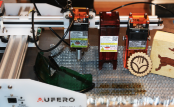
Cutting, modifying and assembling the parts
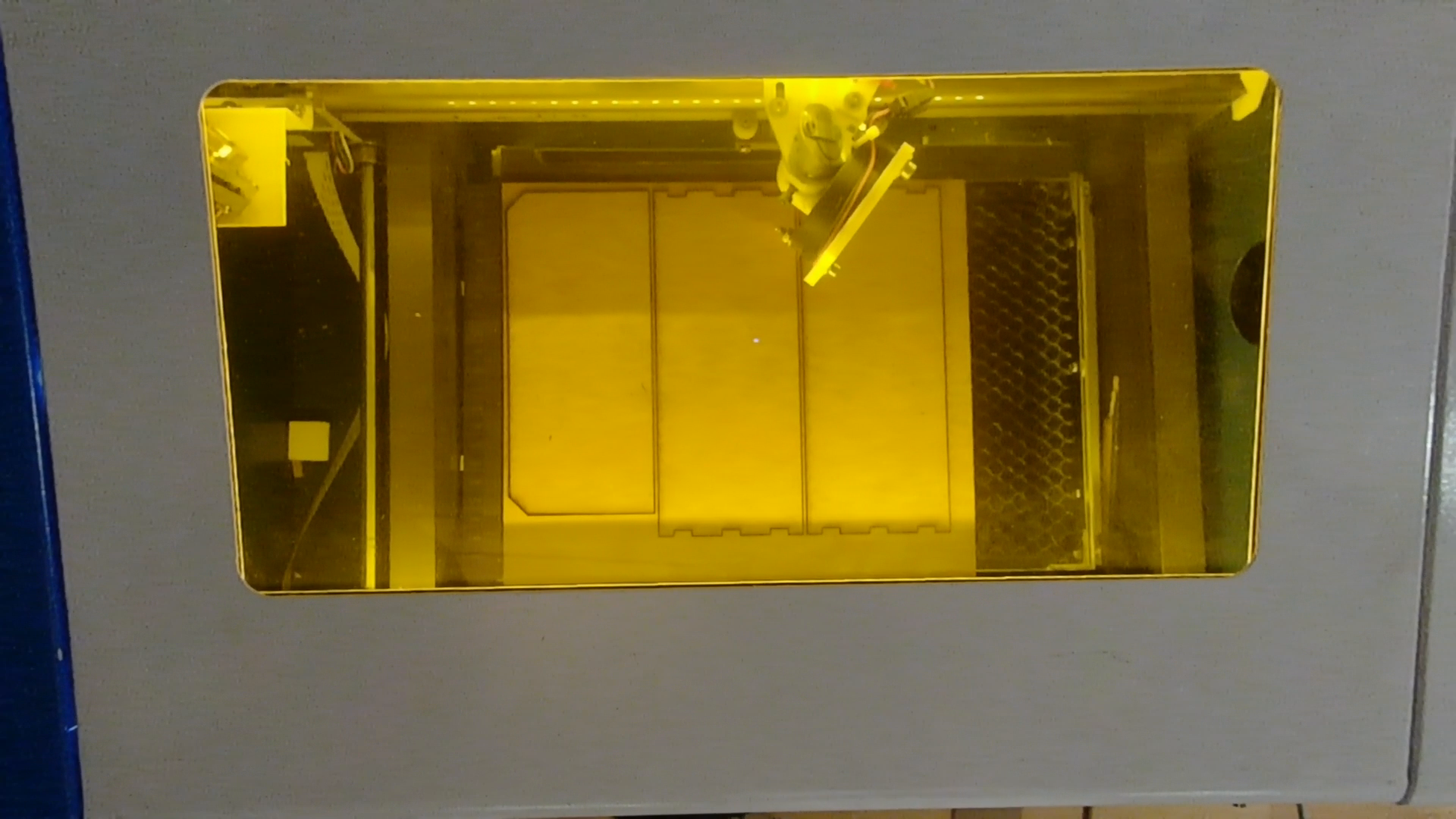
With K40Whisperer we cut the parts on the laser. We exported them in SVG and somehow the export ignored our holes and didn’t round over the corners properly.
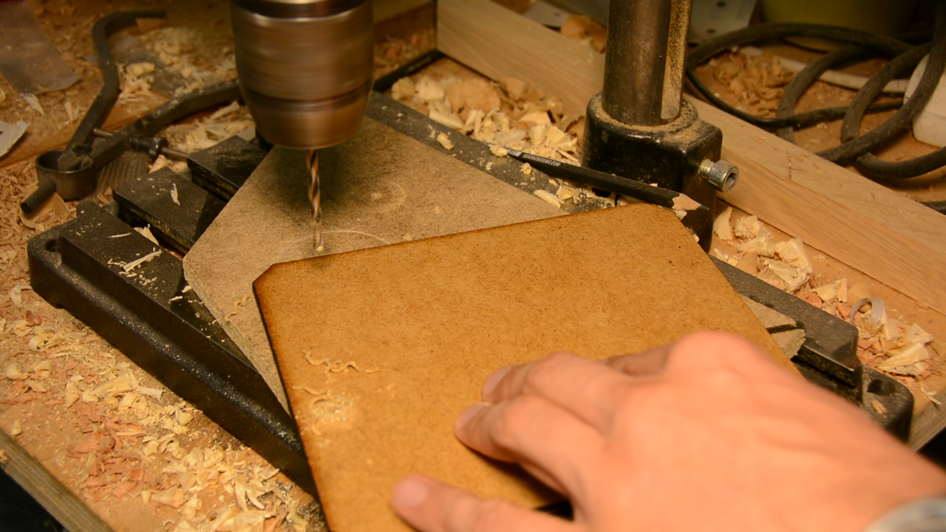
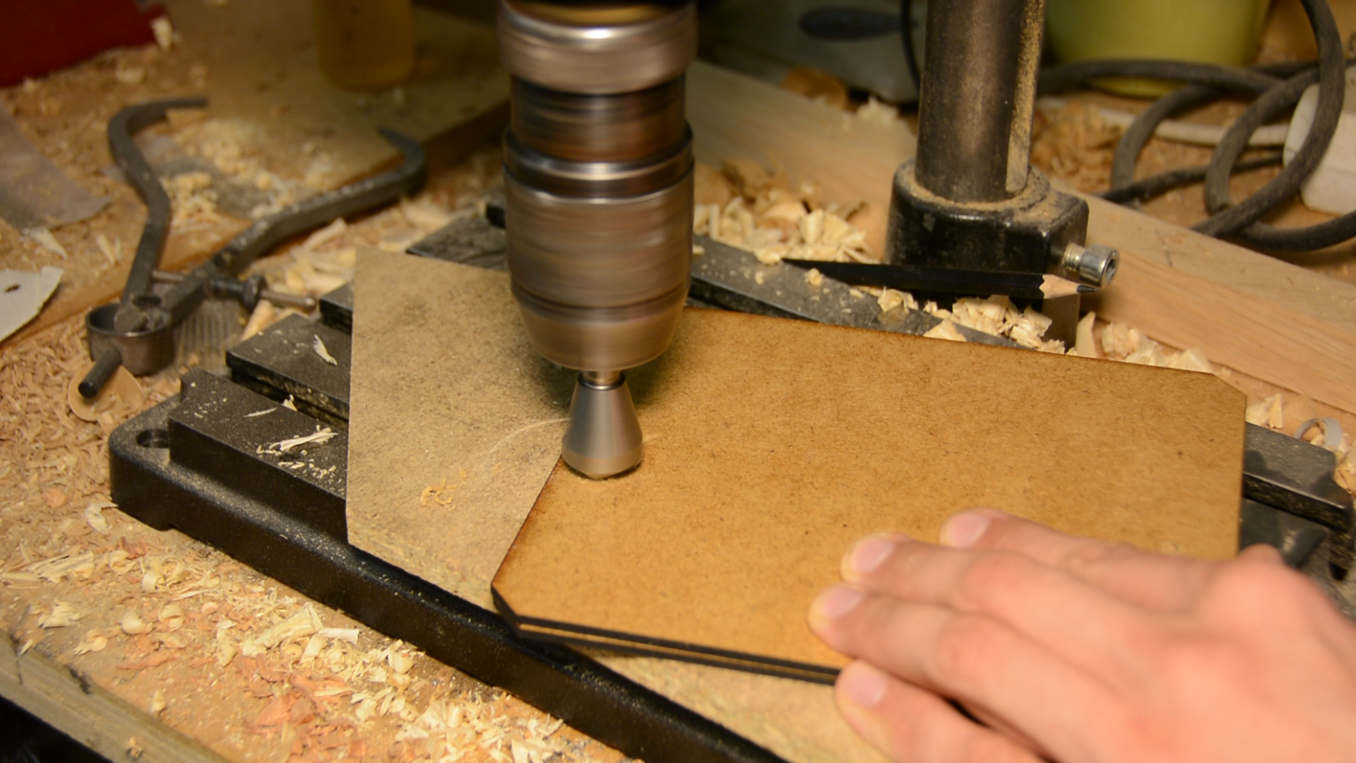
Next time we will use a DXF export and this time use a drill to bore the holes manually.
Even if you manage to export the holes properly: You still have to countersink them to ensure the two parts fit together nicely.
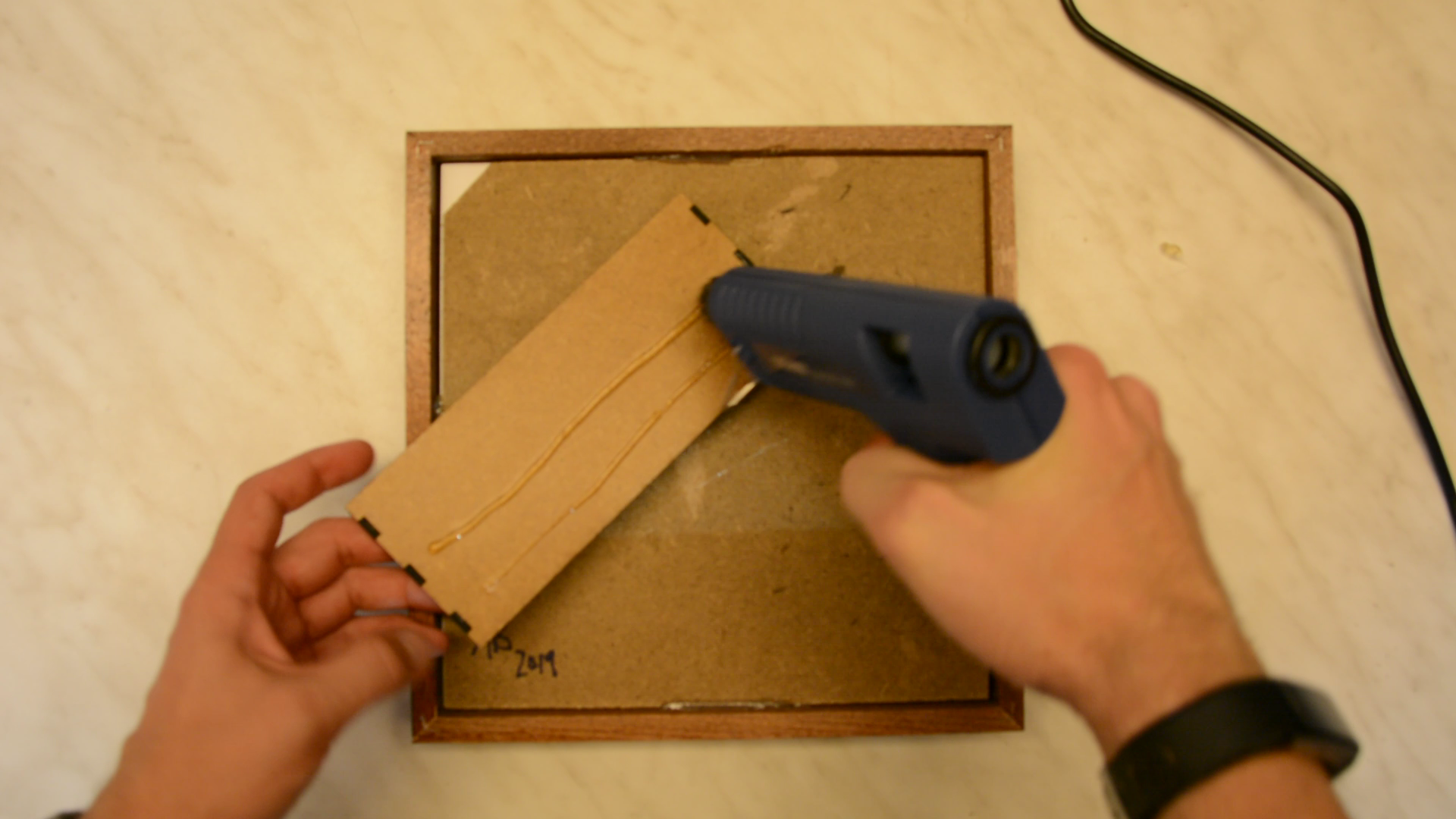
Now we can glue all the pieces together. On the right hand side picture you can see how the handtool version of the box is assembled.
We quickly noticed that the edges need a chamfer so that they sliding the picture in the holder is easier. Creating this chamfer on the wall mounted part is relatively easy with a block plane. You could also use a file or sandpaper.
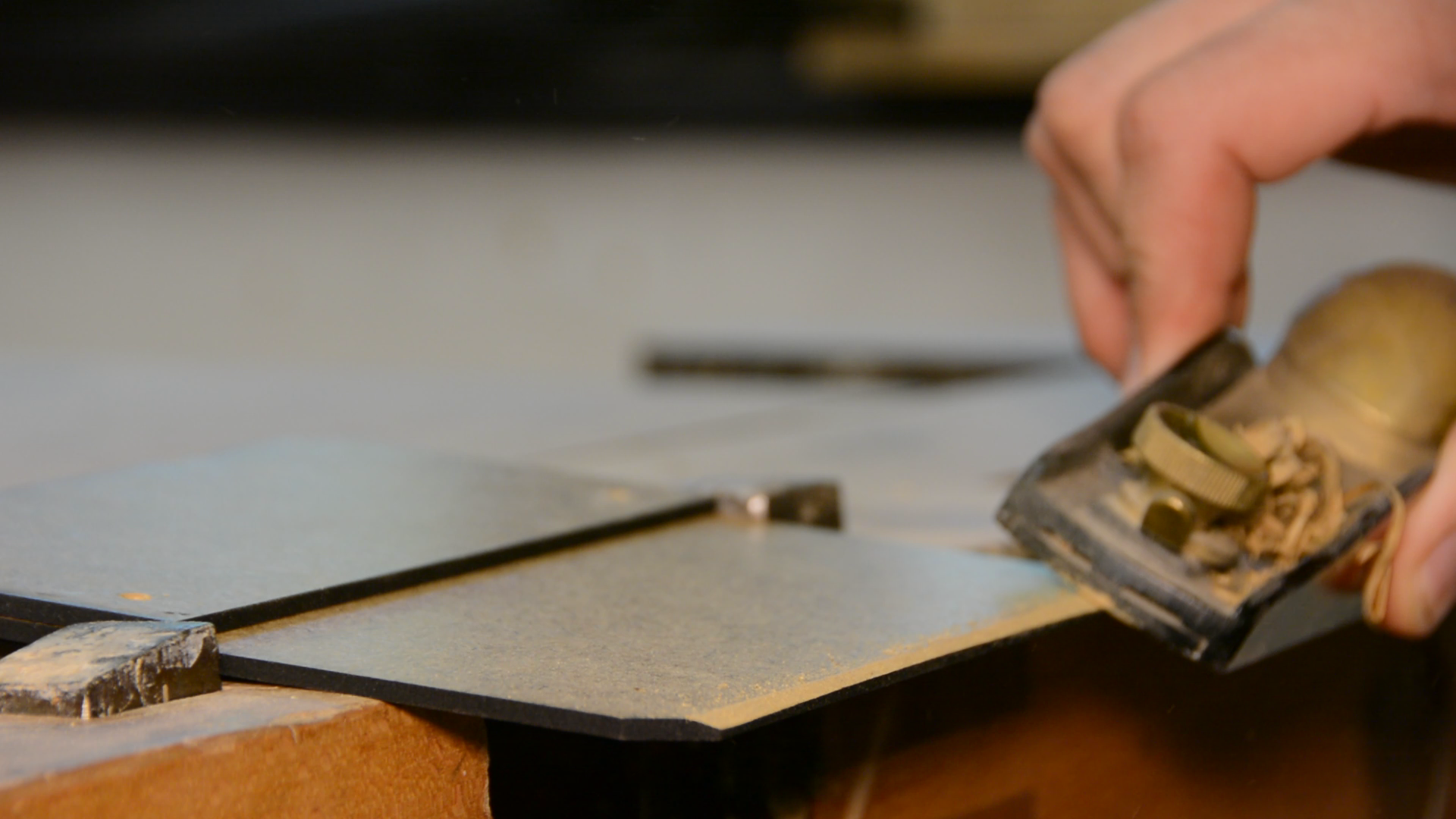
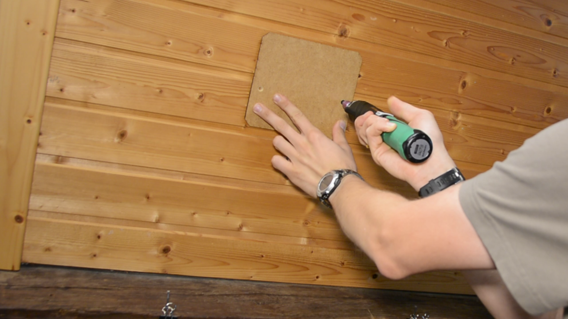
When creating the chamfer comes as an afterthought as in our case a Dremel or a manual file might be the only to get the job done.

Mounting the pictures to the sloped wall
We mount one part to the wall. If your wall isn’t covered with wood panels you will have to use drywall anchors or another type of fasteners and anchors.
We hot glue the box part to the backside of the picture frame.

Now we slip the picture frame over the mount and enjoy the picture on a sloping wall.