
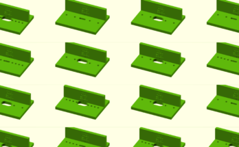
In this article we will design 3D objects for laser cutting using the free and open source CAD software FreeCAD. We will create a simple mounting bracket as an example.
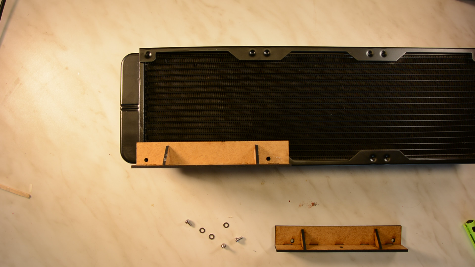
These mounting brackets are designed to hold the cooling unit of the K40 that we build here. This is a bit too complicated to model as a simple 2d model in Inkscape as we have shown
in this article
FreeCAD however is easily able to handle this design.
Enable laser cutting CAD in FreeCAD
The LC Interlocking Workbench is a great way to design even quite complicated shapes for the laser cutter. Install the workbench following the instructions on the website.

In FreeCAD we switch to the LC Interlocking workbench.
Designing the shape with the laser cut interlocking workbench
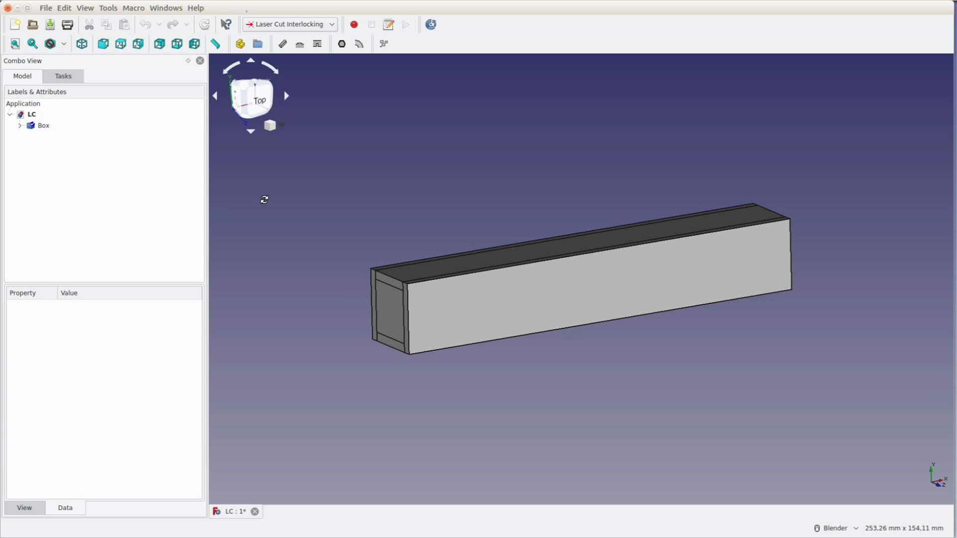
We want the mounts to have a length of 150 mm and the short sides to be around 25 mm wide. The box design tool from the workbench gives us a head start and creates the necessary pieces easily.
We just fill in the width, height, length of the box and the the thickness of the material – which is 3.1 millimeter – and get a box of that size.
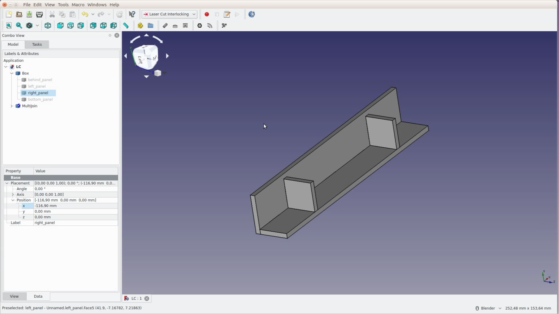
We delete the two sides that we don’t need with the delete key and position the two sides that later will become supporting elements 30 mm inwards.
To move objects by a set amount we add the respective number in the positioning area. Just type the plus sign and the number and let FreeCAD do the math for you.

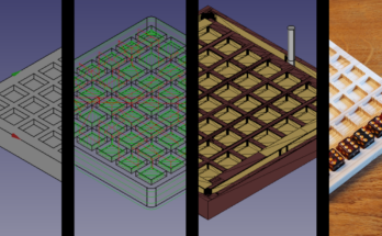
We then select all the pieces and click on the button to create connection tabs. In the task panel we add all parts to the assembly with the add same parts button. By pressing space we hide one long piece and mark the faces of two short pieces so that they get tabs.
While for the short sides the default setting of a single tab works fine we increase the amount of tabs for the long sides to five.
After hiding the second long side we can add the other two faces and after closing the task panel all the tabs are created.
Refinement with the parts design workbench
Now we switch back to the part design workbench to modify the pieces. Before we can modify a shape we have to convert it into a body with the button showing a blue staircase.
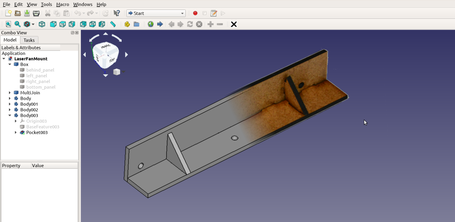
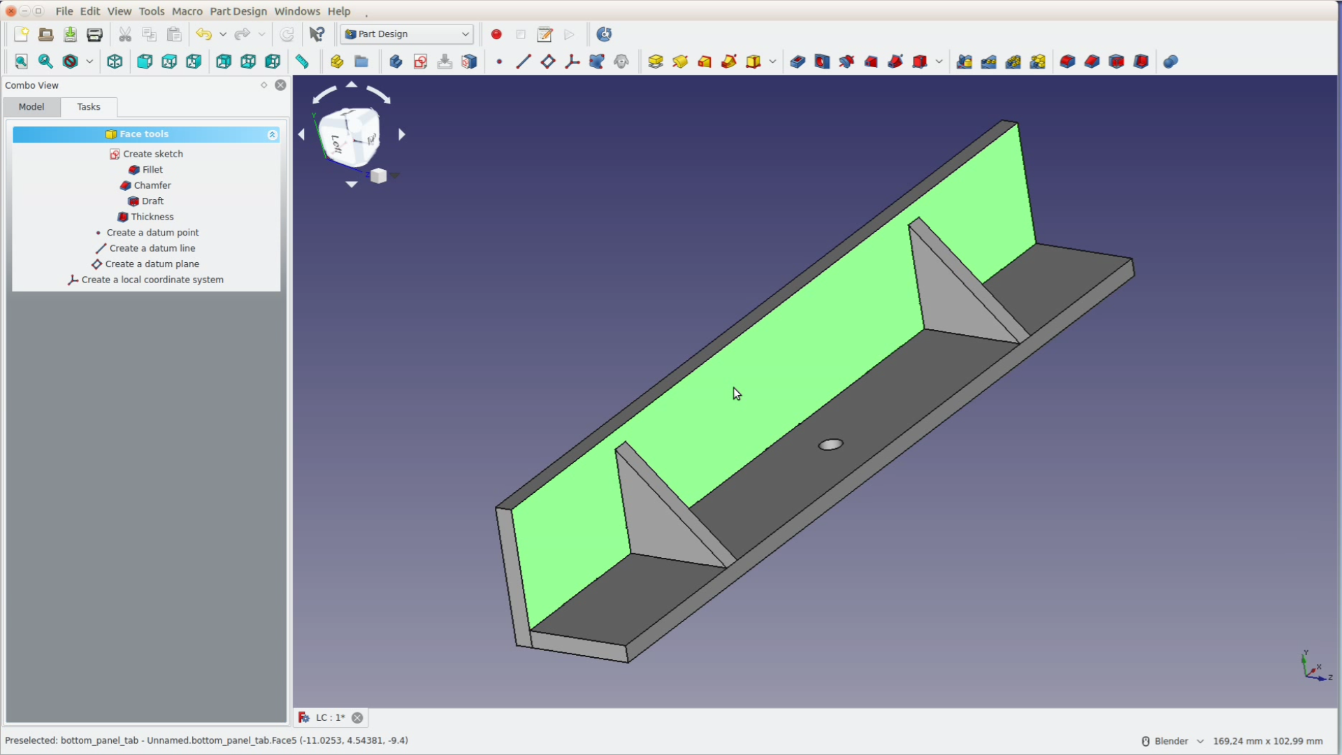
For the smaller pieces we create a sketch on their surface and then use the button with the blue box to get the corners of the shape as a reference.
With the multiline tool we then draw a triangle and directly close the sketch.
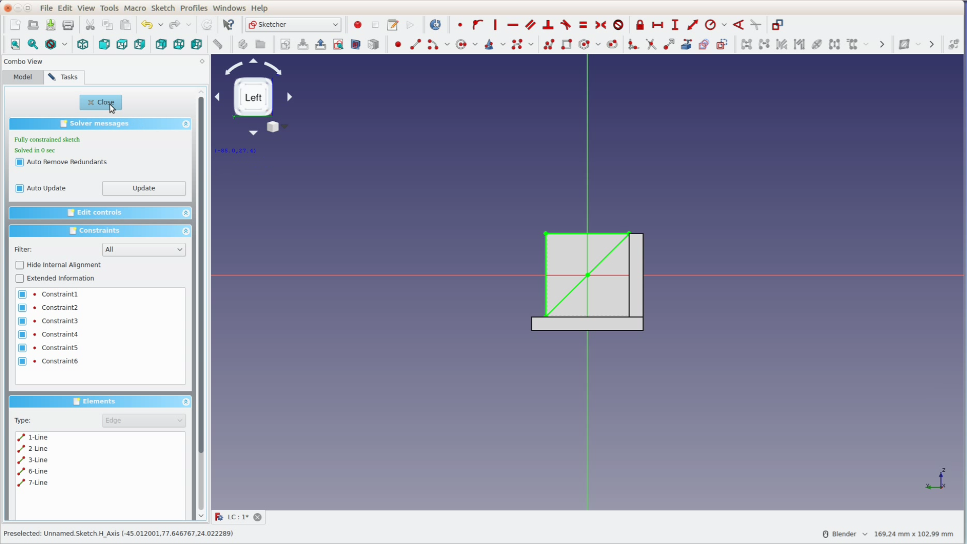
By pocketing the triangle through the entire structure we cut away part of the shape. This change is purely for the look.
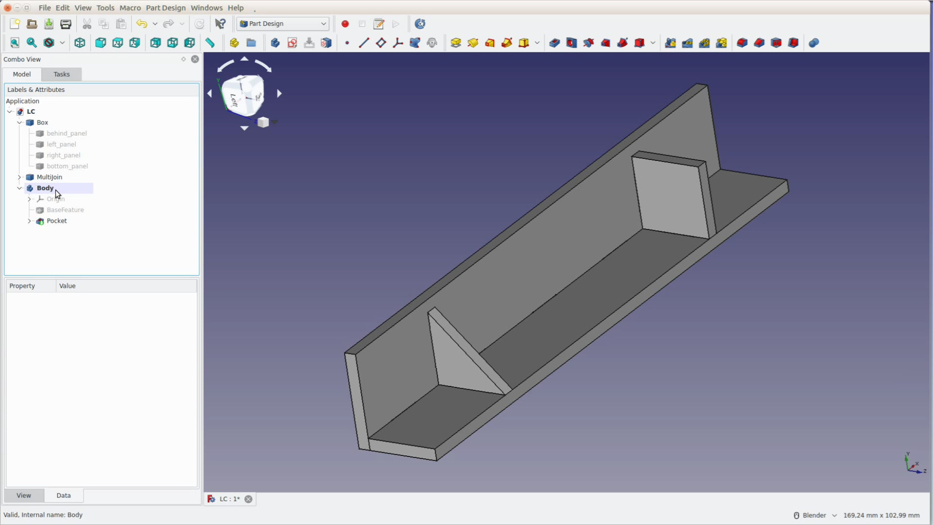
We repeat the same steps for the other supporting structure.
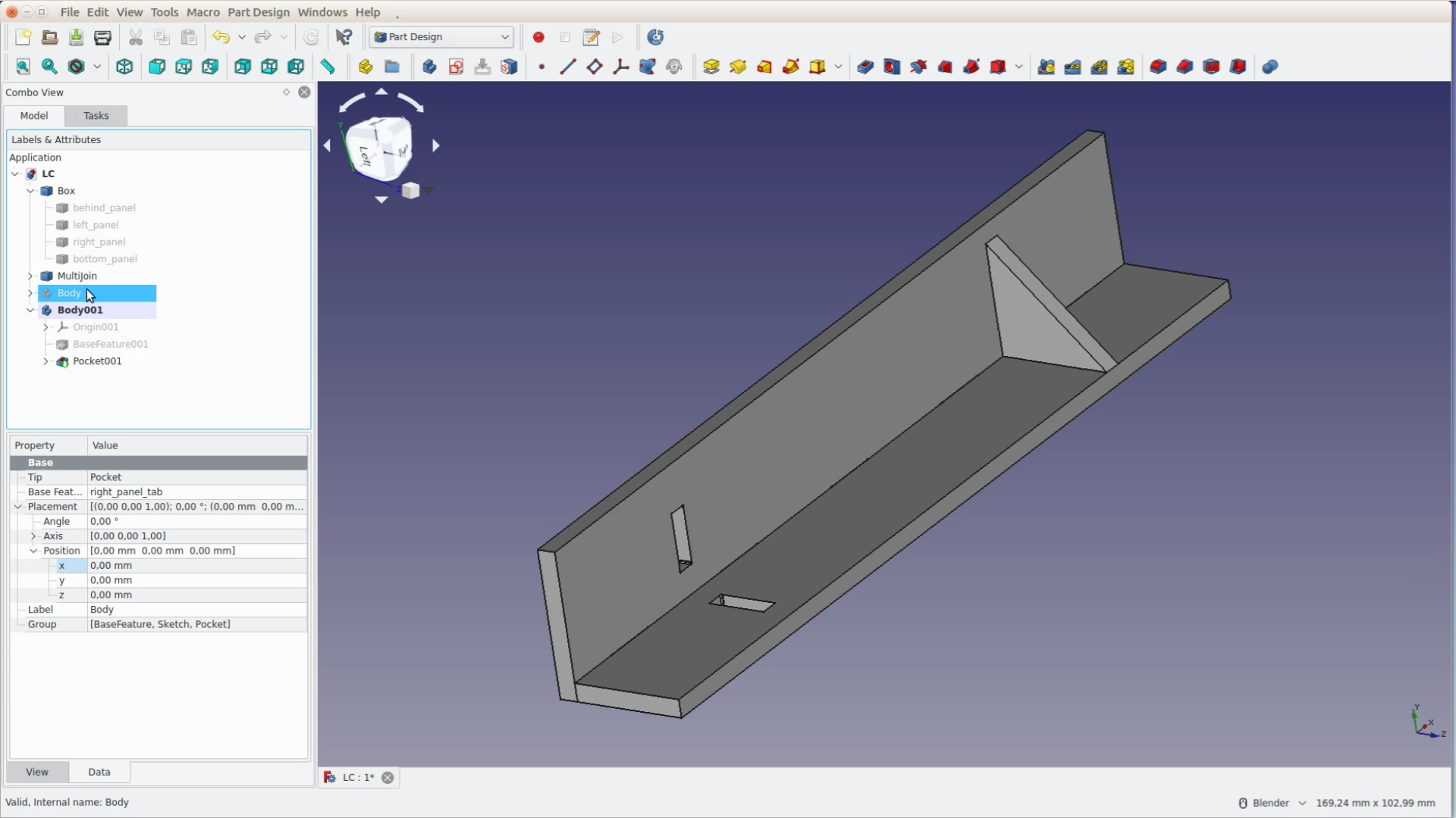
The two long pieces get holes to mount the cooling unit and screw the mount to the cart. These are also sketches on the surface that are then pocketed through the piece.
Creating sketches in FreeCAD follows a simple logic. If you get close to an existing point and it turns yellow the point is catched and a constraint is automatically created.
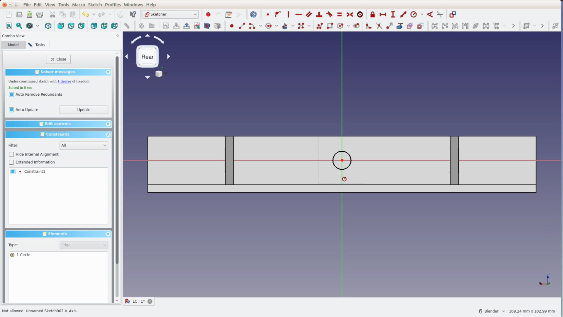
Now the circle still has an arbitrary size. We select the circle and add a constraint to make its radius 2mm. We close the sketch and pocket the hole though all the material.
On the other piece we first create two circles that have an arbitrary size and position. Then we constrain them.
In a first step we mark both centers and make sure they are on the same height with a horizontal constraint.

When selecting both circles the radius constraint is automatically applied to both elements. We measured the distance of the mounting holes of the radiator to be 120 mm – which is a horizontal distance constraint.
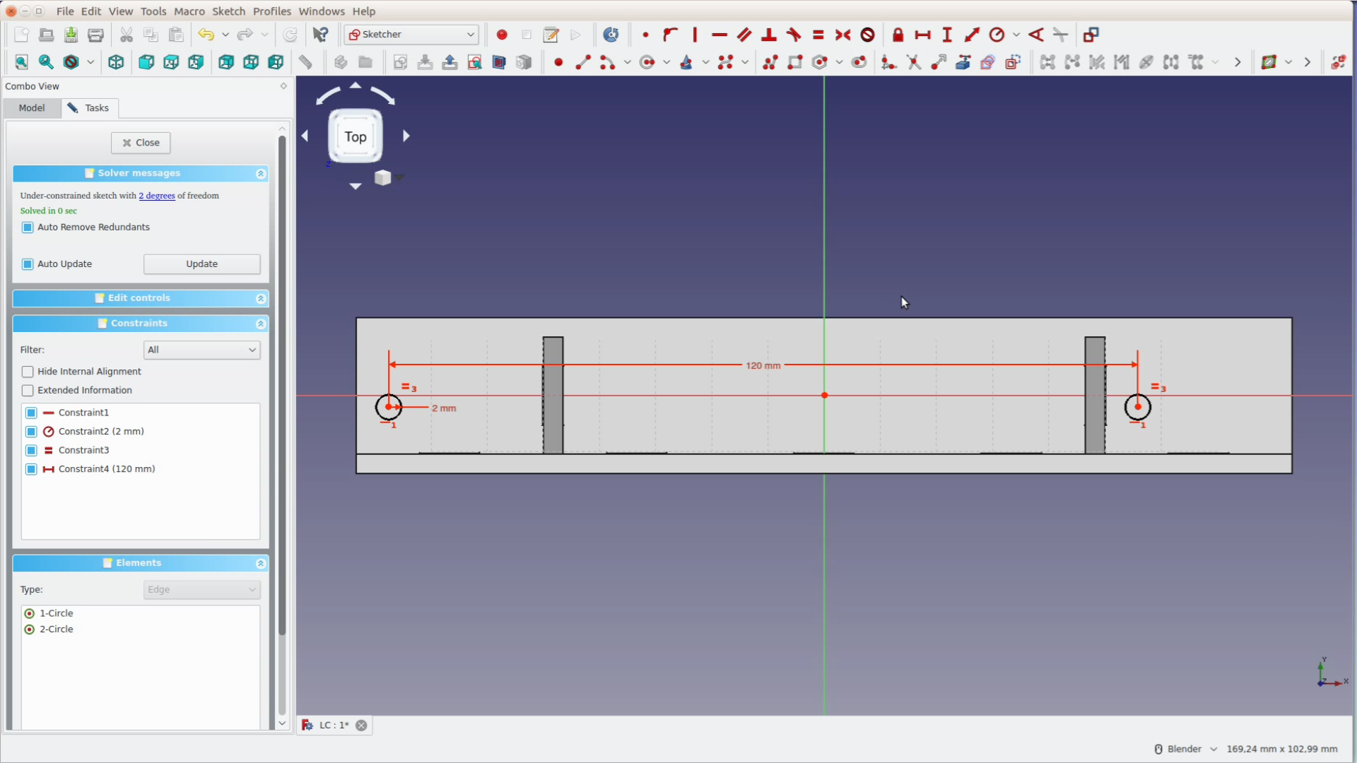
We then again use the blue box icon to get the edge of the shape as a reference so that we can measure the horizontal distance of 7,5 mm and the vertical distance of 10 mm.

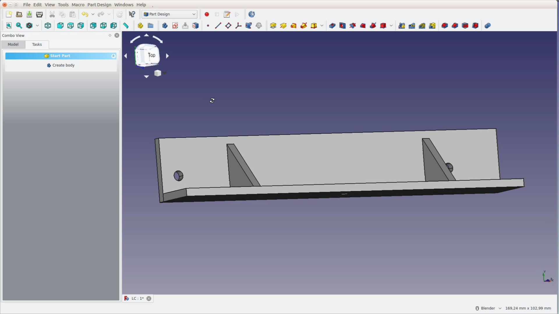
After closing the sketch we selet pocket and go though all the material. We finish the shape and can inspect it from all sides.
Laser cutting
In order to cut them on the laser we select all the parts and go back to the LC Interlocking workbench. A very cool feature is this button with the small squared that puts all pieces flat in one plane.

We export these shapes to a DXF file and can cut them on the K40.
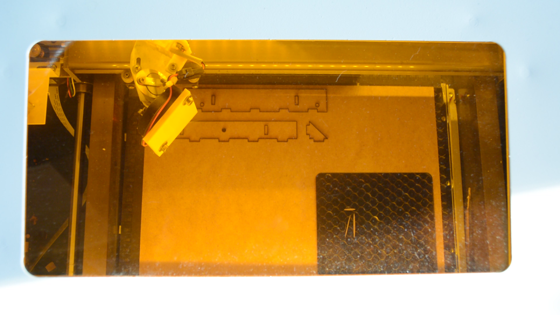
After that we cut the parts out the mounting brackets are ready for glue up.
I’m new to CAD so maybe I’m missing something basic here… but I’m struggling in refining the parts in the Part Design Workbench.
I select a panel and click on the blue staircase tool – Create a new body. I click on Create a Sketch, but it will only let me select one of the coordinate planes (not the panel surface) for drawing the sketch. I cannot link any of the panel edges with the external geometry tool.
Is there something I’m missing?
You will have to select the face you want the sketch on first and then click on create sketch. I will then be placed on the respective surface.