

In this article we improve the cooling of the K40 laser cutter and monitor the water temperature and flow rate with an Arduino.
The cooling mechanism of the K40 out of the box is actually working quite well. With a large water tank and some cool packs in the water the laser can cut for maybe 15 to 20 minutes without getting hot.When we created all the parts for our soda bottle rockets we exceeded this time and had to stop several times as the water was getting quite hot. Ideally it should be around 20 degrees.

Active K40 cooling
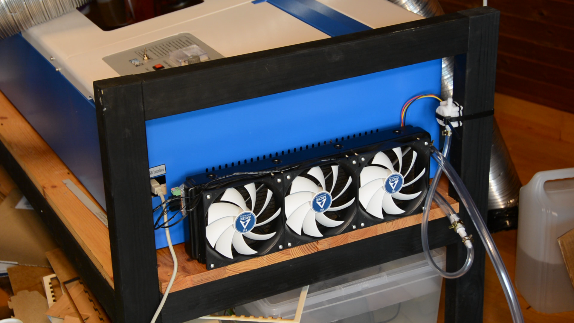
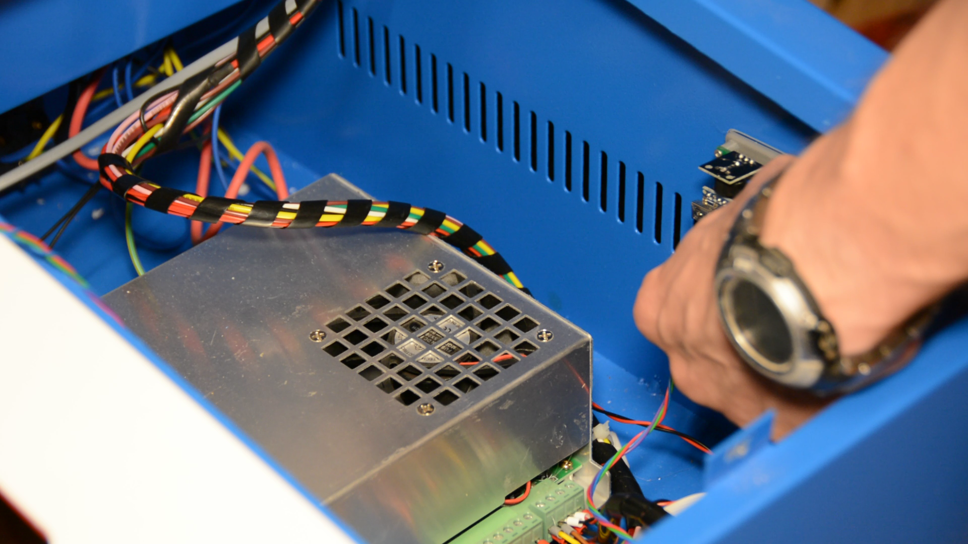
In order to be able to use the laser cutter a bit longer we wanted to add an active cooling mechanism. We start with a radiator and three fans used for water cooling desktop computers. The fans are simply screwed on the radiator. All the products are linked at the end of this article.
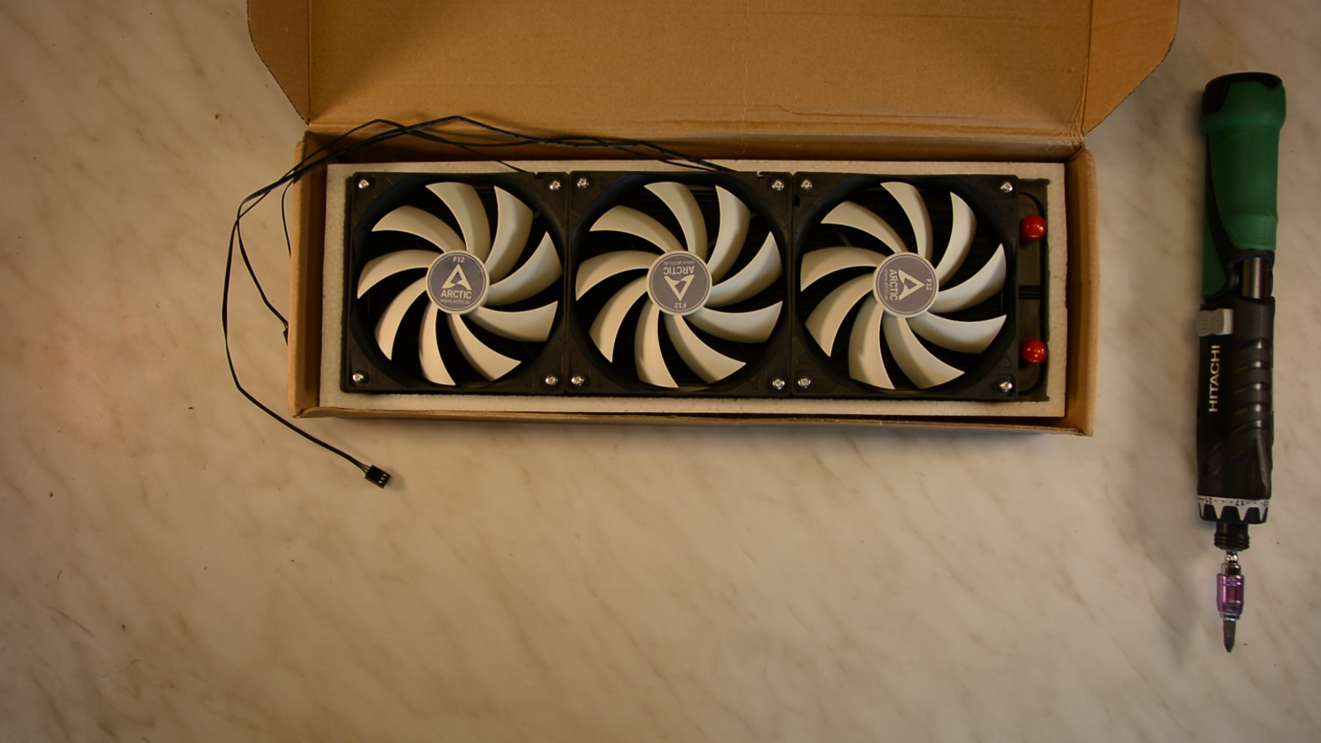
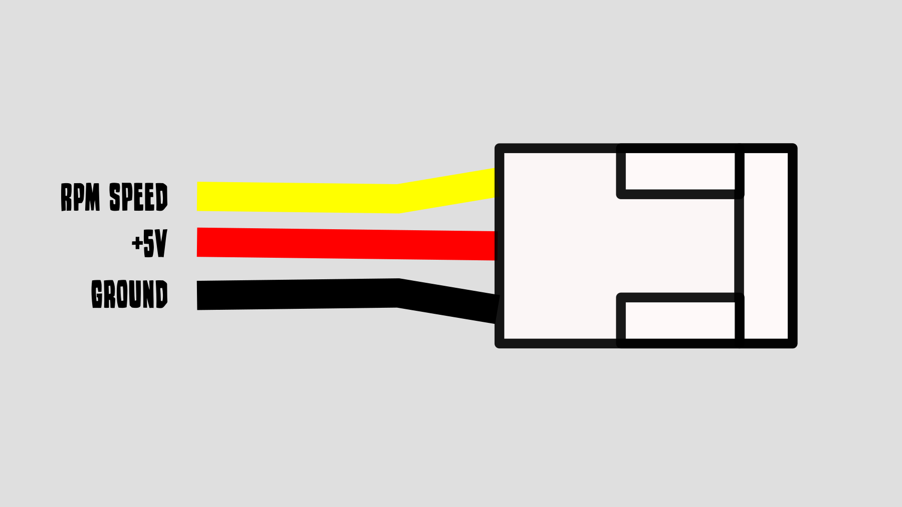
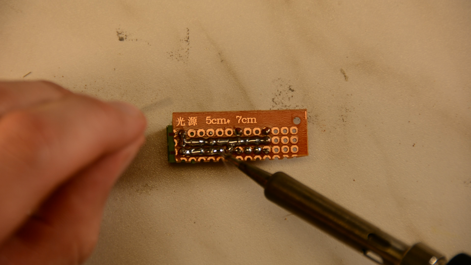
The fans come with connectors that have power on the middle pin and ground on one of the outside pins. You could connect these wires with a wirenut or a Wago clamp if you don’t want to solder. We soldered some pin headers to a piece of perfboard so that we can easily swap one of the fans or disconnect it.
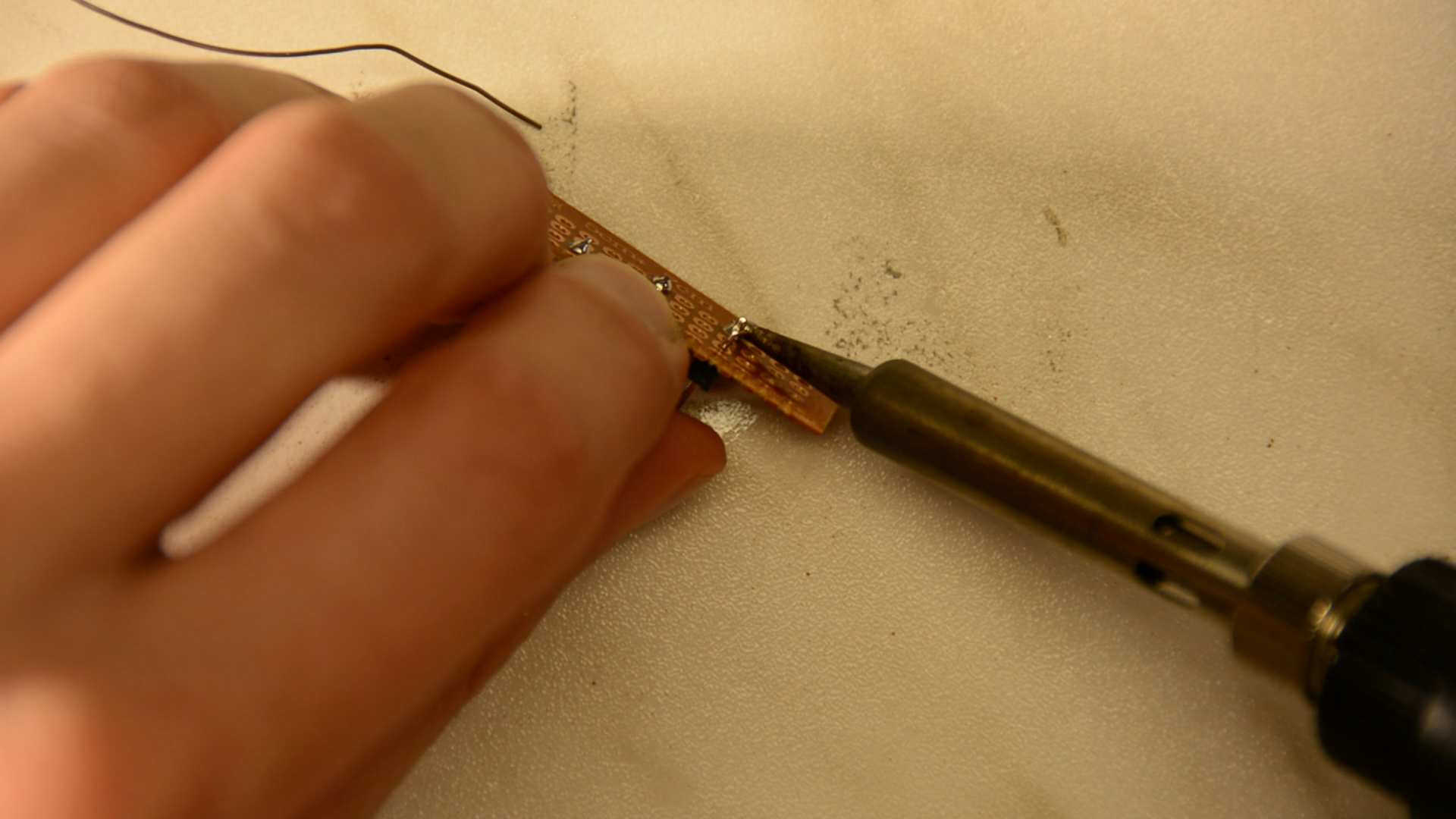
Power will later be connected to the screwclamp that is also soldered to the perfboard.
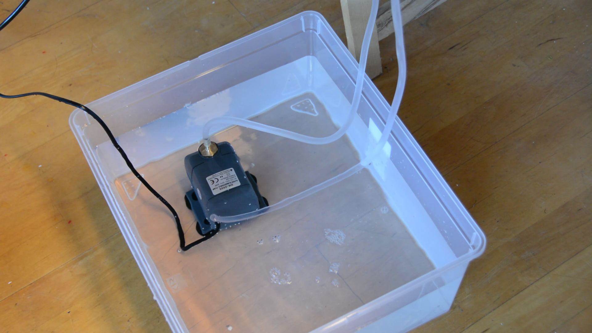
Now let’s connect the fans to the laser, the aquarium pump and a flow sensor.
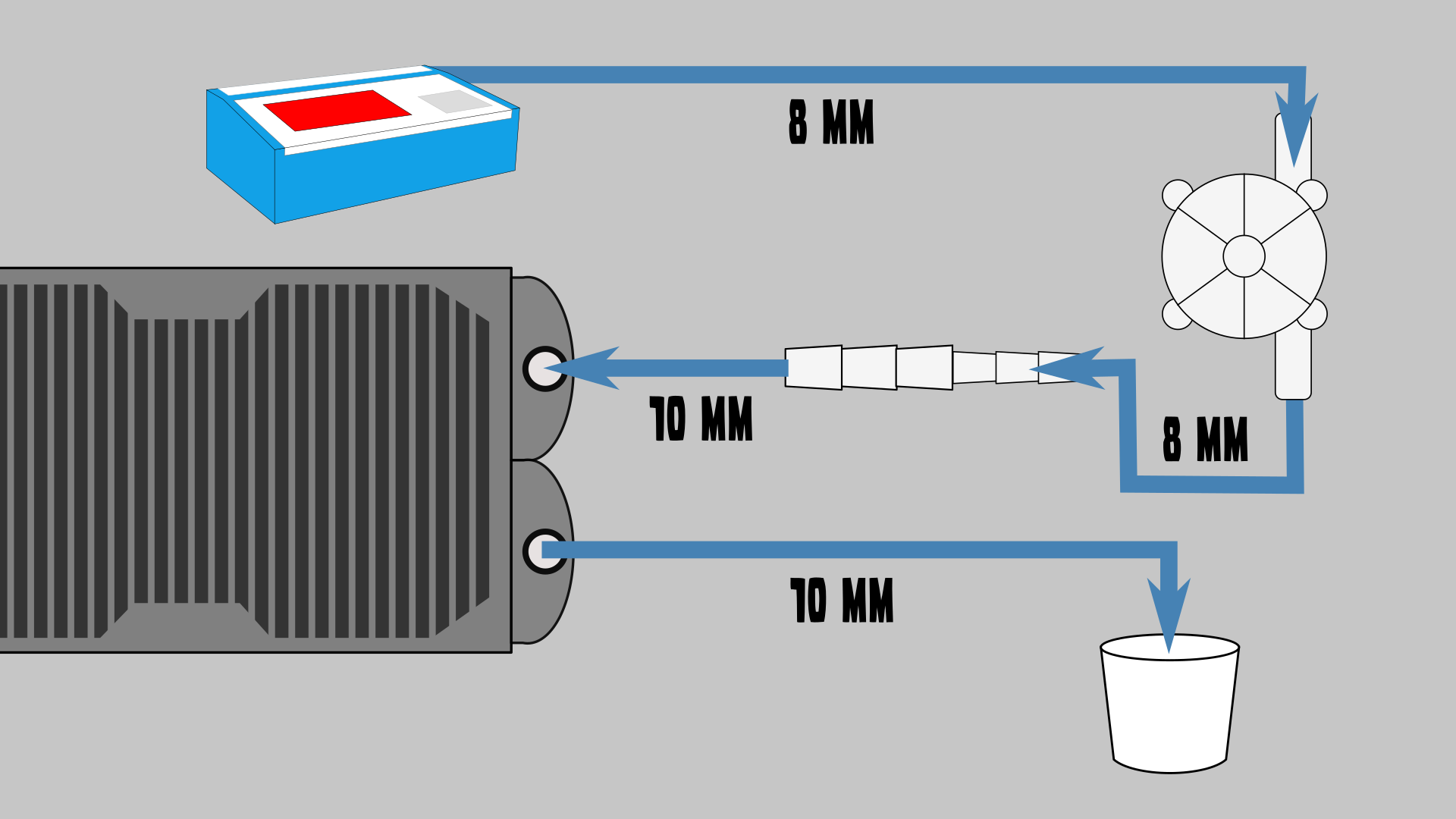
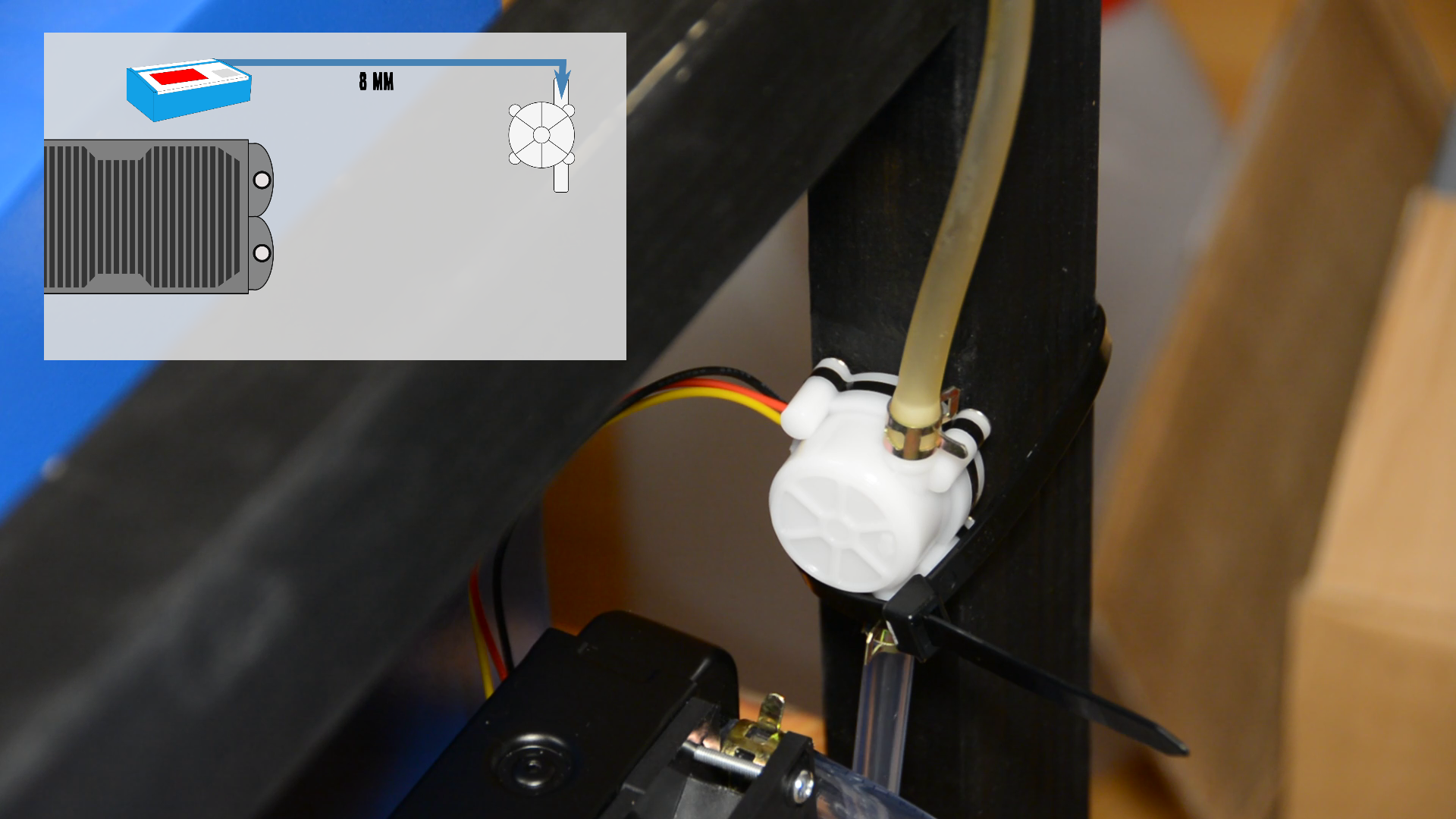
The flow sensor is later mounted with a zip tie to the laser cart. We use small hose clamps to connect the existing hose to a flow sensor, the 8mm hose of the flow sensor goes to an adapter and the 10mm end of the adapter goes to the radiator.
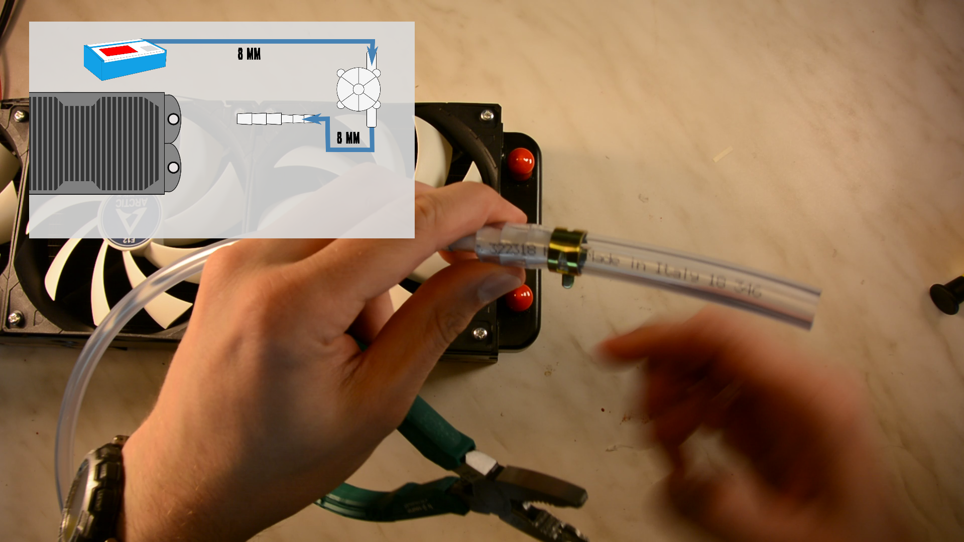
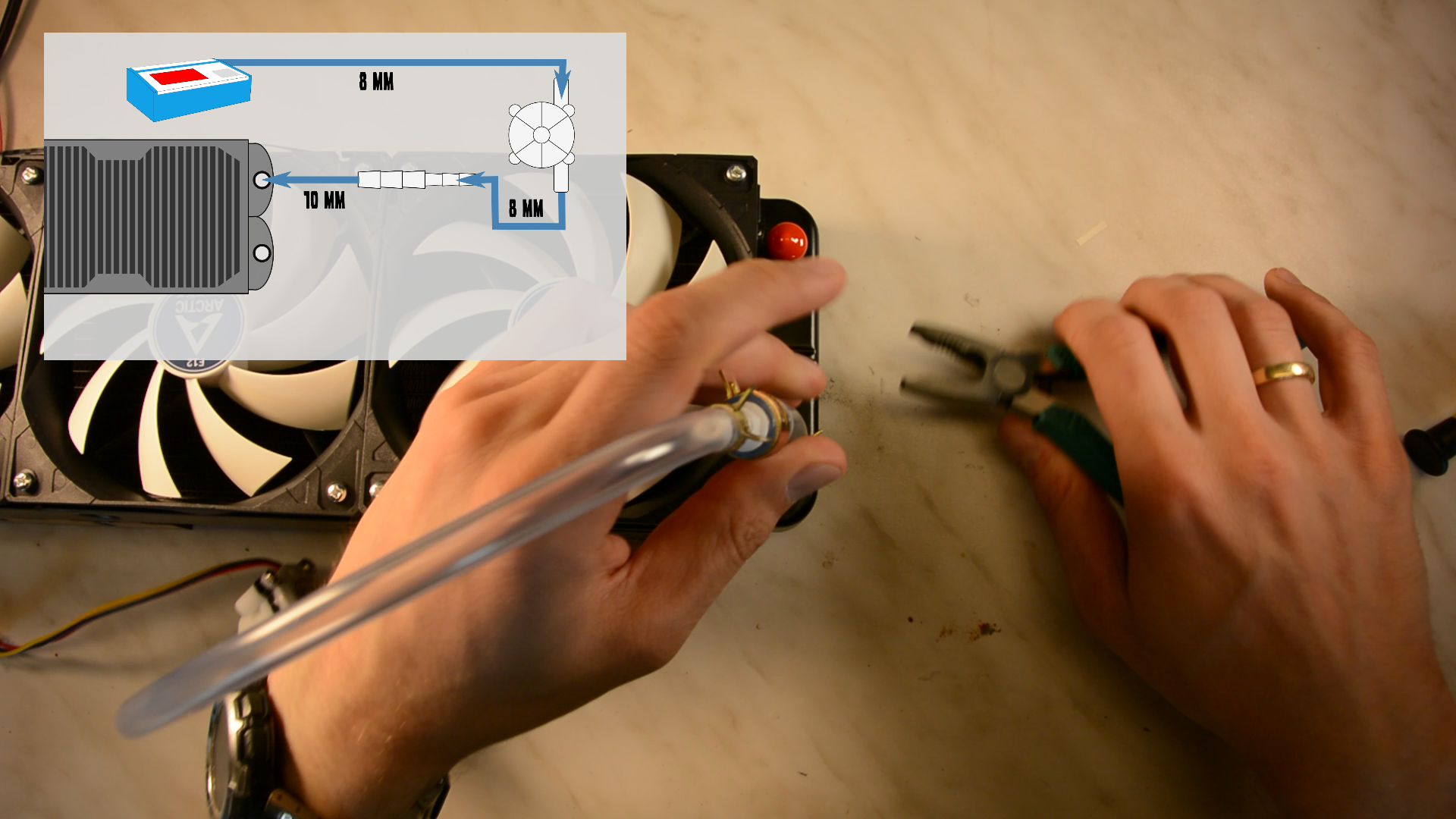
Another 10 mm hose from the radiators goes to the water reservoir.

First we tried to be smart and cheap and printed the adapter ourselves from a thingiverse design. This worked somehow.
However for the adapter to be water tight and not break we had to work with quite some wall thickness. This lead to a rather low flow rate. So later we replaced the DIY version with an adapter from ebay and easily doubled flow rate with the larger diameter. So this is not the place to save 3 bucks.


Mounting the fan
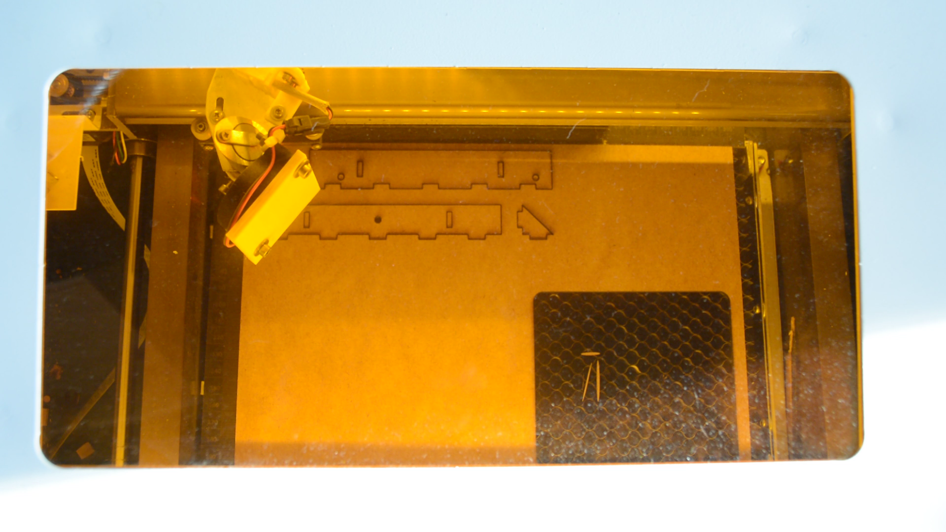
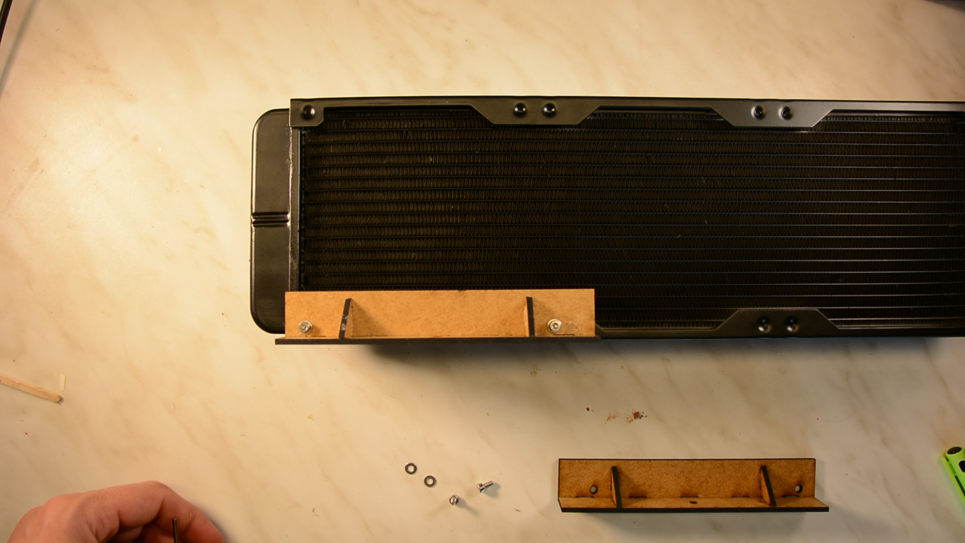
We want to mount the fans to the laser cart and designed brackets that we cut from MDF.
The MDF pieces are glued together with normal wood glue.
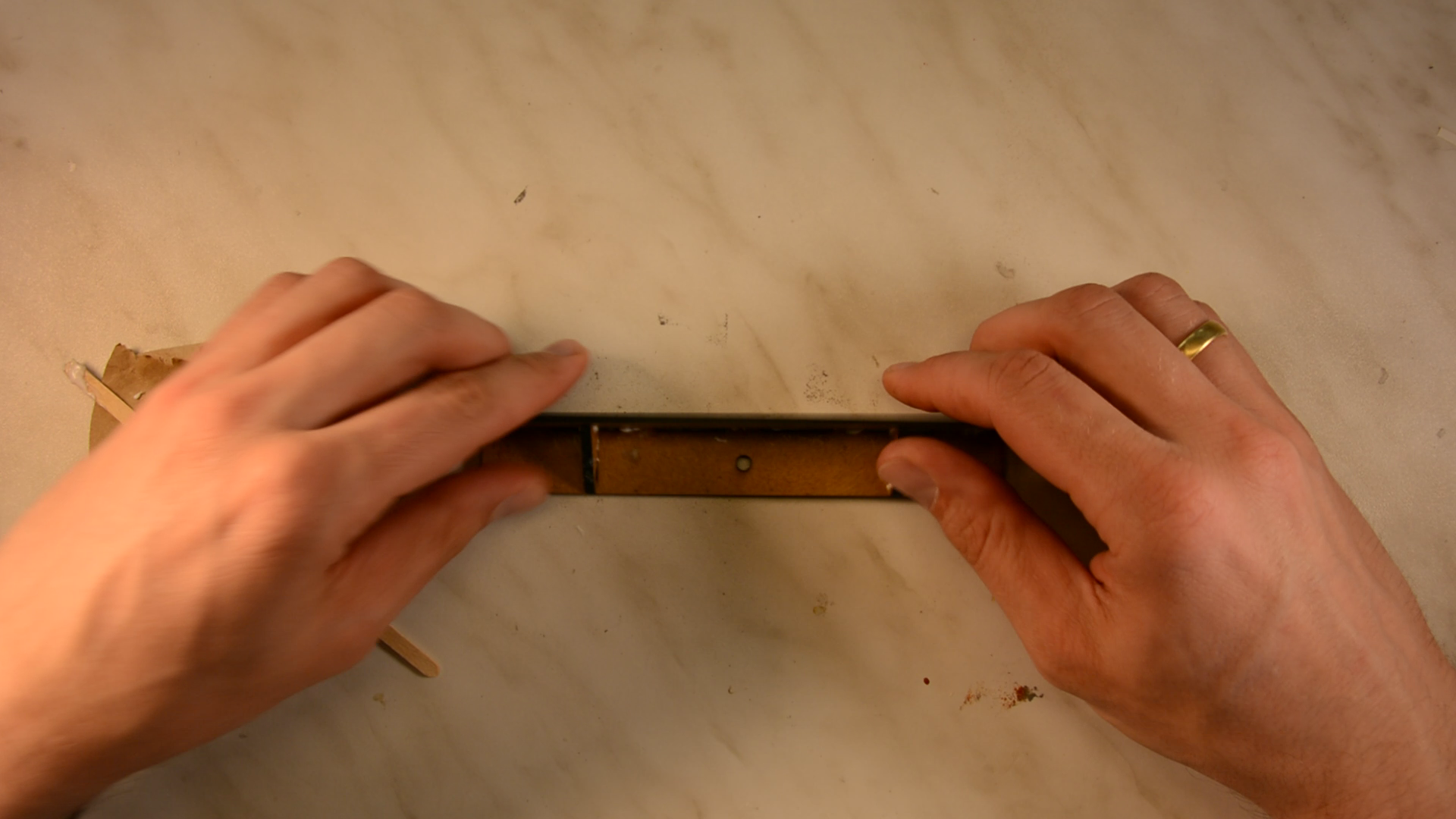
These brackets are screwed to the radiator and can then be screwed to the cart.
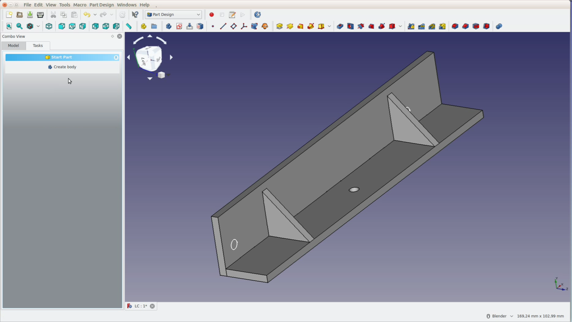
There will be a separate article on how we designed them in FreeCAD coming soon.
Power the fan
To power the fans we connect one end of a cable to the screw terminal.

The other end is connected to the same 12 volt step down converter we are using for the air assist. Have a look at the air assist article how to install the step down converter.
Digital control and monitoring with an arduino
If you only want cooling you can consider this project done. We want to take it a step further and monitor the flow rate, the temperature of the water and get an acoustic warning signal if something is wrong.

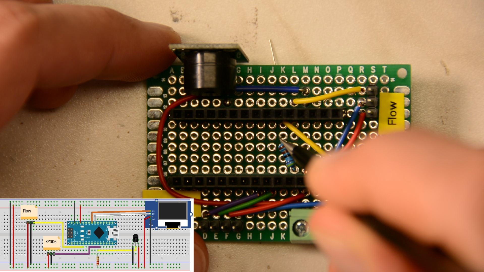
Here you see the entire set of the electronics on a breadboard. It is only a handful of components that are controlled by an Arduino. The temperature sensor is the cable in the lower left corner and the flow meter is the small white part connected to the tube. The current values are displayed on an OLED display and a buzzer signals if the temperature is too high or the flow rate too low.

This fritzing sketch as well as all the very bad code copied together from various samples and a list of components can be found here:

And here is the source code that is copied straight from some sample files and looks really ugly: k40_cooling
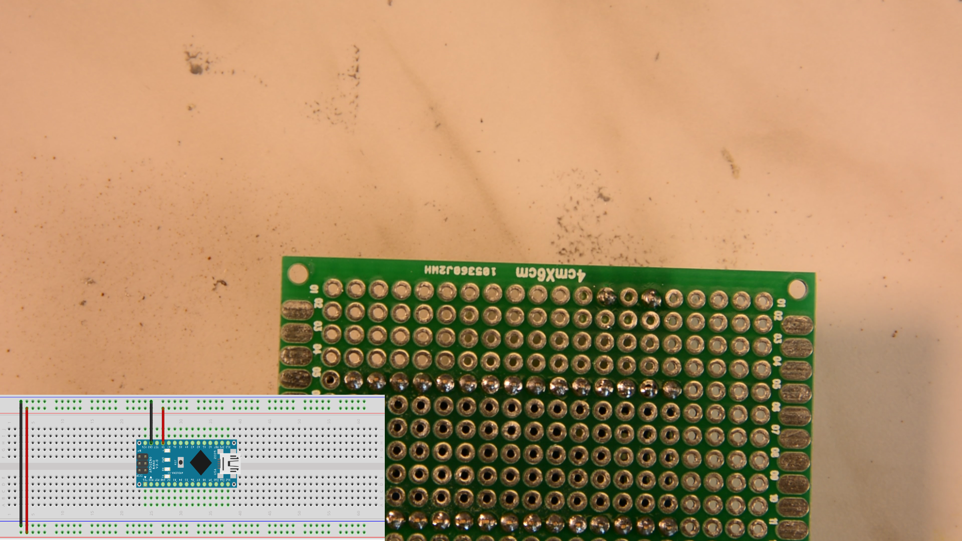
First we solder a pin socket for the Arduino nano and a screw terminal for the power connection the perfboard.
We then connect the buzzer with all its connections.
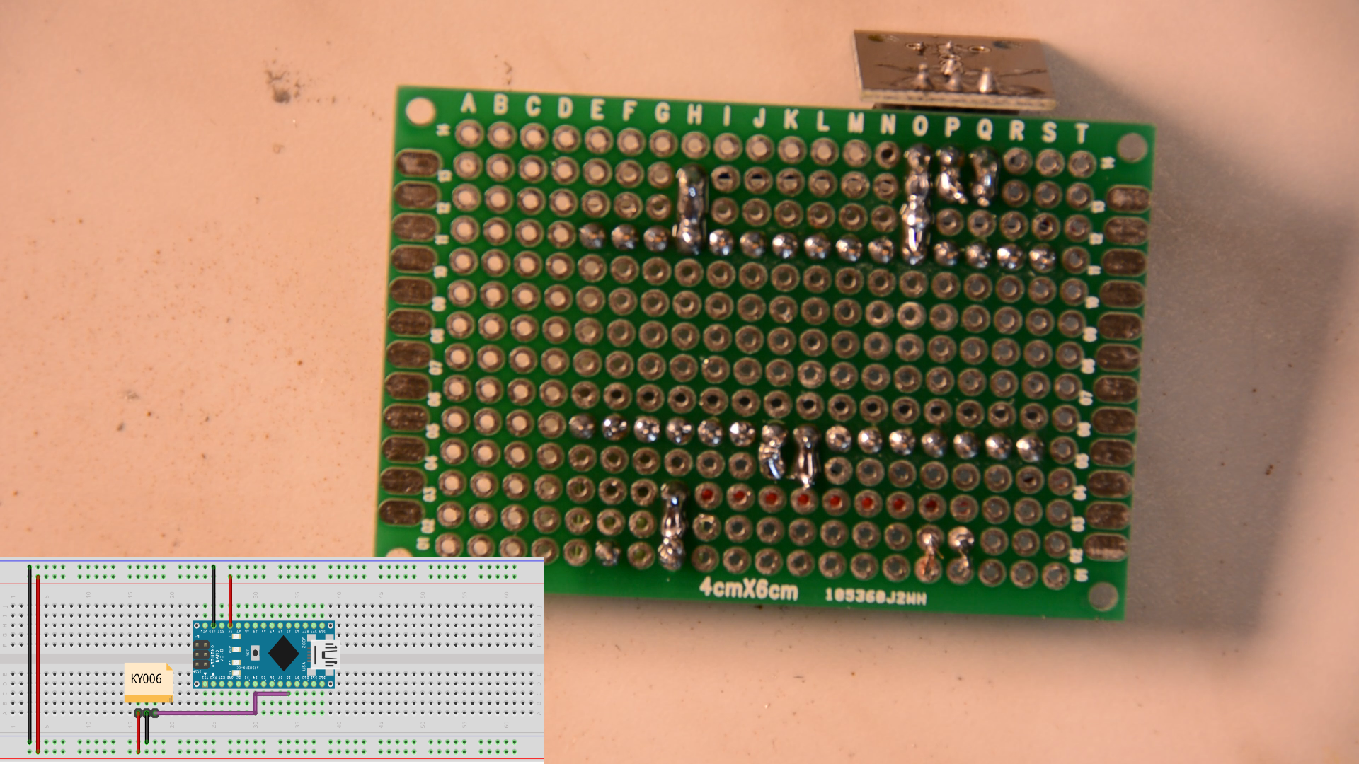
Next come 4 pins for the display.
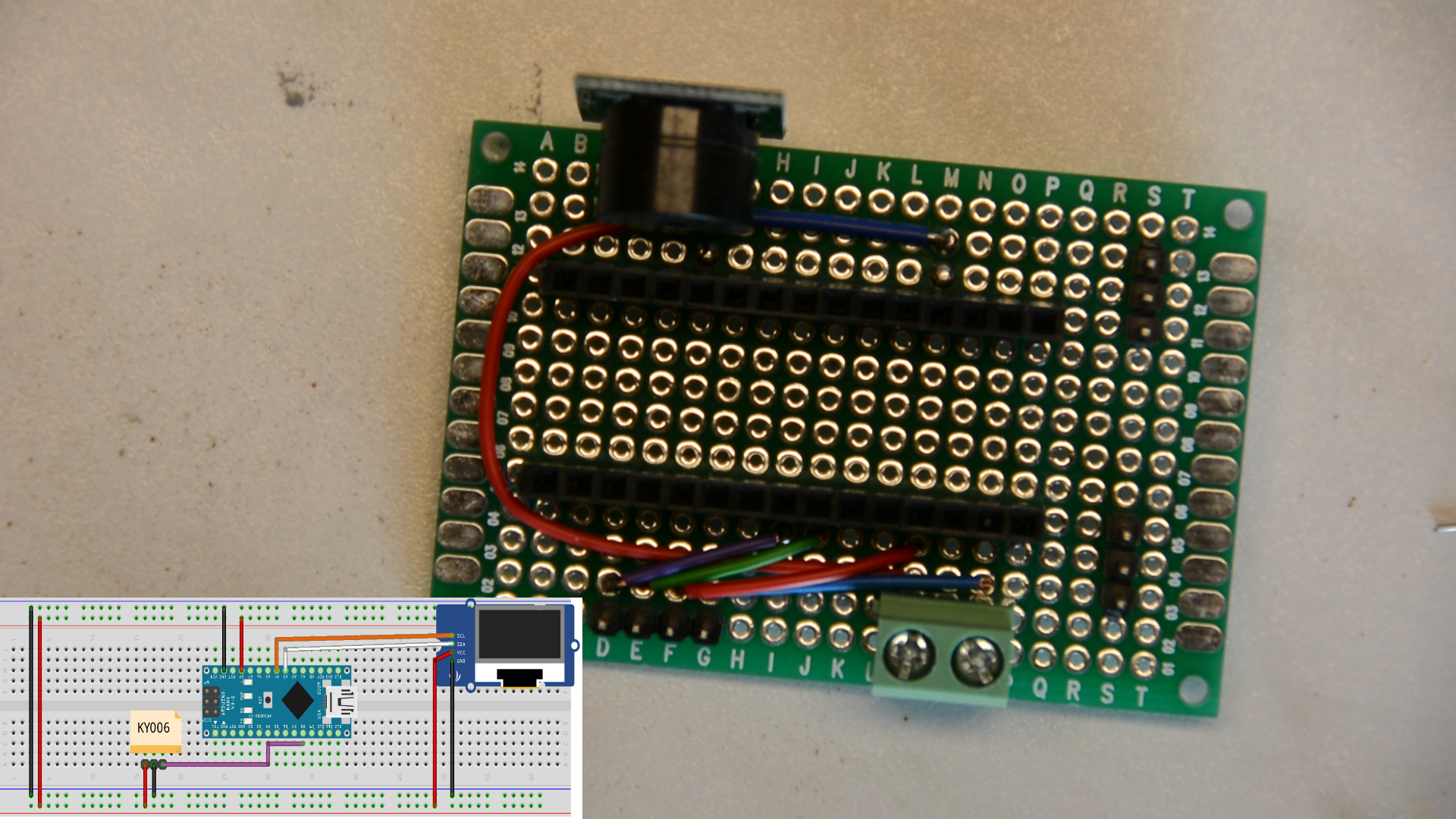
After the buzzer and the display we connect two more 3 pin connectors for the temperature sensor and the flow sensor.
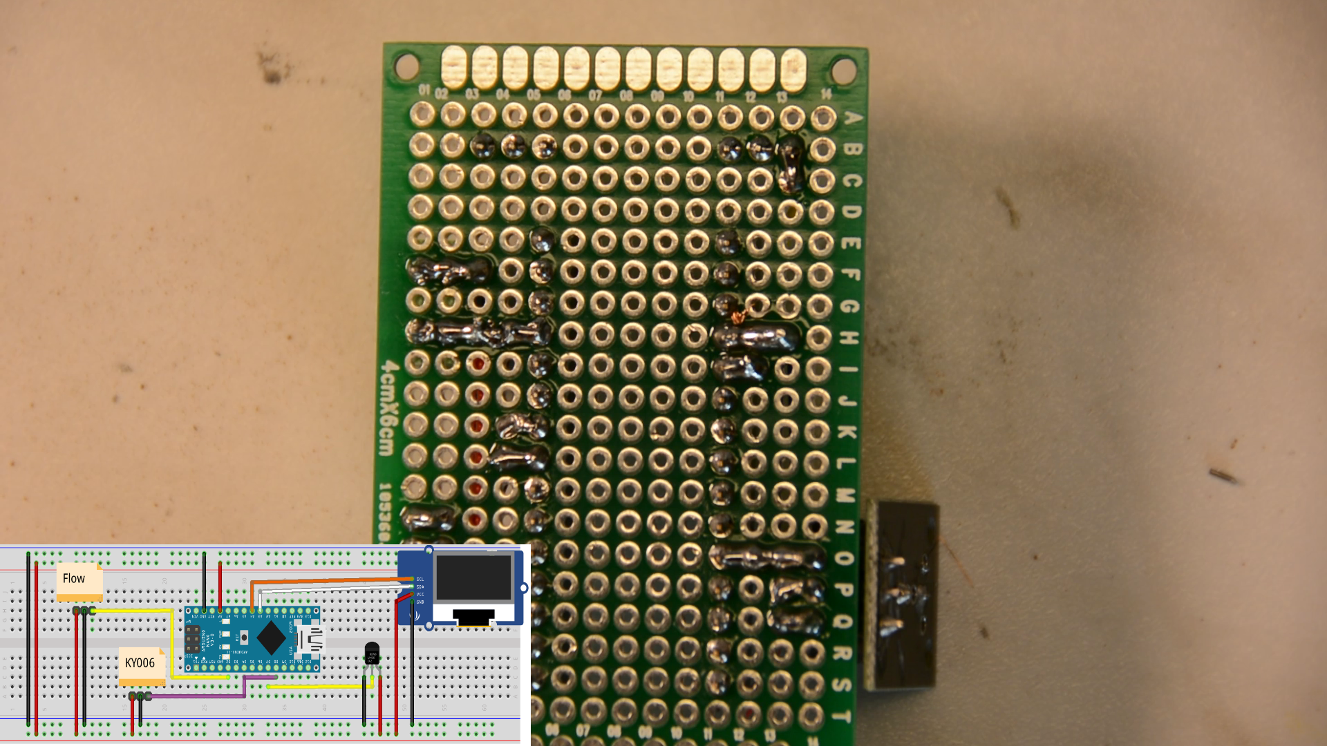
Now we add one last 220 Ohm resistor and can call it done.
The perf board gets a small 3d printed mount.

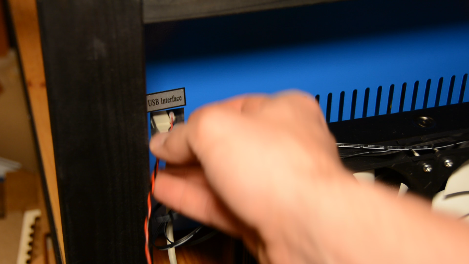
Installing the arduino to control the K40 cooling
The arduino can be connected directly to these two terminals that offer 5 volt.
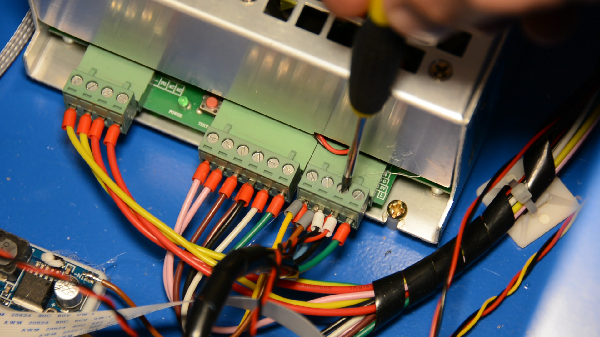
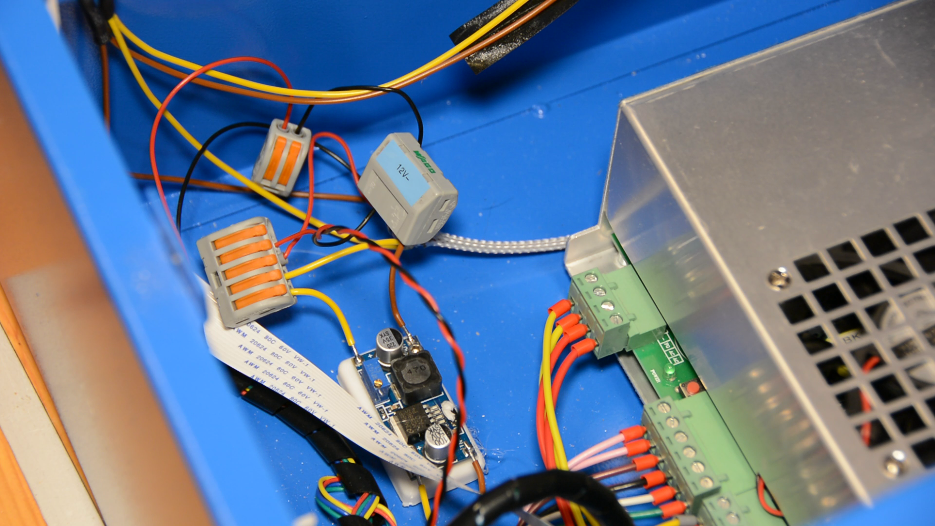
All the cables from the sensors are connected and the power supply is screwed in the terminal on the perfboard.
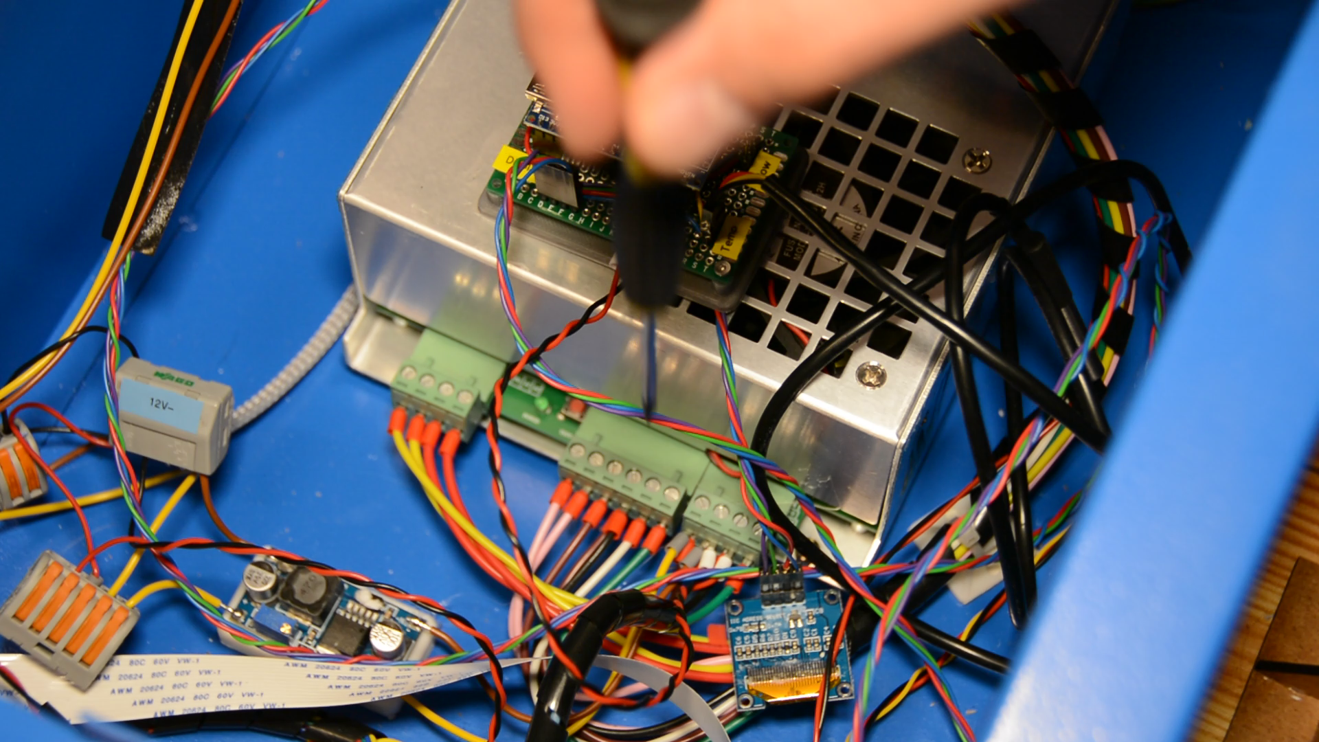
The arduino holder is secured with hotglue to the side of the laser.
We cut an opening in the panel with a Dremel tool.
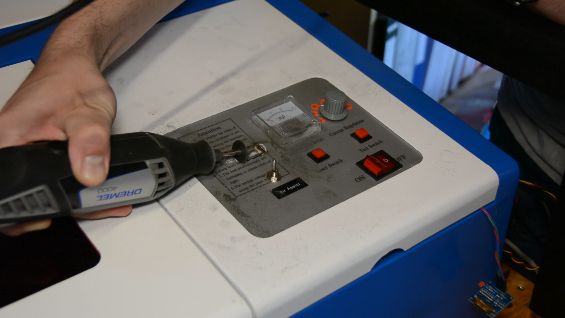
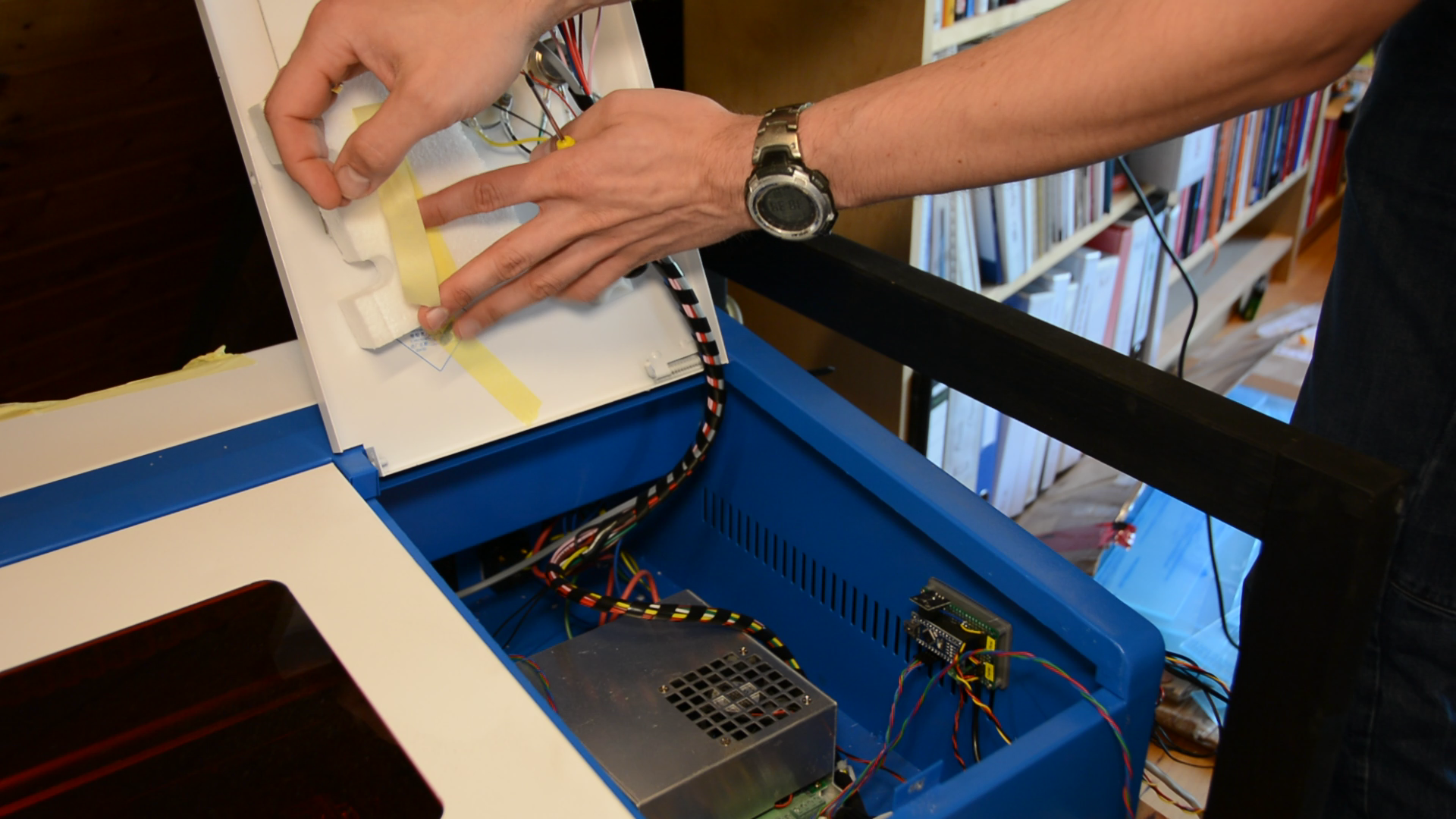
Before doing so we tape styrofoam to the back of the panel so that the metal shavings don’t get into the electronics.
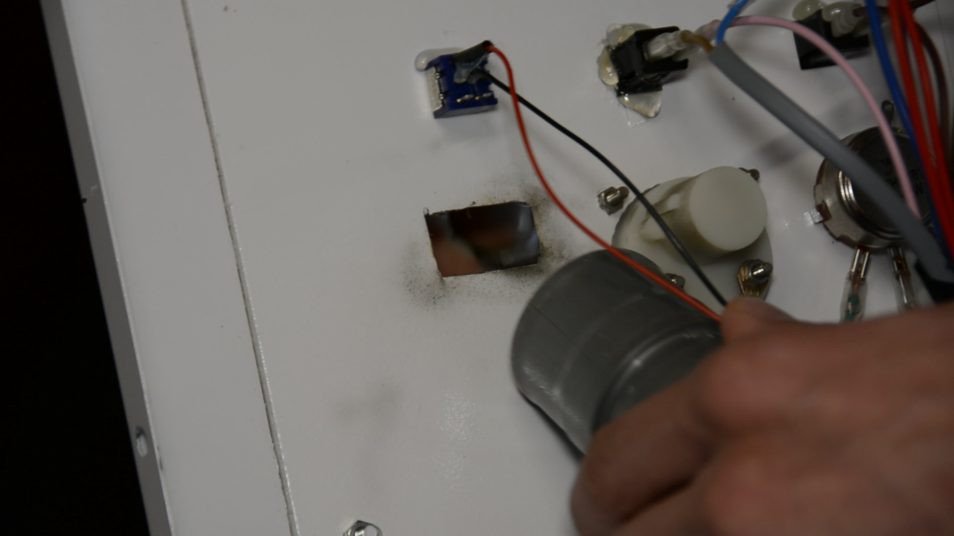
We carefully brake the edges of the opening with a file and then hotglue the panel in place.
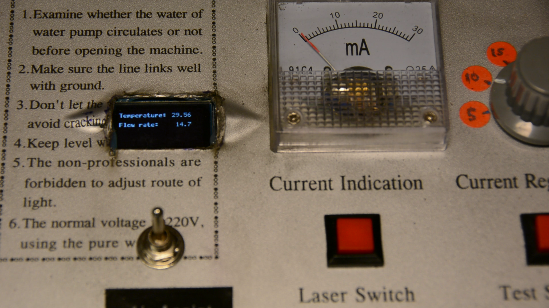
We can now monitor that the temperature is close to 20 degrees and that the water is flowing.
The cooling will allow us to use the laser over longer time periods.