
In this article we design 3dprinted mounting brackets to hold a power strip to the side of a workbench. We will also use this opportunity for a small tutorial in FreeCAD.
For the painting workbench we wanted to mount a powerstrip on the side. Let’s use that opportunity for a quick introduction in FreeCAD.
Before jumping into FreeCAD we take a few measurements of the power strip. It’s about 40 mm high and about 50 mm wide.

Designing the part
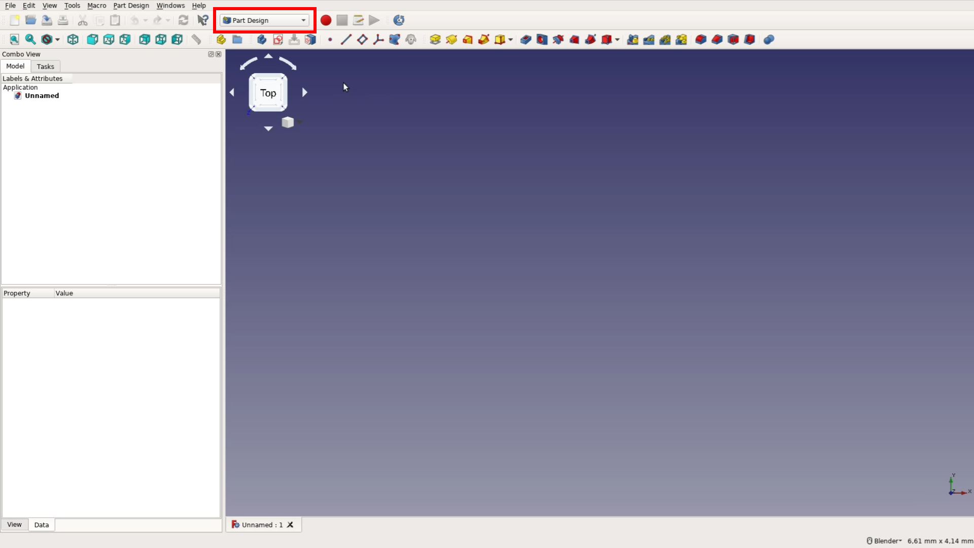
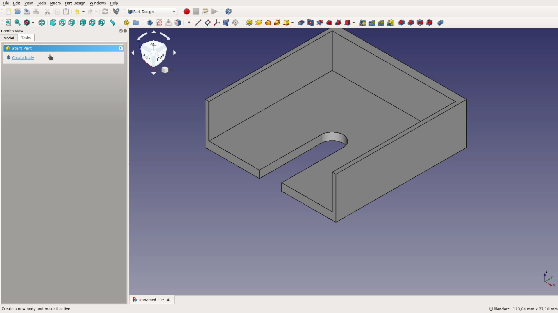
We start FreeCAD and in order to keep things simple we will work in this tutorial only with the part design workbench. Workbenches are similar to ribbons in Office or Fusion but also change the menu structure and the options FreeCAD offers you in the sidebar.
In the part design workbench we create a new sketch. The sketch should be aligned with the XY plane.
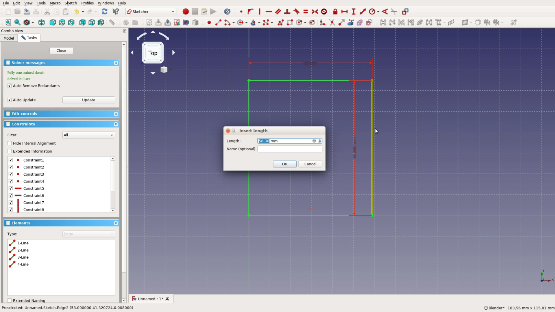
After selecting the rectangle tool we hover over the point in the center to start a rectangle. With the horizontal and the vertical measure tool we make the rectangle 53 mm wide and
60 mm high.
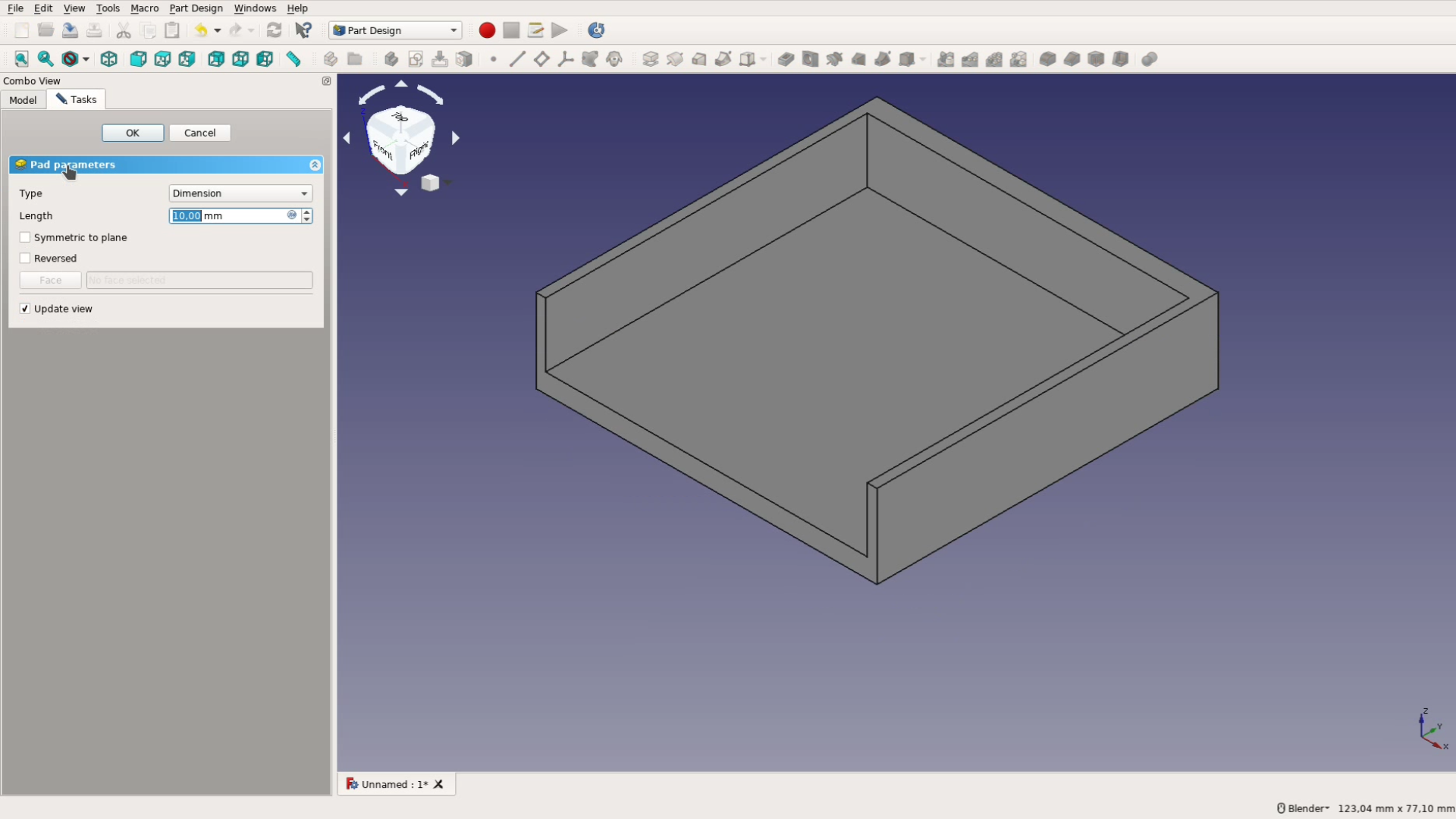
We then close the sketch and select pad from the task pane to create a plate with 3 mm thickness.

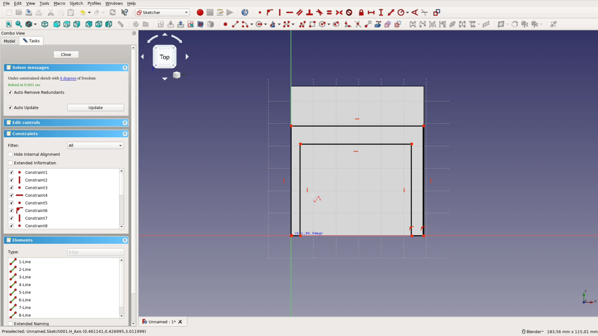
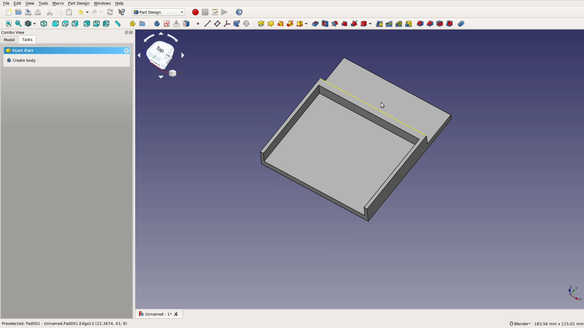
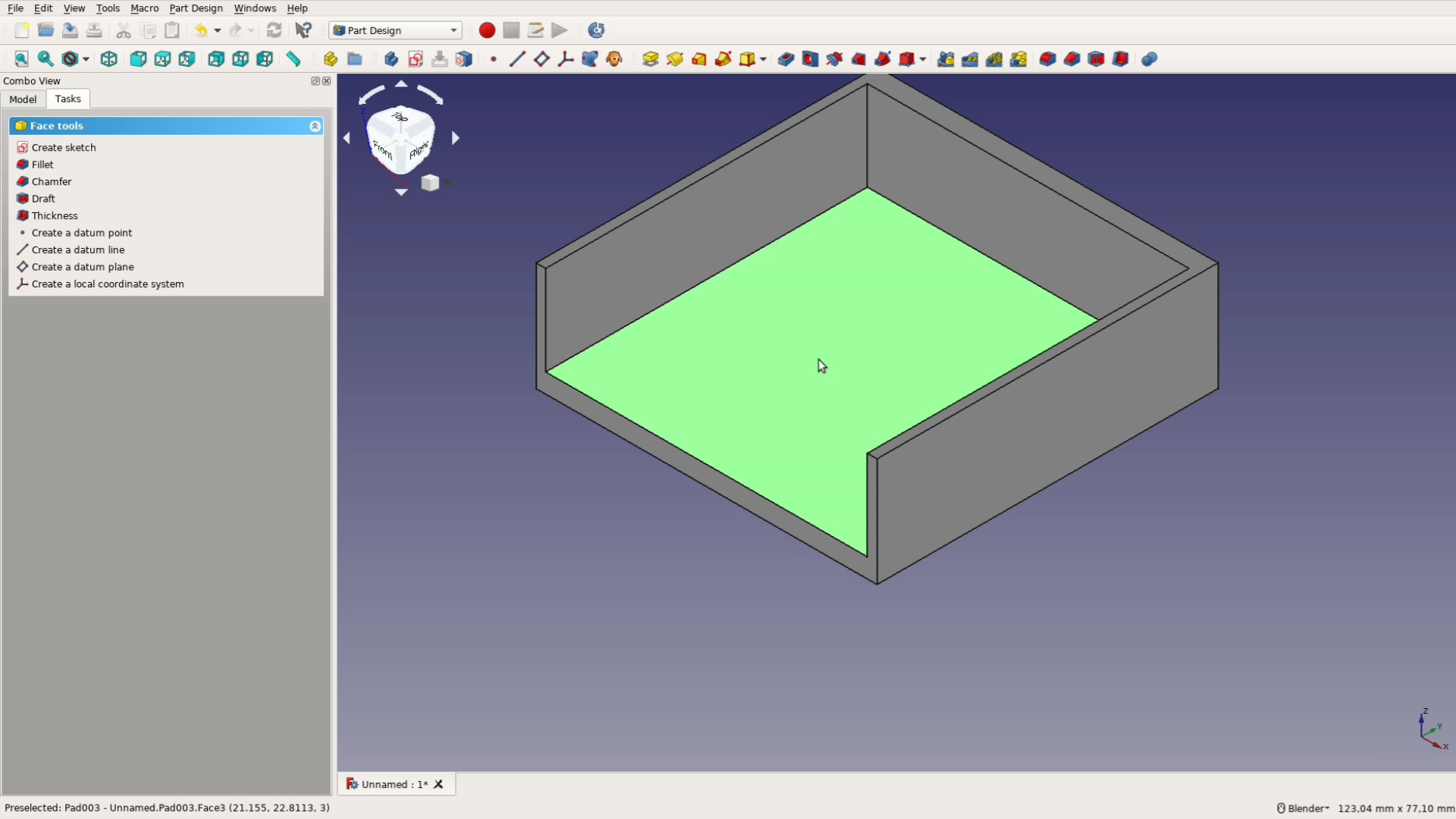
Next we go the task pane and create a sketch on one of the surfaces of the plane. With the multiline tool we trace the rough shape of the bracket.
FreeCAD will recognize horizontal and vertical lines if you draw them carefully and constraints the lines accordingly. It also creates constraints when you hover over a line or a point.
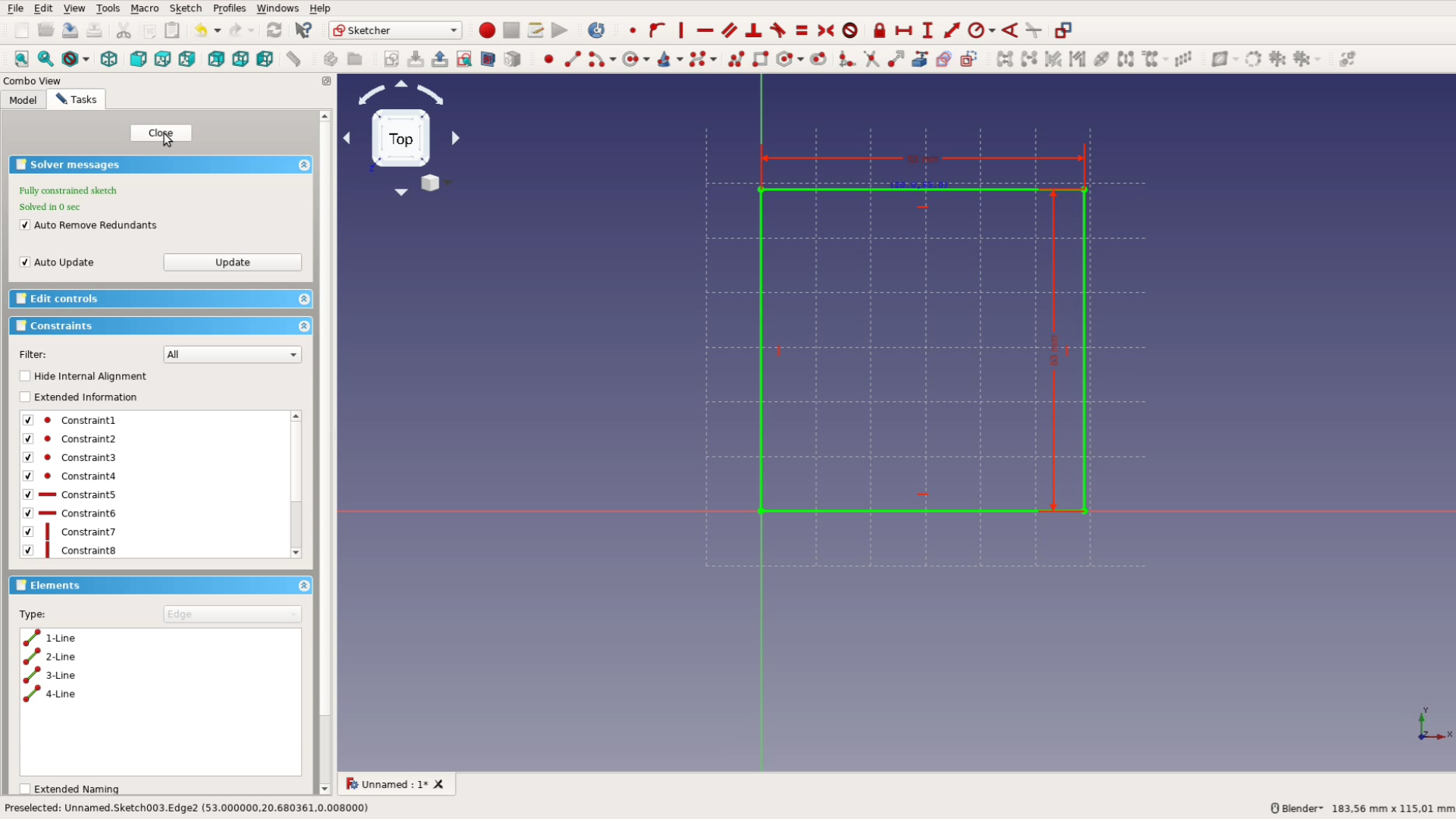
Next we add the constraints that it didn’t create automatically. Choose two dots and make them coincident or give a horizontal constraint to a line or two dots.
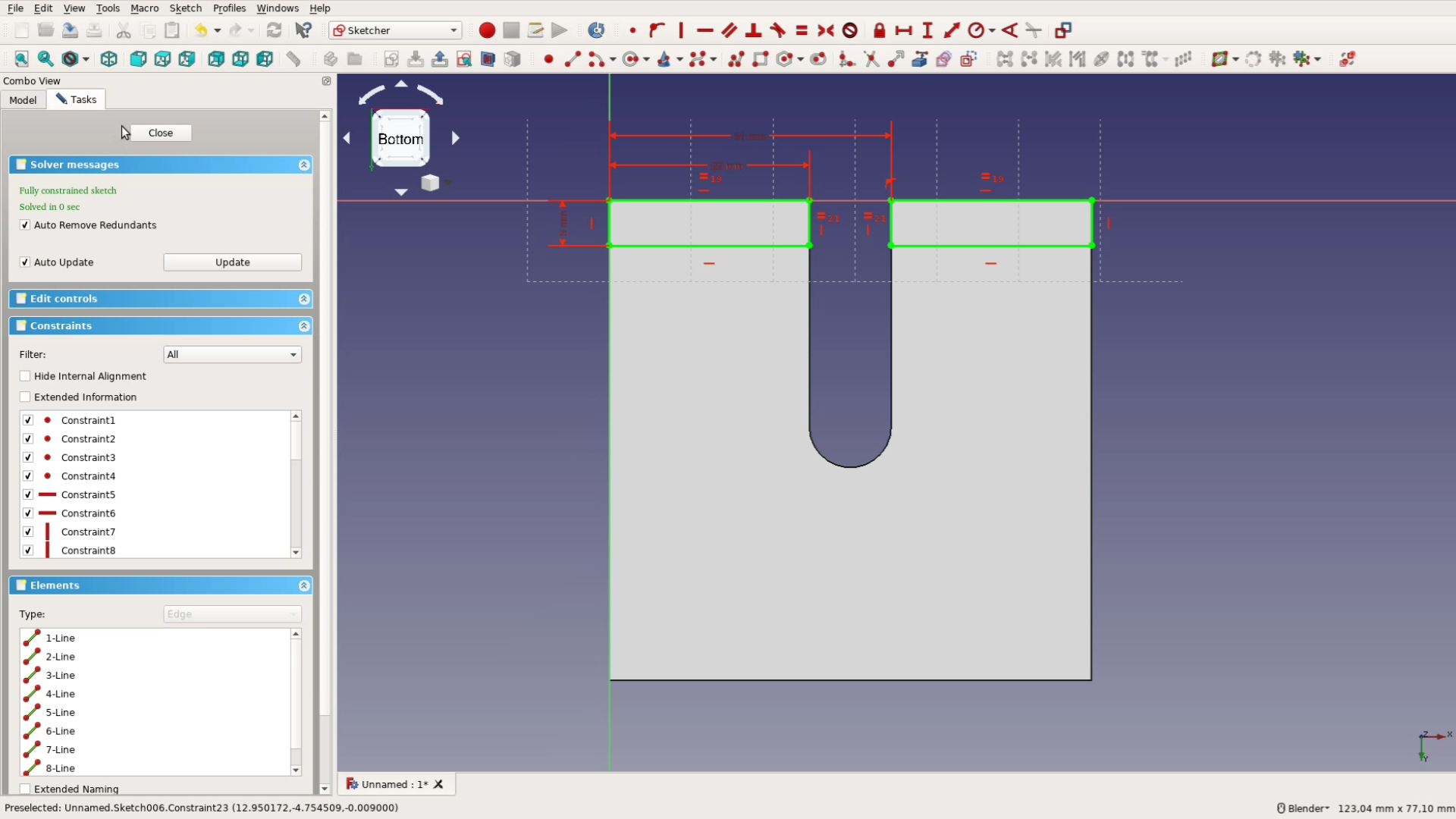
The thickness of the left and the right wall should be identical so we use the equal constraint before giving it a measurement of 1,5 mm. The height of the structure is 43 mm and the width 53 mm. When the drawing turns green it is fully constrained and we can close the sketch to pad the sketch by 5 mm.
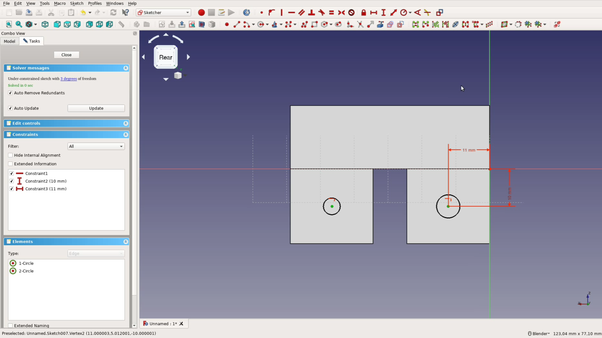
We make a third sketch on the backplate to indicate the mounting holes. These are just two circles that get both the same radius and are then positioned relative to the center of the coordinate system.
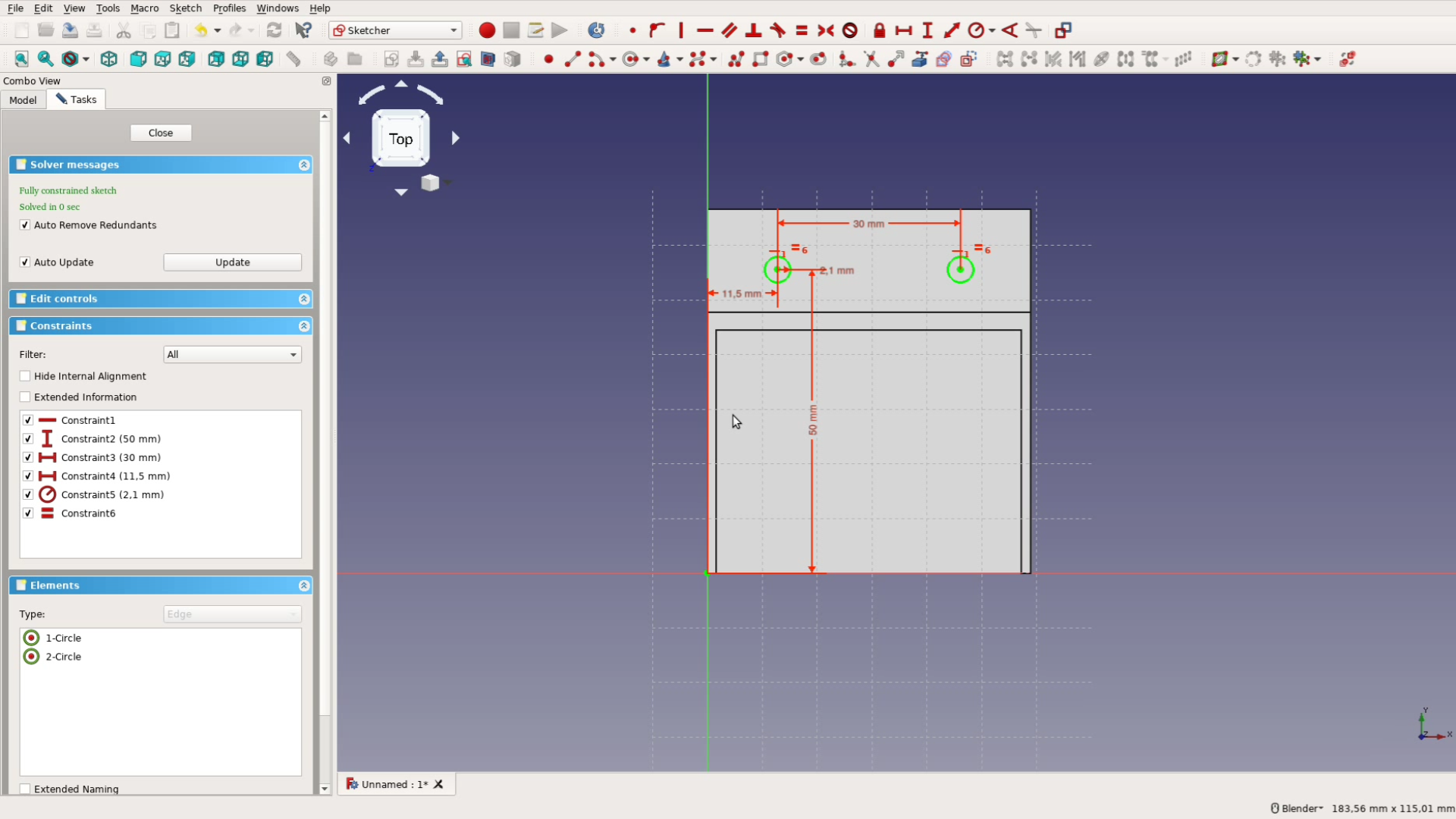
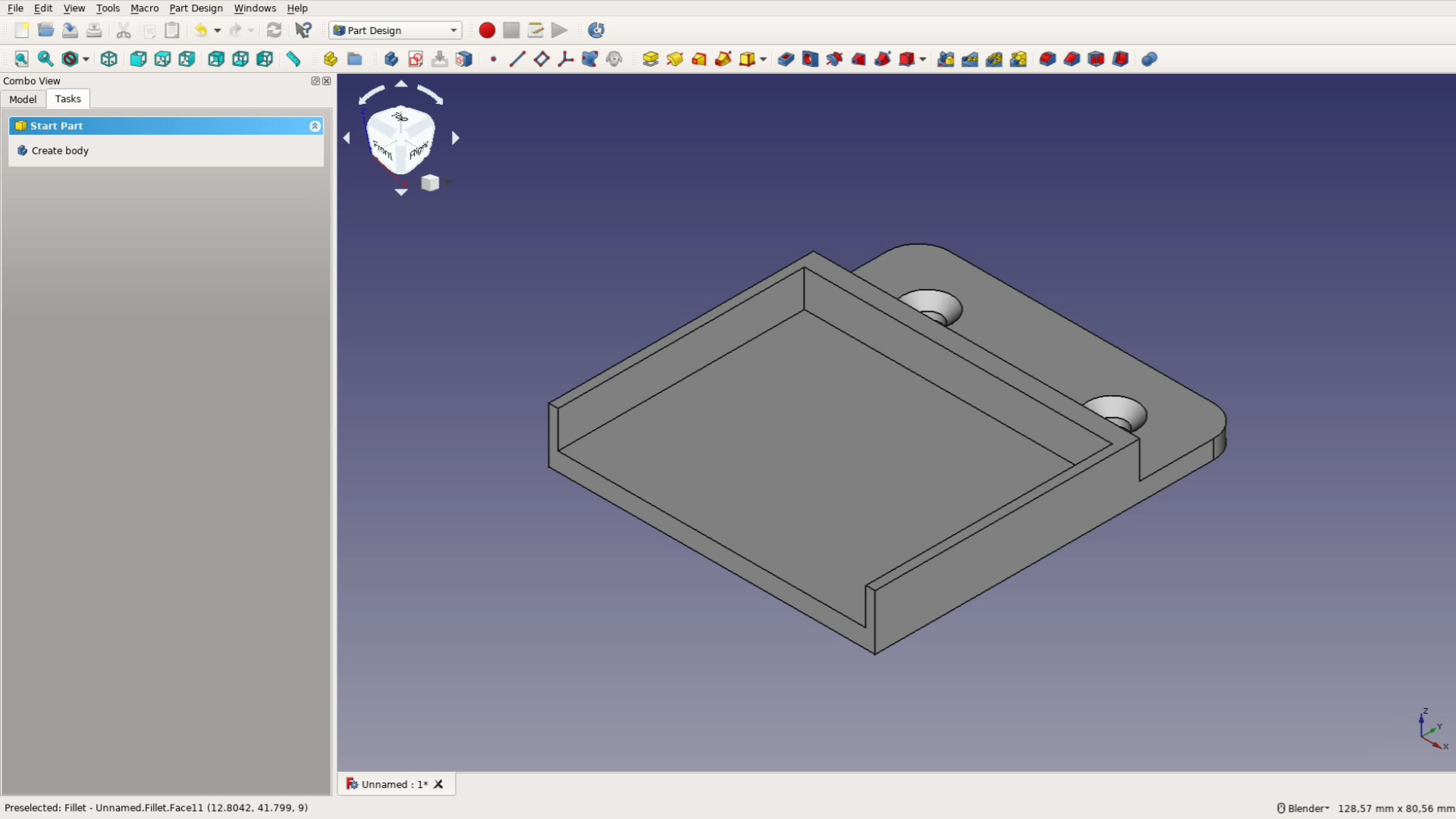
This sketch is then turned into holes by selecting the hole tool. M4 holes fit well with the wood screws we want to use and the tool creates nice countersink hole.

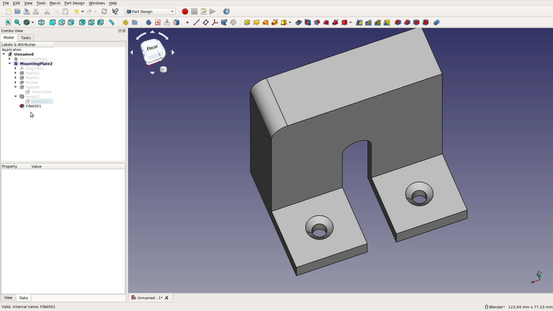
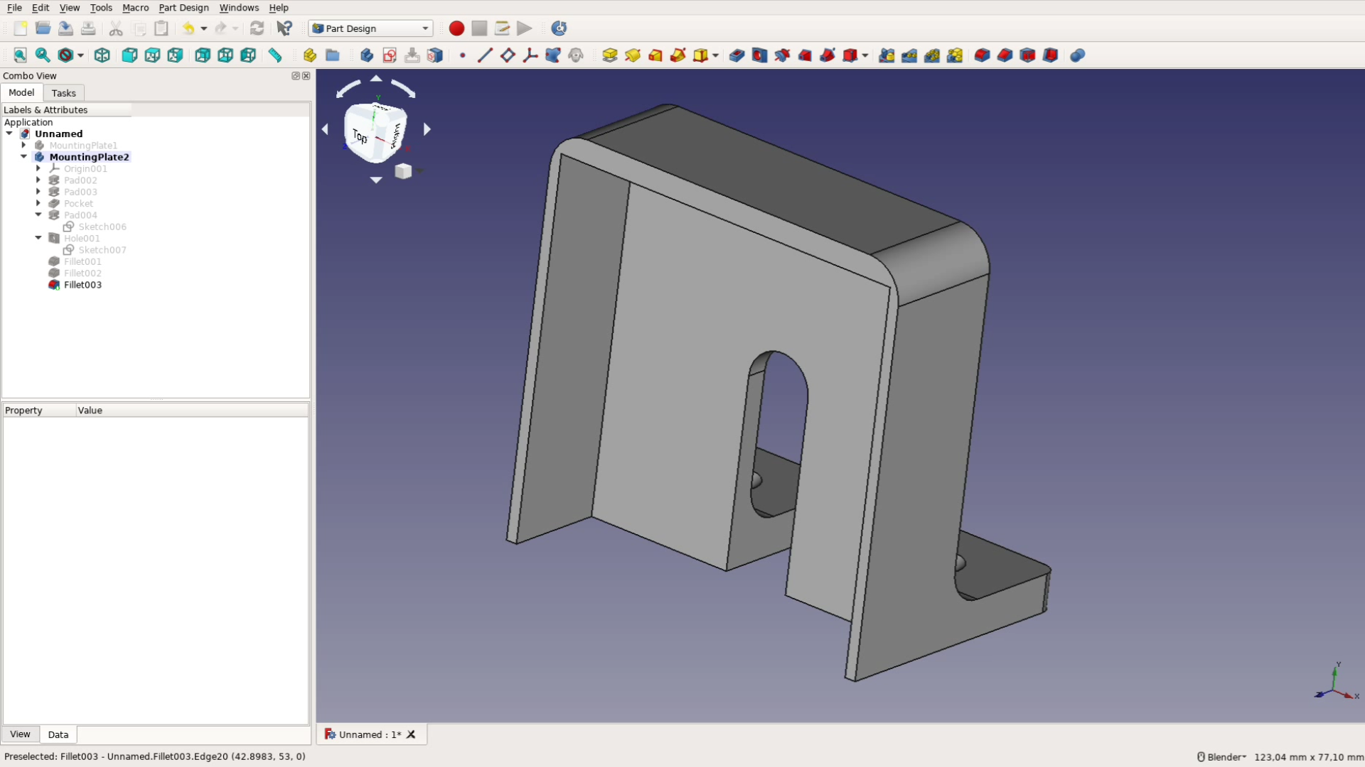
For a better look we select the two top edges and use the fillet tool to round over the corners. The first part is done and we can hide it by pressing space bar.
The other mounting bracket
Before creating a new sketch we first create a new body and then create a new sketch in the XY plane. The other bracket is designed in a similar fashion as the first one.
In the sketch we create a simple rectangle as before.
On top of this rectangle we draw – again as before – the bracket with the multiline tool.
In order to have a space for the power cord we create another sketch. In this sketch we create an arc, and connect it with lines to the base.
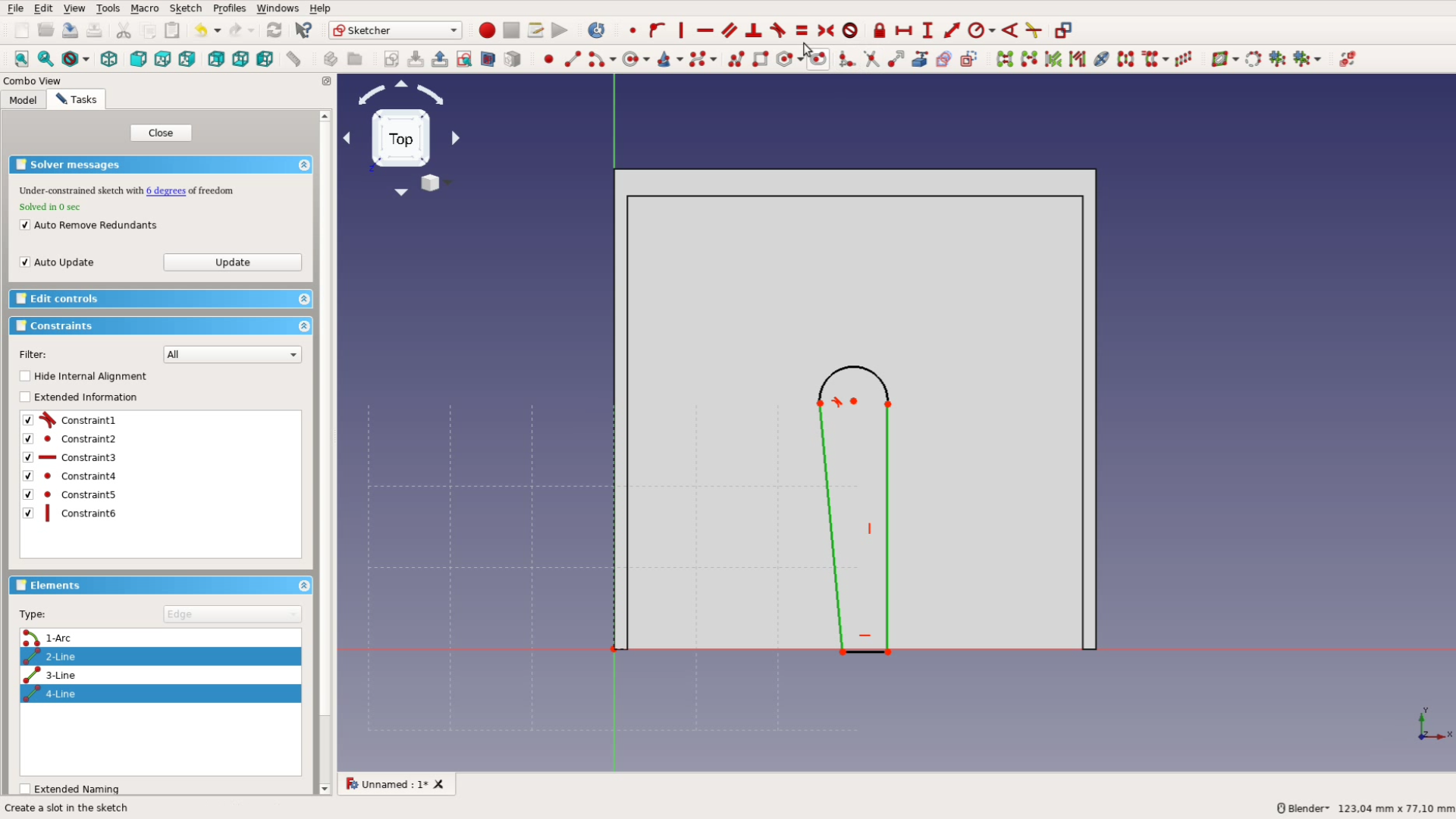
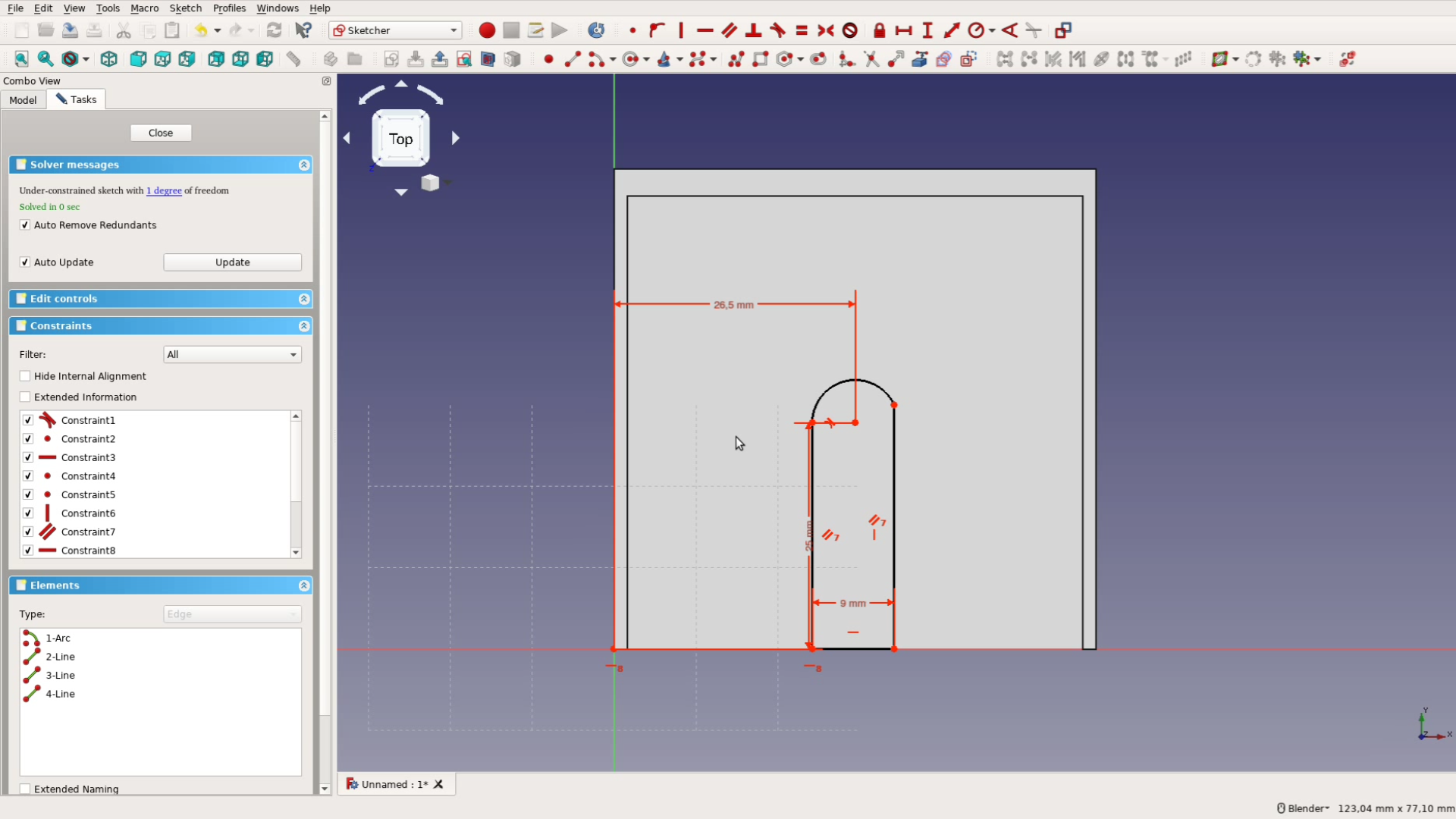
We make the two vertical lines parallel. The lower part should be horizontally aligned with the center and gets the respective constraint. We then apply some measurements. The width of the slot is 9 mm, the distance from the origin is half of 53 mm. FreeCAD accepts formulas for all input fields. The height of the mid-point of the slot is 25 mm.
The last thing to do in this sketch is to apply a tangential constraint for the two sides. This makes for a smooth transition between the straight line and the arc.
Now we close the sketch and use the Pocket tool to create a pocket through the entire body.
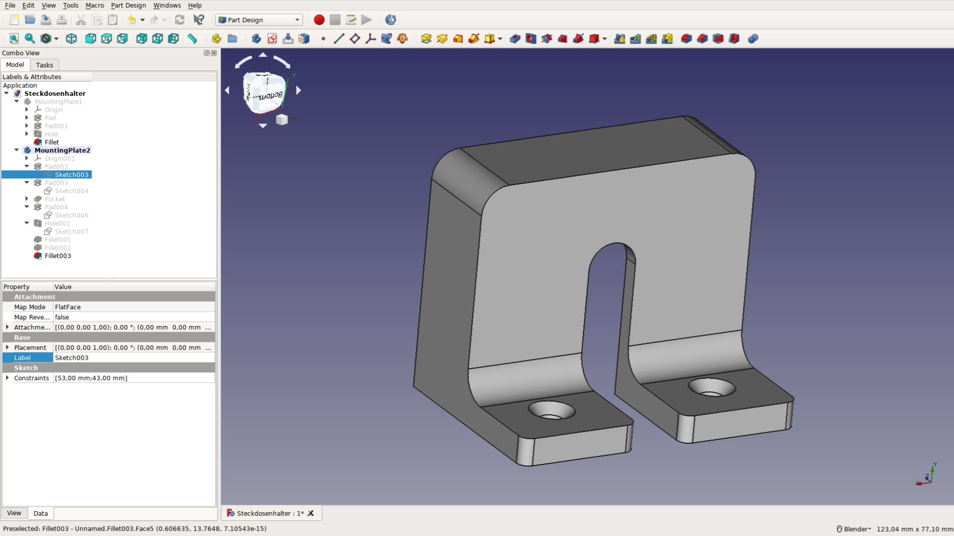
The last sketch consists of two squares that we will use to mount the bracket upright on the beam. We draw two rectangles and give them the right measurements in order to fit.
Again we can use formulas to position and size the parts.
We extrude the rectangles by 20 mm using the pad tool and then draw 2 circles on this new surface.
After positioning and sizing them we use these as before to create two countersink holes.
The last thing to do to this shape is to create some fillets. The top gets a roundover, as well as the outside corners next to the screws. To reinforce the structure a bit we also create fillets at the inside corners.
Both parts are done and we can export them as STL files, print them and try them out.
Fixing mistakes with parametric design
As it happens quite often a measurement was off and one of the parts is oversized for the power strip.
No problem – here come the magic of parametric models. We simply go back in the sketch with the bracket, adjust the size there, adjust the size of the very first rectangle and we have changed the part to fit.
After printing the modified version it fits like a glove.
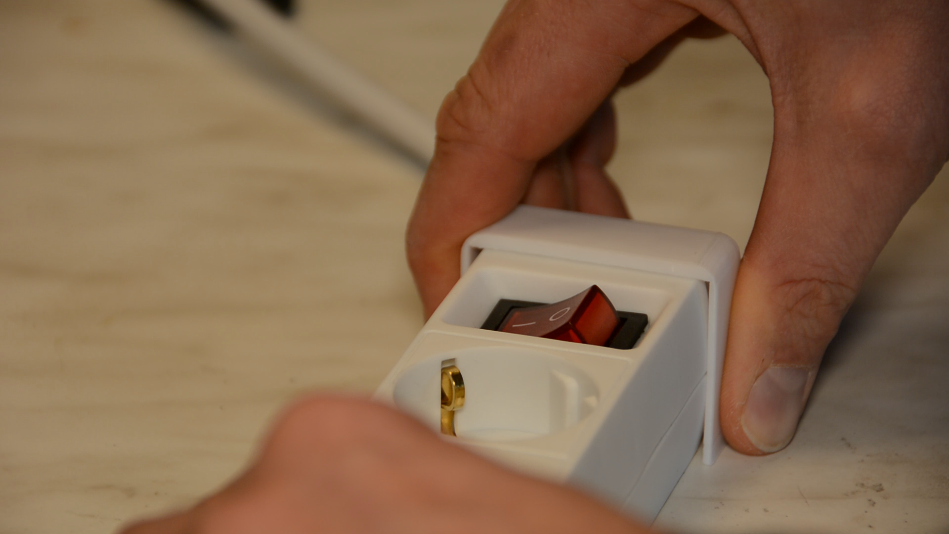
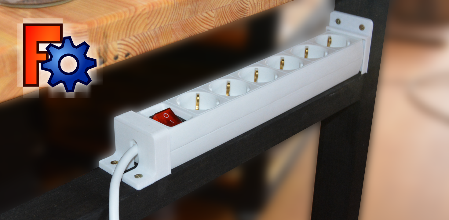
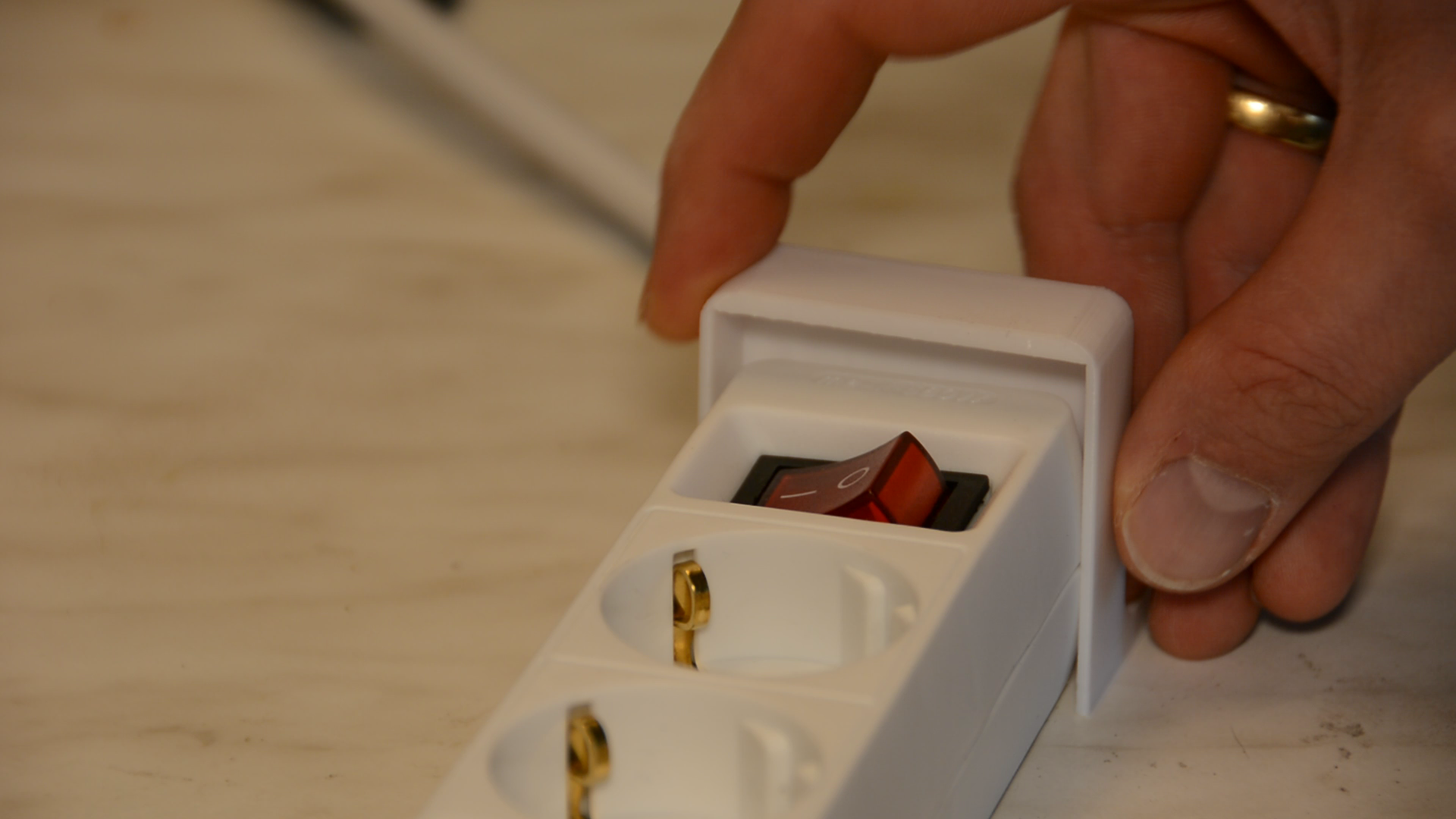
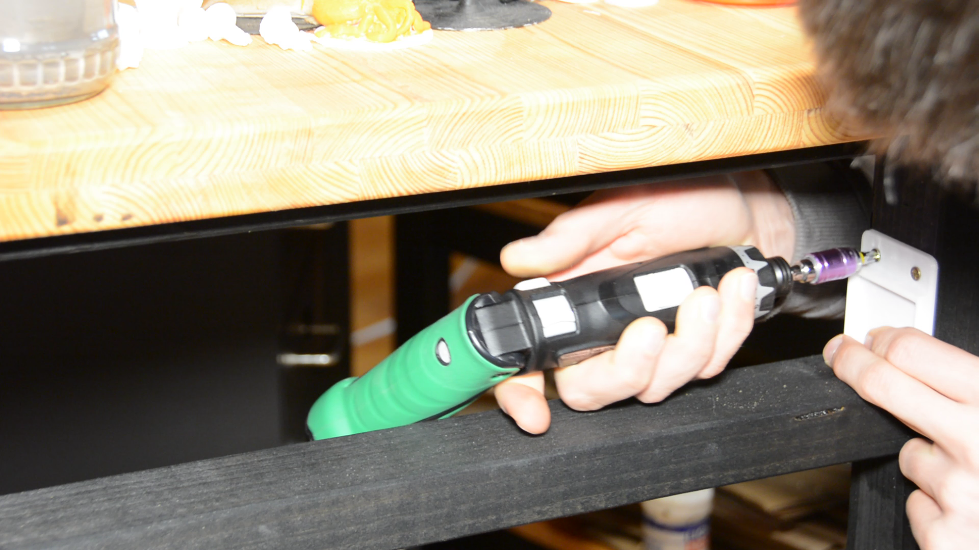
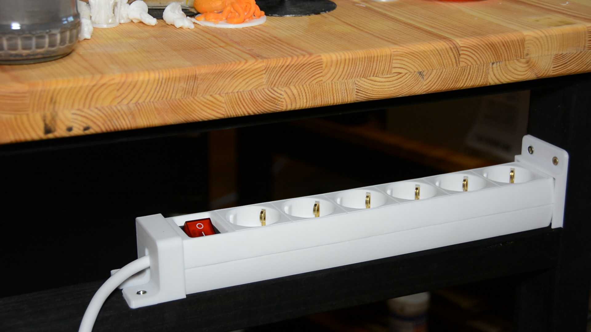
Installation
The brackets are installed and hold the power strip securely to the workbench.
I hope you enjoyed this little tutorial that shows some of the basic operations of FreeCAD.

This is a great inspiring article.I am pretty much pleased with your good work.You put really very helpful information. Keep it up. Keep blogging. Looking to reading your next post.
Vocal Remover Pro
Nitro PDF 2022
NetBalancer 2021
K7 Total Security
FreeCAD