
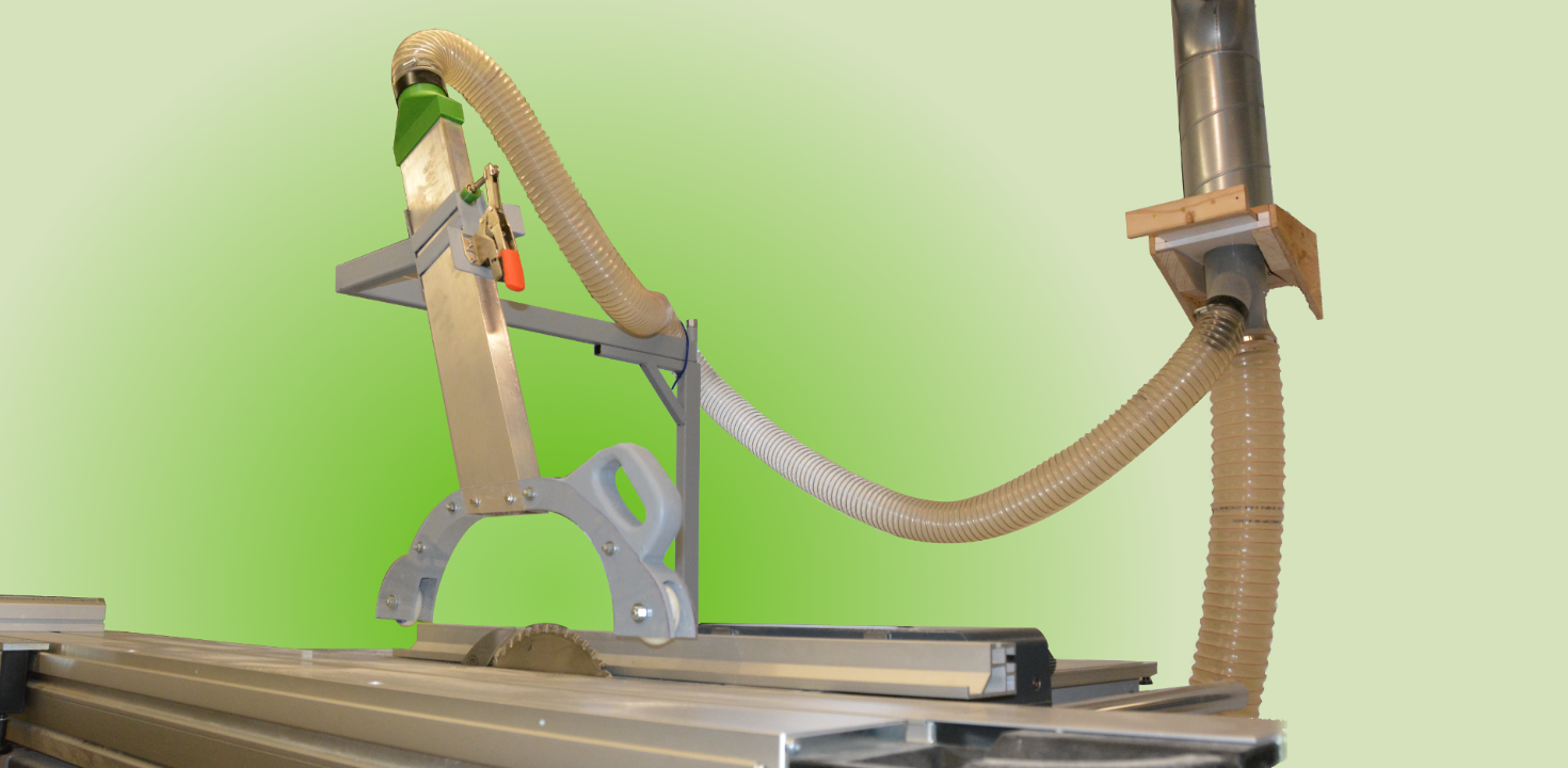
In this article I describe my build of a stable overhead guard with dust extraction for my felder table saw. The guard has a built in dust extraction and presses down the workpiece for extra safety. It can be adjusted in its height and easily moved out of the way when it’s not needed.
The guard and dust extraction on my table saw is attached to the riving knife which makes hidden cuts quite cumbersome. The manufacturer of my table saw offers an overhead guard – however it costs nearly 1000 EUR – which is a good motivation to build it on my own.
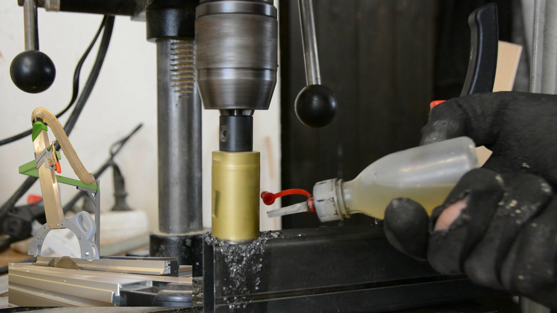
My building process starts with a thick flat steel bar. I drilled holes for 2 M16 bolts so that I can attach the steel bar to the tablesaw.
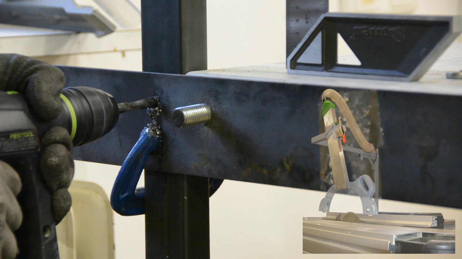
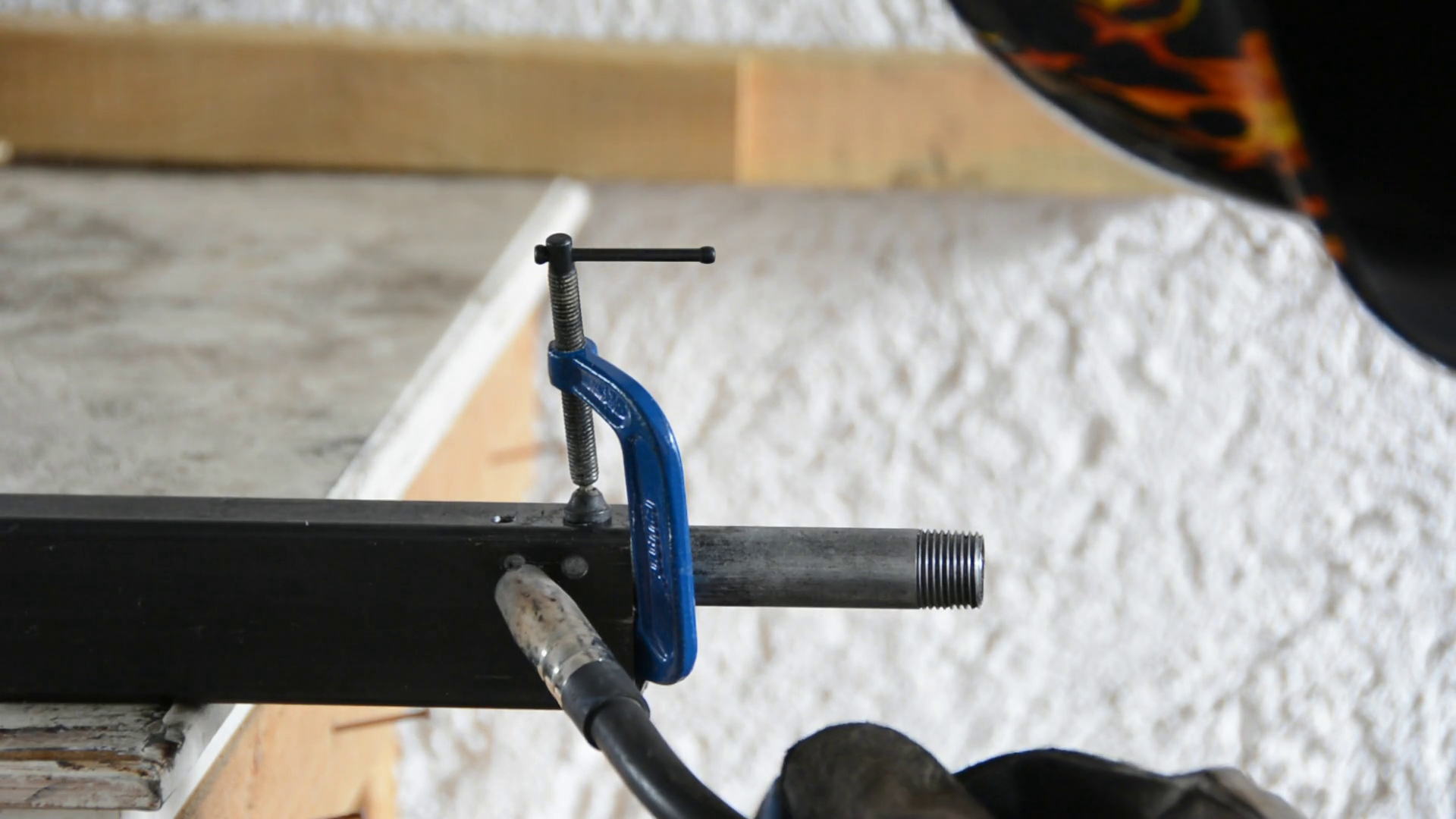
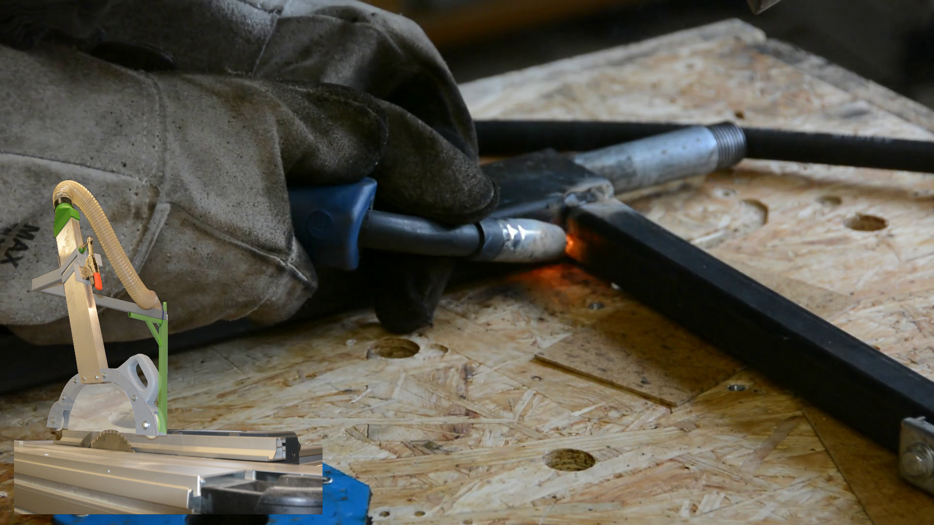
This steel will hold an upright square steel tube to hold the guard over the table. At the upper end of this bar I drill a few holes so that I can plug weld a thin steel pipe to the inside of the tube. This will later act as an axle to swing the guard out of the way. Next to the pipe I weld a support at 90 degrees which itself is supported by a cross brace.
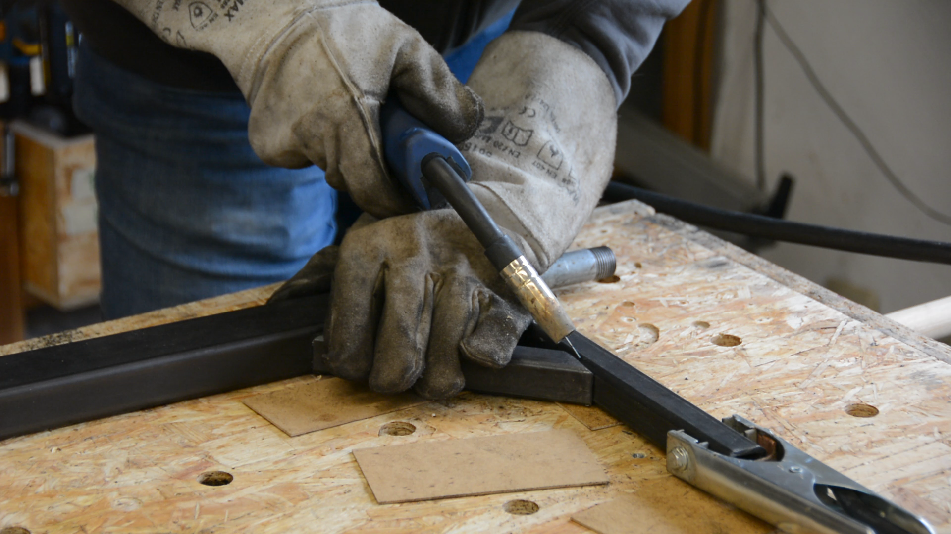
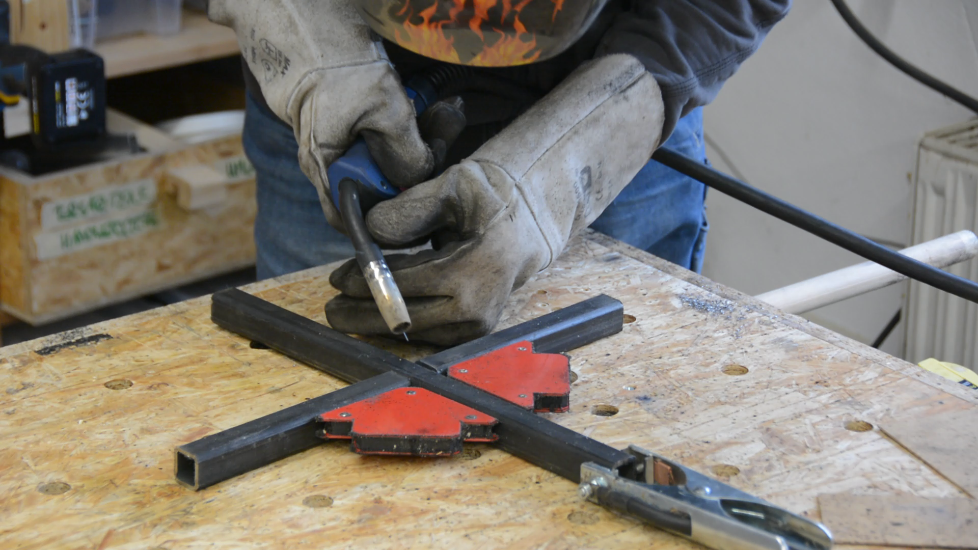
The bottom of this upright tube will get a cross of 30 millimeter square tubing attached with a few welds. This way the flat bar will not have to bear all the shear forces from the arm and I can adjust the stand for the unevenness of my shop floor.
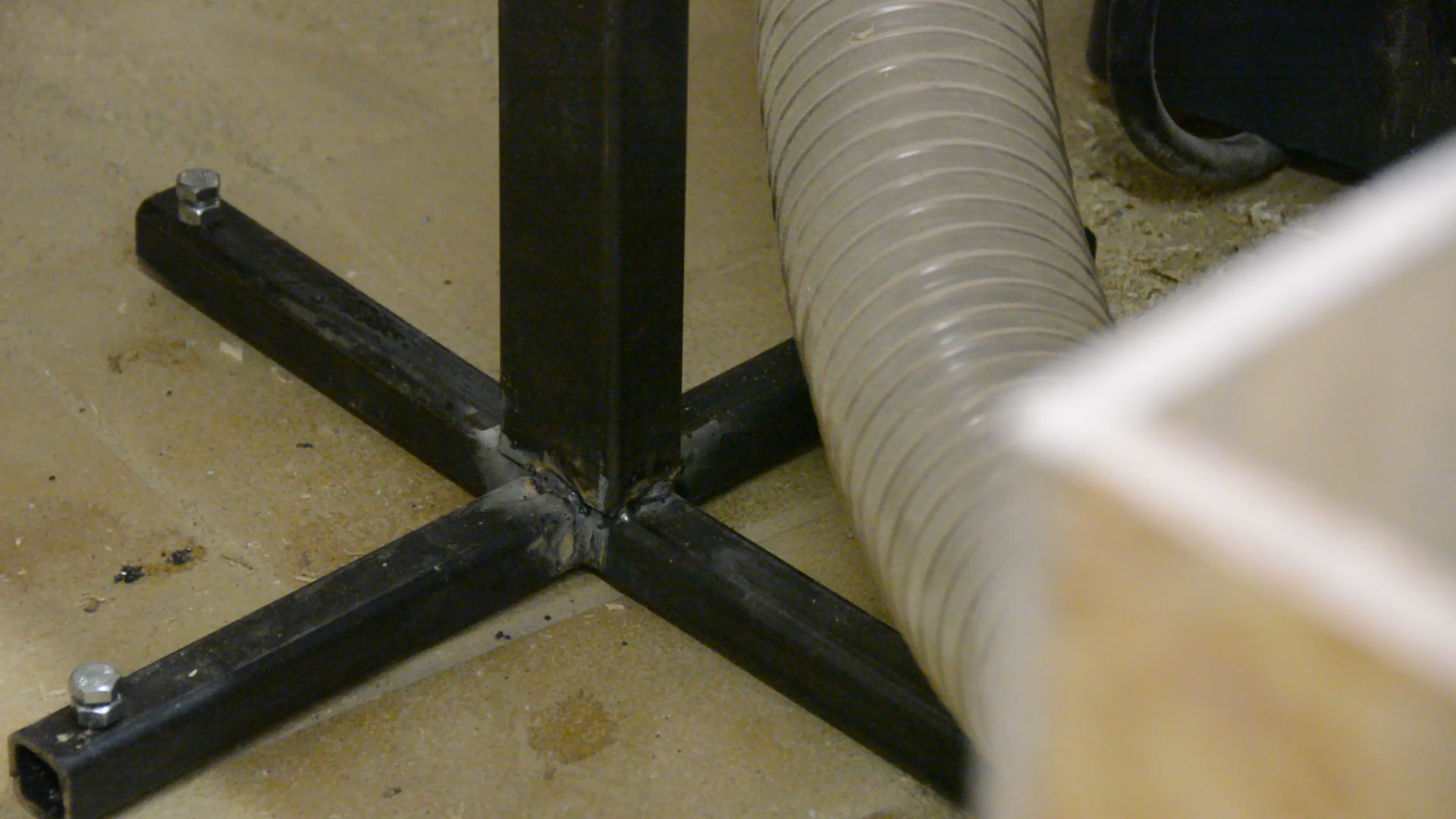
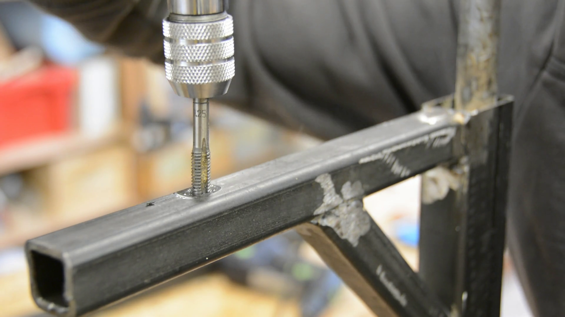
For the adjustable feet I drill a hole at the end of each part of the cross. The lower hole gets tapped with a M8 tap while I open the upper hole to 10 millimeters. With a few machine screws I can compensate for my uneven shop floor and any warping due to my poor welding skills.
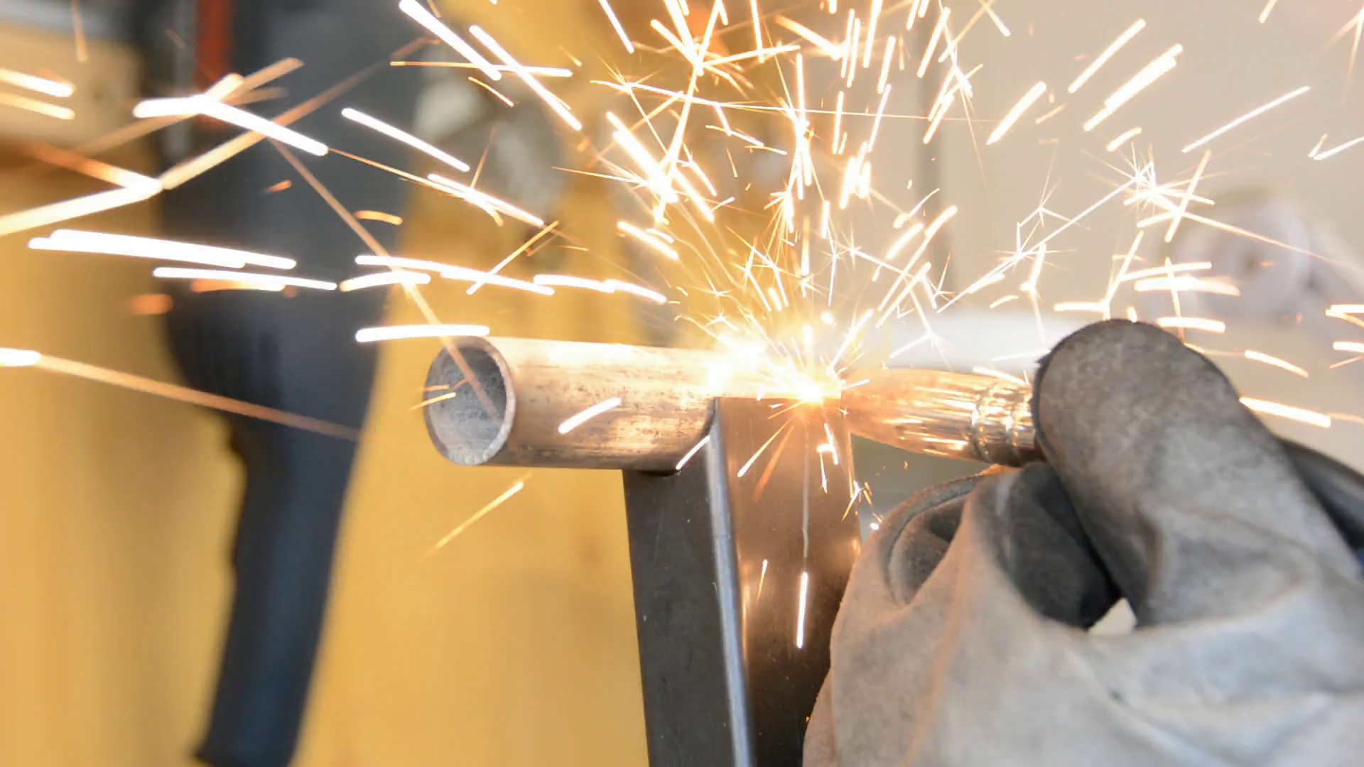
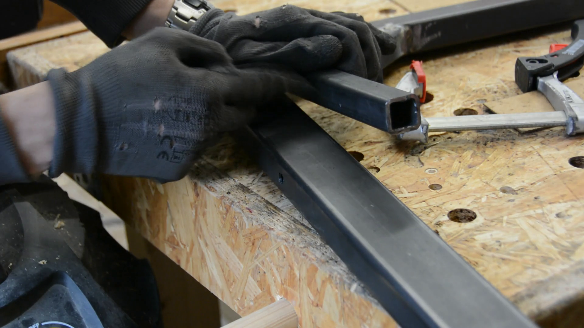
Building the arm itself is relatively straight forward. I drill a hole in the end of a steel tube. Next I fit a steel pipe in that hole with an inner diameter slightly larger than the outer diameter of the first pipe and weld it in place. With another piece of tubing welded at a 90 degree angle to the first one the arm can be testfitted.

While holding the arm 90 degree to the upright post I drill a 8mm hole through the arm and start drilling into the support. Using this mark as a starting point I drill and tap a M8 hole and screw the arm with a handknob to the support.
To help me decide where to put the guard itself I start sketching its structure on a piece of wood and mock up the position of the aluminum tube that will serve as the dust extraction.
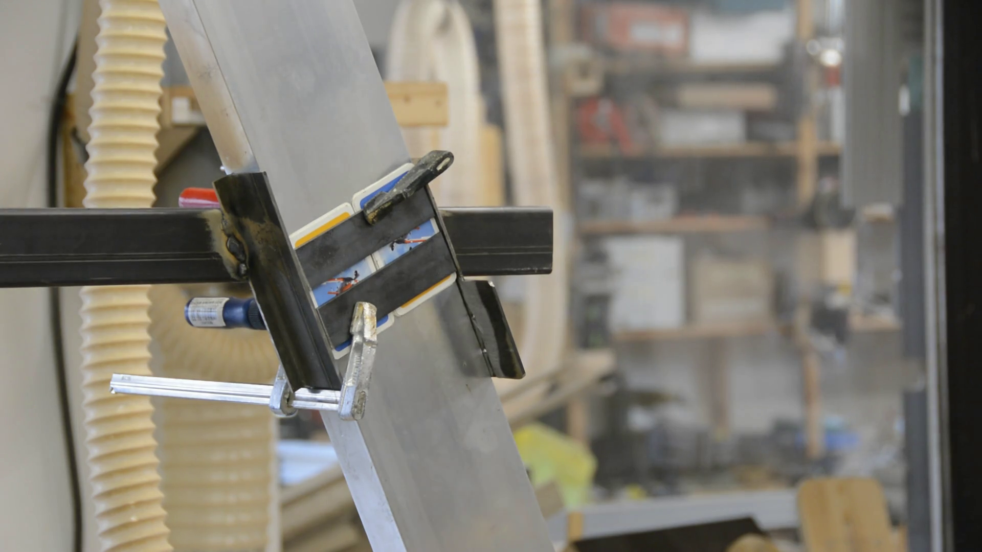
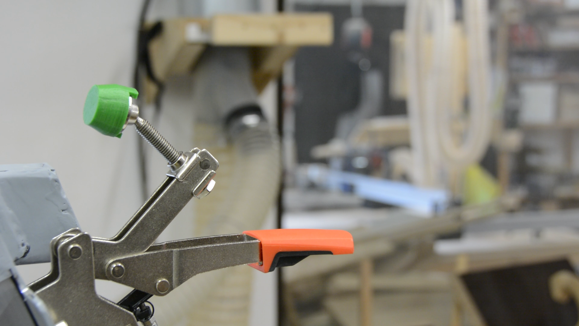
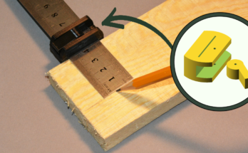
Ensuring the right amount of play with a few shims I weld a channel to hold the aluminum tube to the overhead arm. By drilling a few holes in the front plate of the channel I can mout a a toggle clamp to hold the tube in place and and allow for an easy height adjustment. As the toggle clamp is not designed to clamp pieces lower than the mounting surface I print an alternative cap on my 3dprinter.
With the aluminium tube cut to length and clamped in place I can start working on the actual guard.
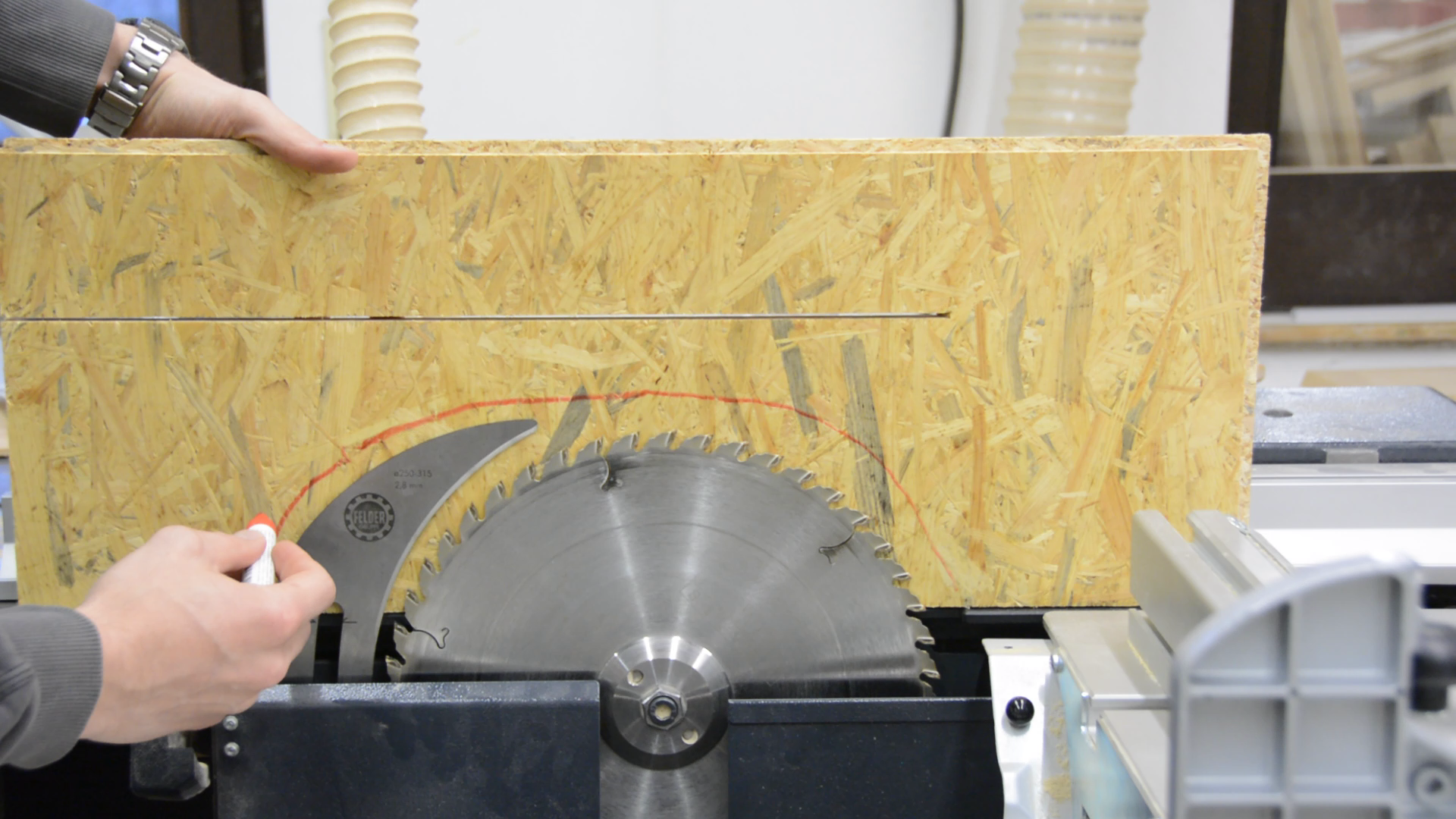
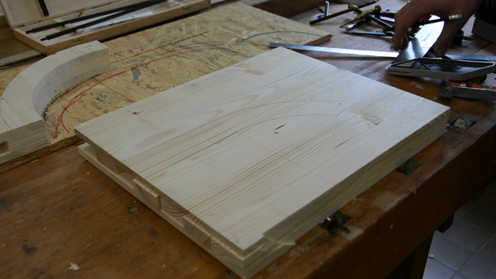
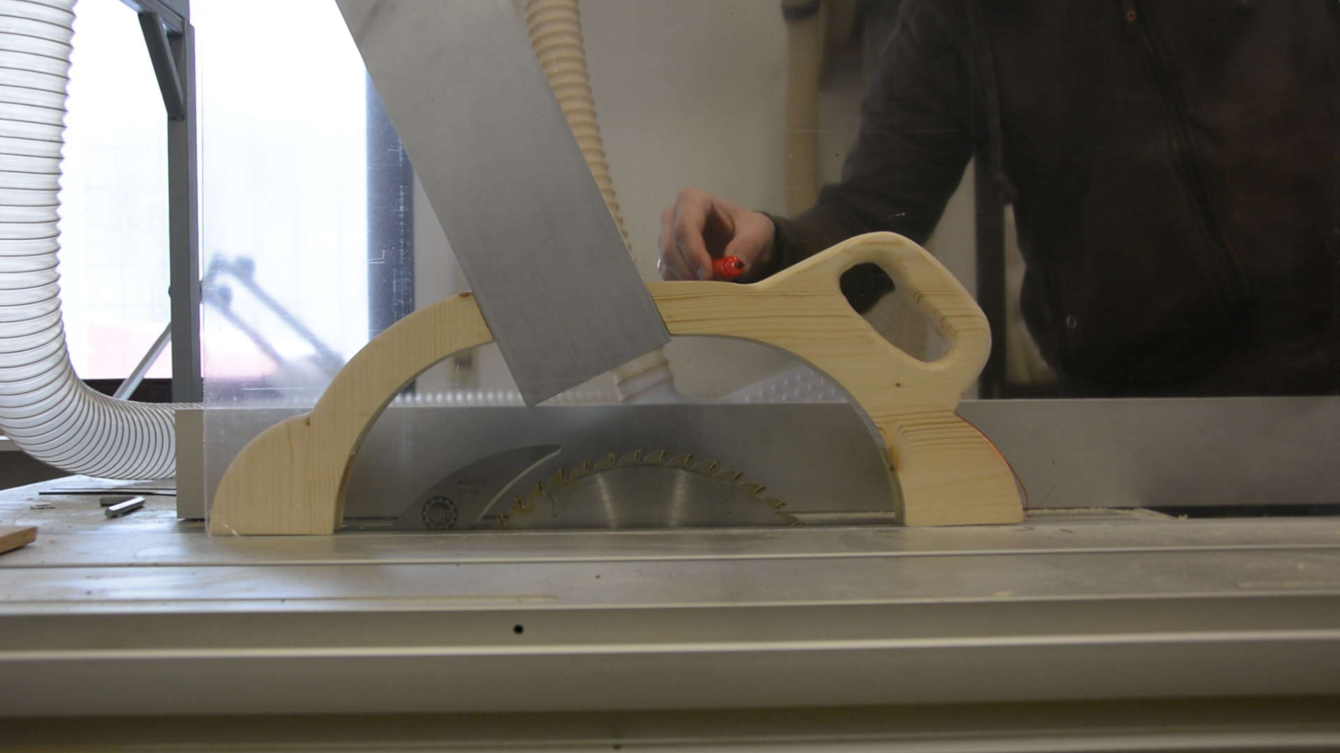
For the guard I glue pine scrap pieces together. Their size is a bit bigger than the parts I need for the guard. After the glue is dried I use my highly professional sketch of the table saw blade to sketch the rough shape of the guard. For the handle I trace the handle of saw. I cut the wooden pieces on the bandsaw.
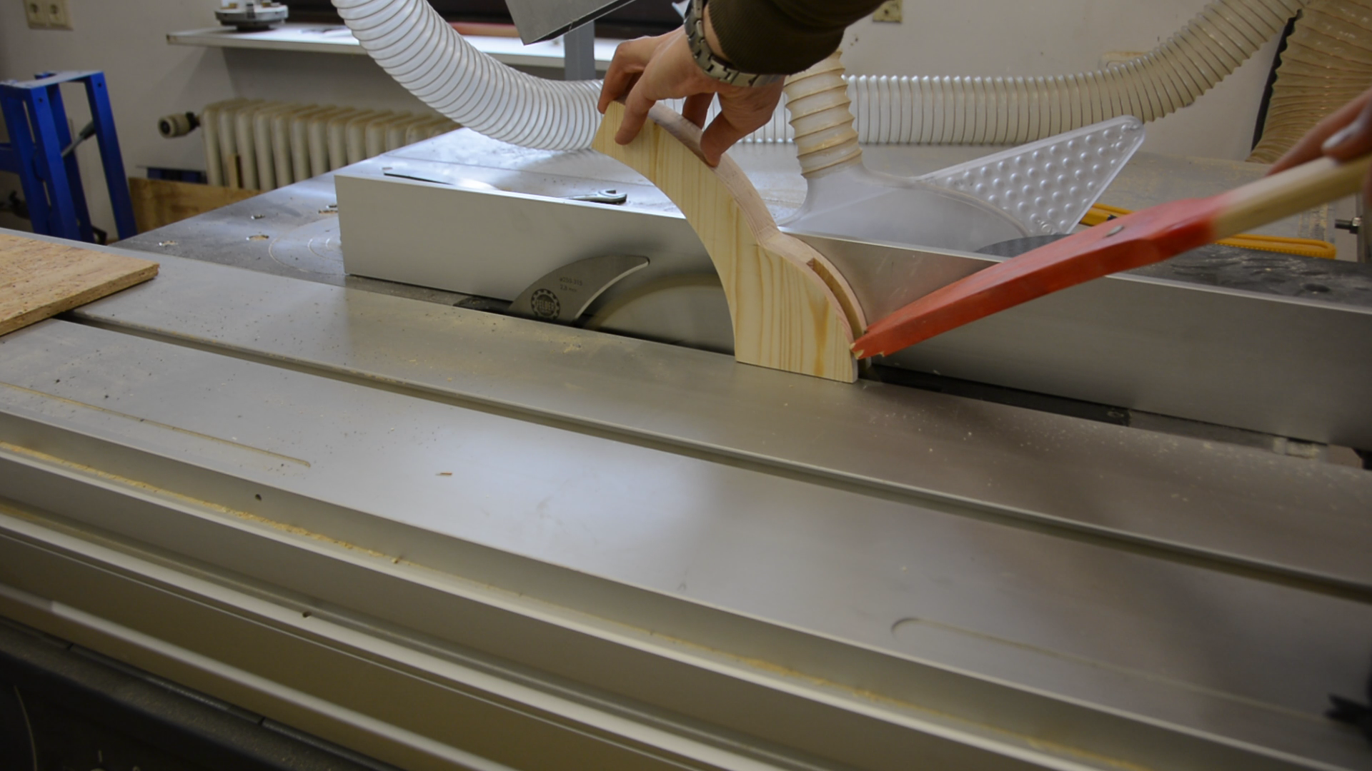
On the table saw I remove the middle piece of wood to make place for two inliner wheels that will help to press the workpiece against the table.
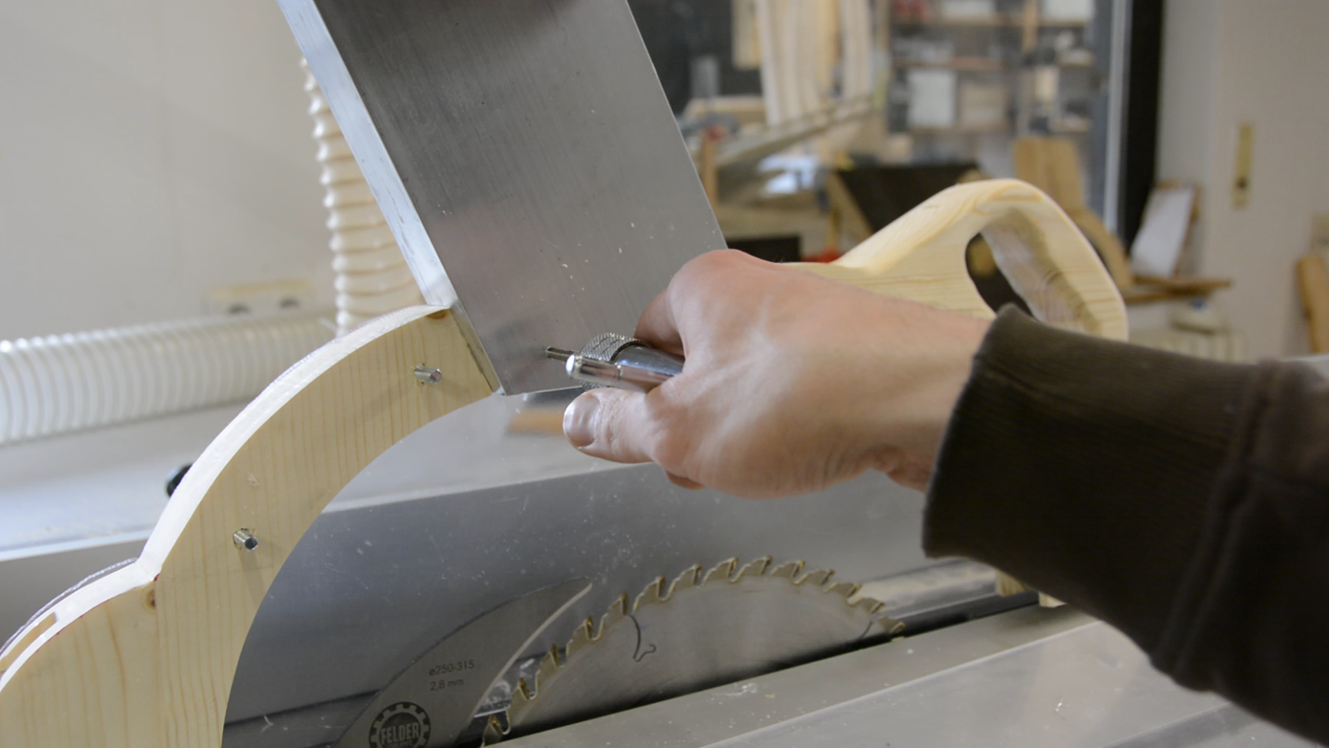
While putting the pieces next to the aluminium tube I trace the shape to a sheet of acrylic and cut it out on the bandsaw. Next I put again everything in place and mark holes for bolts that hold the guard together. The aluminum tube is cut to shape and gets a few M5 holes in order to connect the guard and the tube.
Lastly I use my 3D printer to print an adapter that fits at the end of the aluminum tube and connect to a 80 mm hose. After a bit of sanding and some paint the build is done.
Let me tell you about the features of the arm. Especially for thin stock the wheels help to hold workpieces to the table.

The height is easy to adjust with the toggle clamp and the guard can be moved out of the way for hidden cuts.
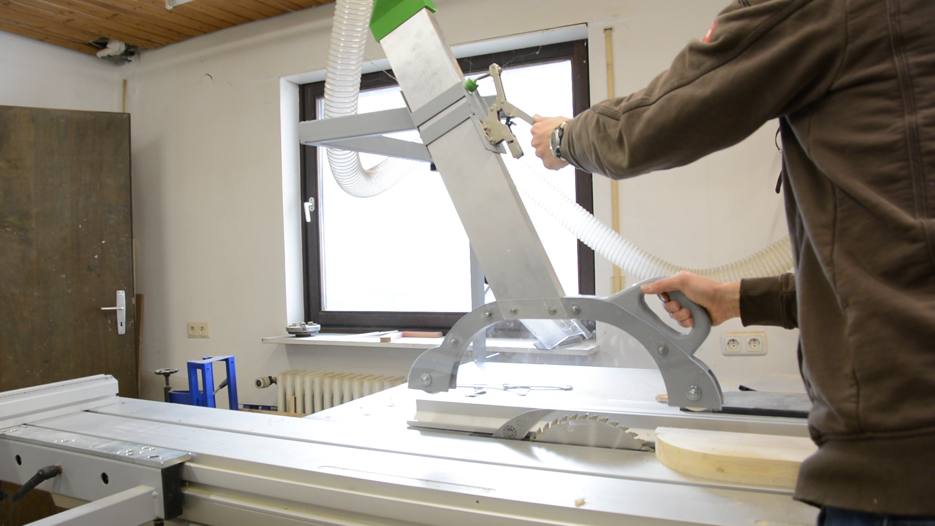
As the tablesaw is actually a combination of a table saw and a shaper the swinging arm makes it easy to move the guard out of the way when I want to use the shaper.
All in all this setup has greatly improved the overall ease of use of the tablesaw.
Tools and material (affiliate)
- Felder KF700 tablesaw and shaper
- Güde GIS 200 welder on amazon.de
- Tap and die set metric on amazon.de
- Bessey Kliklamp on amazon.de or amazon.com
- Bessey toggle clamp on amazon.de or amazon.com
- ANET A8 Printer on amazon.de or amazon.com or ebay
- PLA filament on amazon.de or amazon.com
Thanks for uploading this blog – the design is just what I was looking for for my Wadkin AGS saw.
If possible could you mail me your STL file for the 80mm Hose adapter. I already use an Anet A8 3D printer.
Many thanks in advance. Richard
It‘s a simple piece of code in OpenScad.
If you get OpenScad you can even configure the shape to your needs.
Here you go:
$fn=150;
// Base parameters
wallthickness=8;
circlediameter=80-wallthickness;
rectangleside1=120;
rectangleside2=41;
// Optinal
roundheight=40;
rectheight=40;
distance=40;
scalefactor = (circlediameter+wallthickness) / circlediameter;
difference() {
scale([scalefactor,scalefactor,1])
union() {
hull() {
translate([0,0,distance+rectheight]) cylinder(0.1,d=circlediameter,center=true);
translate([0,0,rectheight]) cube([rectangleside1,rectangleside2,0.1],center=true);
}
translate([0,0,0.5*rectheight]) cube([rectangleside1,rectangleside2,rectheight],center=true);
translate([0,0,distance+rectheight+0.5*roundheight]) cylinder(roundheight,d=circlediameter,center=true);
}
union() {
hull() {
translate([0,0,distance+rectheight]) cylinder(0.1+0.1,d=circlediameter,center=true);
translate([0,0,rectheight-0.1]) cube([rectangleside1,rectangleside2,0.1+0.2],center=true);
}
translate([0,0,0.5*rectheight-0.1]) cube([rectangleside1,rectangleside2,rectheight+0.2],center=true);
translate([0,0,(distance+rectheight+0.5*roundheight)-0.1]) cylinder(roundheight+0.3,d=circlediameter,center=true);
}
}
Thanks
Hi there!
I wanted to build a similar extraction system for my FELDER CF741 for a long time. Due to Covid I finally find the required time 😉
Could you kindly tell me the dimensions the rectangular aluminum tube and the thickness of the acrylic you have been using.
Thank you so much and best regards from Munich…
Jochen
The tube is 120×40 mm and the acrylic is just the ordinary 3mm homecenter stuff. Although I would maybe go a bit thicker and choose 5mm if you anyhow have to order it.
Excellent! Vielen Dank…