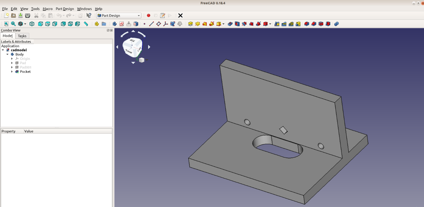
In this article we re-create our 3D printed loose tenon jig with FreeCAD as a tutorial for the Part Design workbench.
Jig modeling in FreeCAD’s part design workbench
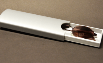
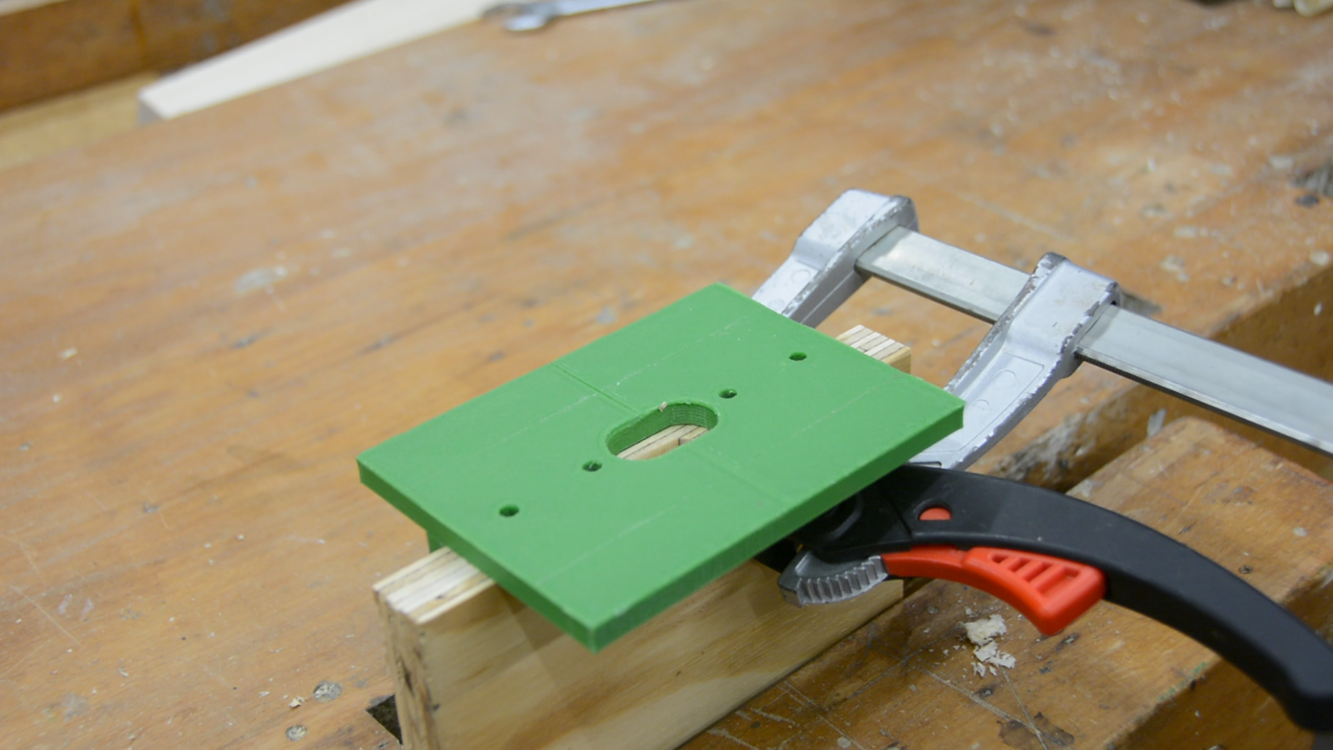
The original version of the jig was created in OpenScad and can be found on Thingiverse. It is a fairly simple design and we will use version 0.18 of FreeCAD to model it. If you only want to use the jig we leave a link to the original video in the description. This video is more about FreeCAD usage and less about the jig itself.
In the last tutorial we used the Part workbench to add simple shapes. The Part Design workbench works by creating 2D sketches and transforming them into 3D
shapes.
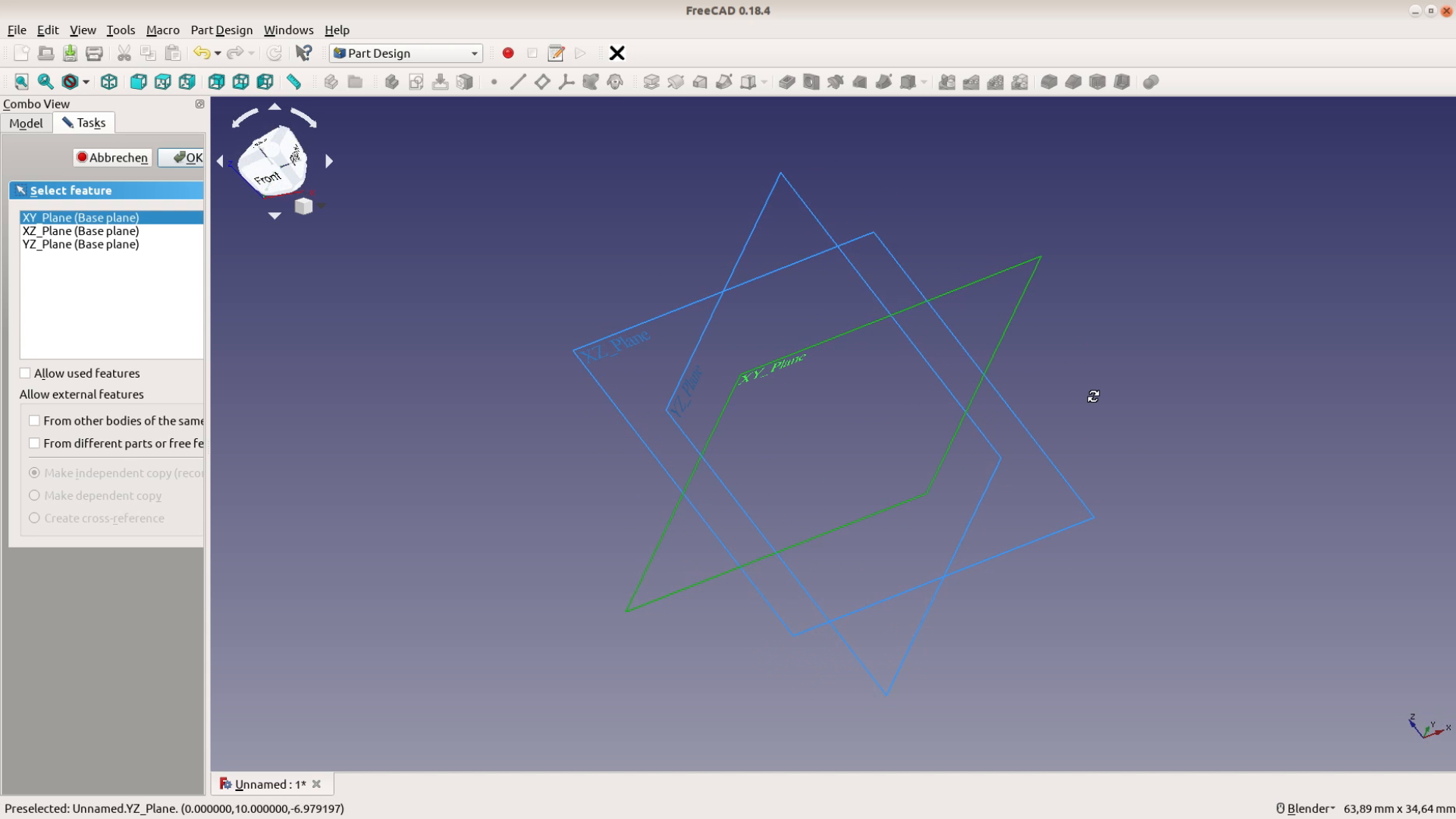
The first thing we need to do is to create a new body. Within this body we then create a sketch in the XY plane.
In the Sketcher we start with a rectangle that should be the base plate of the router jig. We just put the corners of the rectangle at arbitrary positions.
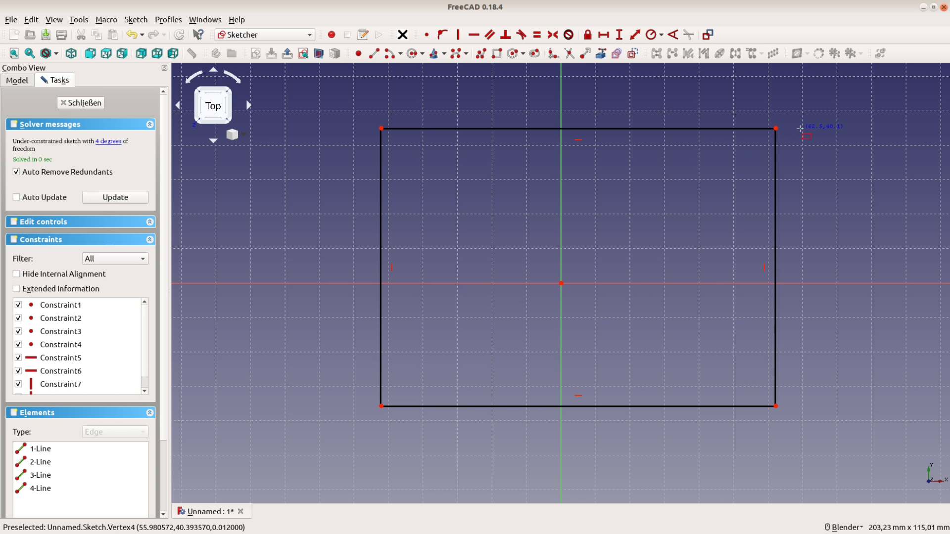
FreeCAD’s Part Design workbench is working with a constraint based system. This means that we have to first create our shapes and then restrict them. First we want to constraint the position of our rectangle. We select the two outer points and then the center. We apply a constraint with one of the buttons on the top. Here we center the two outer dots around the center. Let’s add some more constraints. We first select a horizontal constraint and set the width of the platform to 100 mm. In the same way we use a vertical measurement to set the height to 80 mm.

The sketch turns green – which shows that there is nothing left for us that we could change.
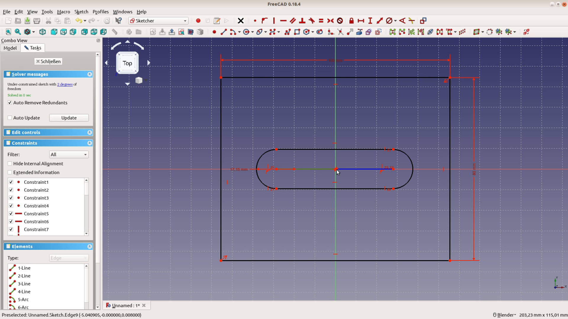
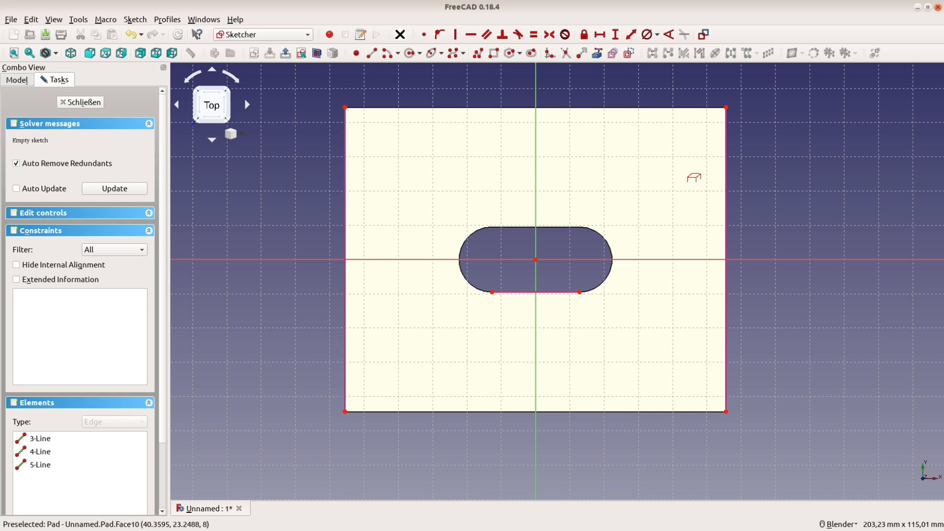
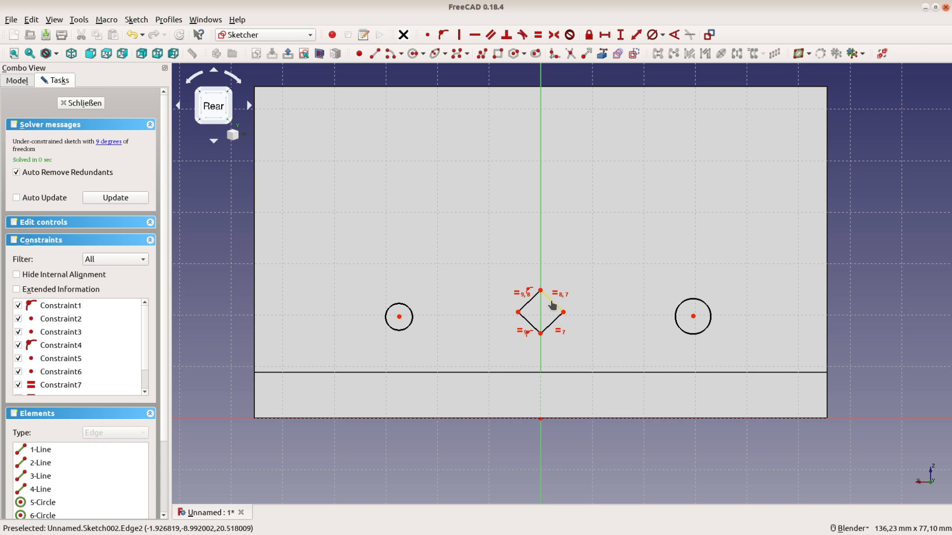
The sketch is fully constraint. Next we add the slot in the middle – which is going to guide our guide bushing. We add two half circles and connect them by lines.
By hovering over the line so that it turns yellow we automatically constrain the mid point of the circle to the horizontal line through the origin.
As it is possible to move the slot the sketch is no longer fully constraint and therefore no longer green.
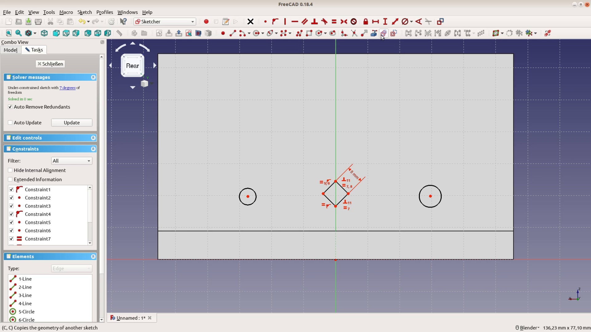
The half circles should have the same diameter – which is a bit over the diameter of the bushing.

Each half circle should cover 180 degrees so we constraint the three dots to be on one vertical line.

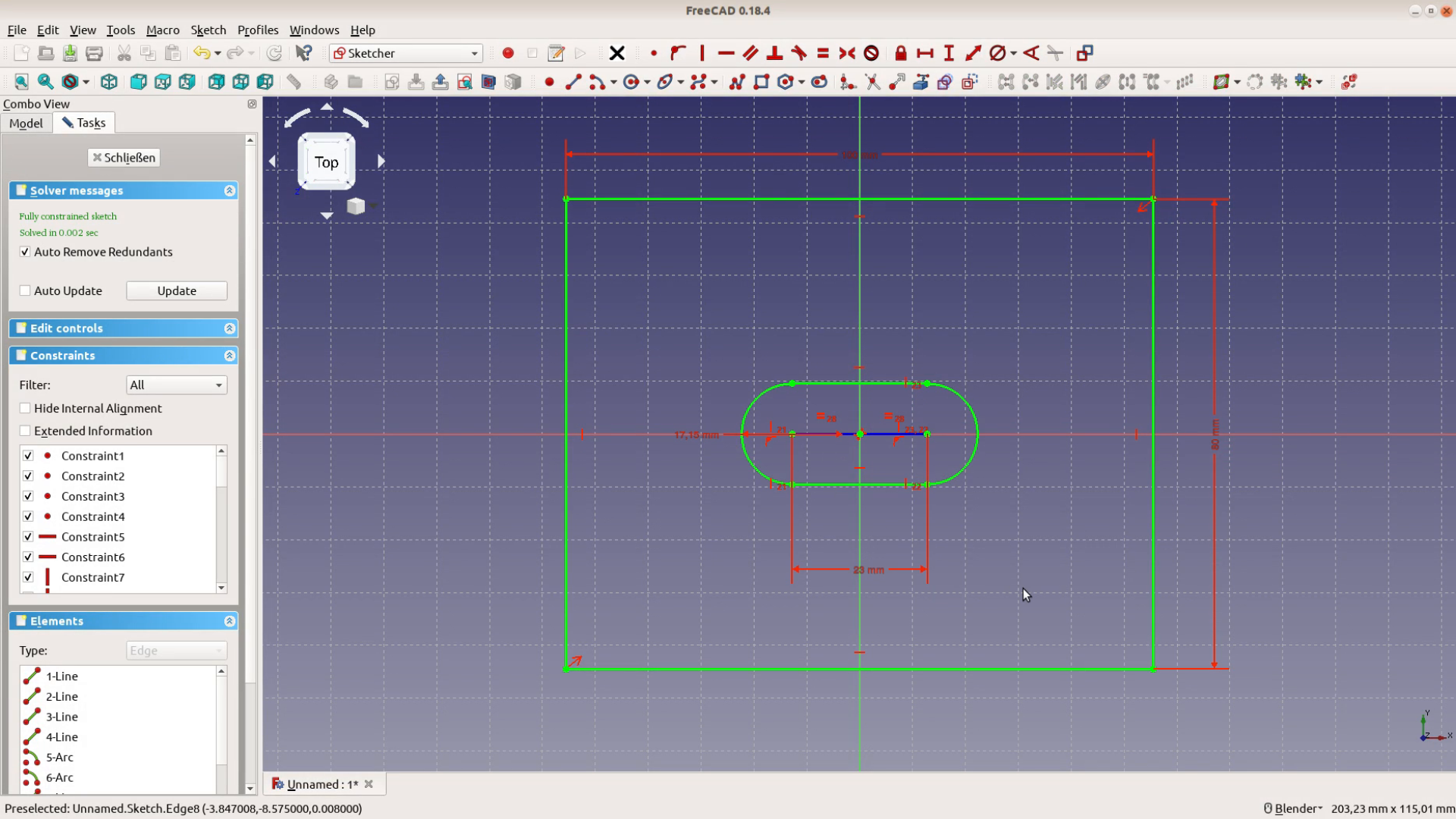
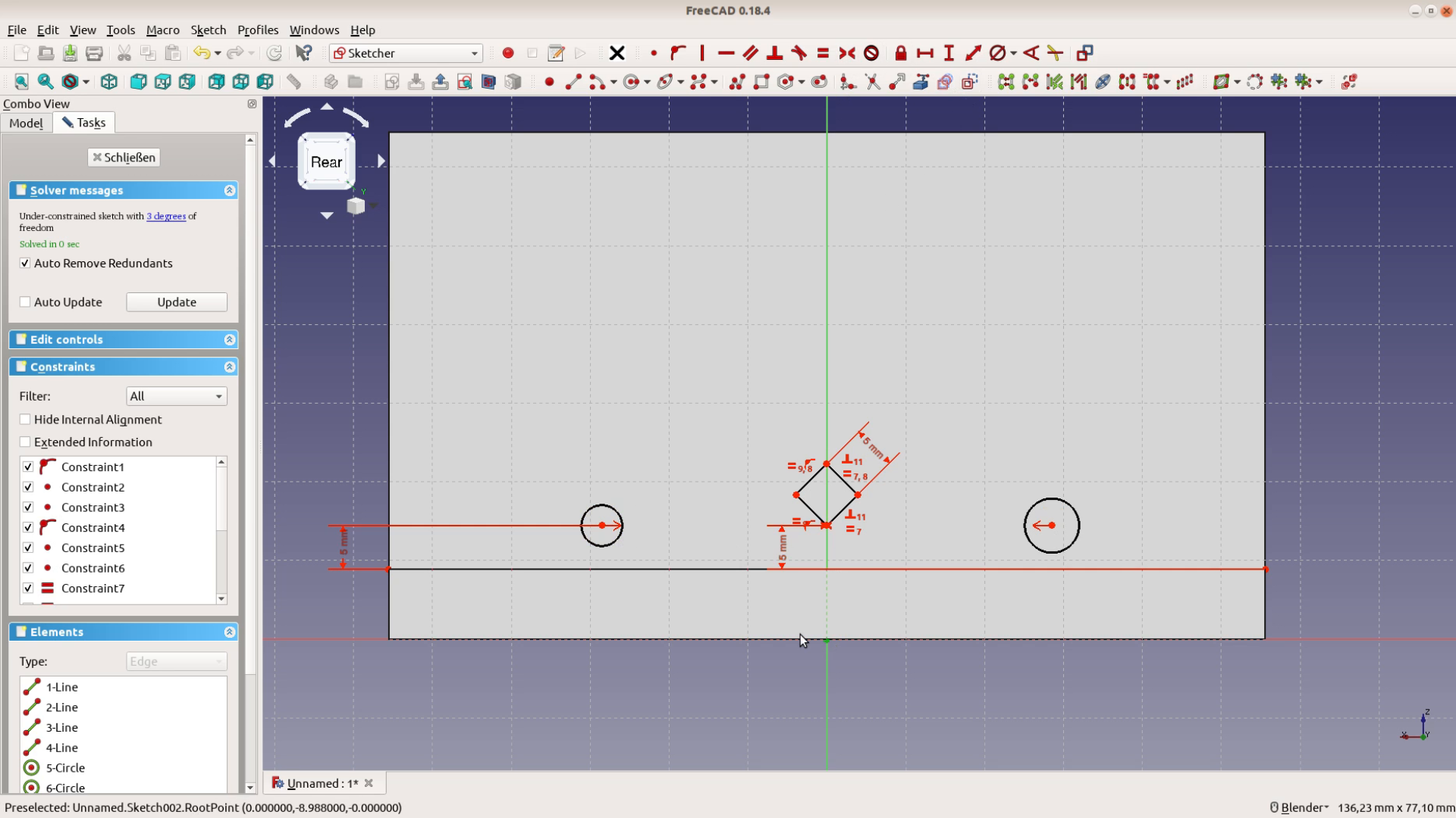
We could center the circles as we did before with the rectangle but let’s introduce a new feature. With the button with the dotted line we can switch from normal to construction lines. All the drawing tools turn blue. We connect the origin with the two centers with construction lines. By making them of equal length we centered the slot.
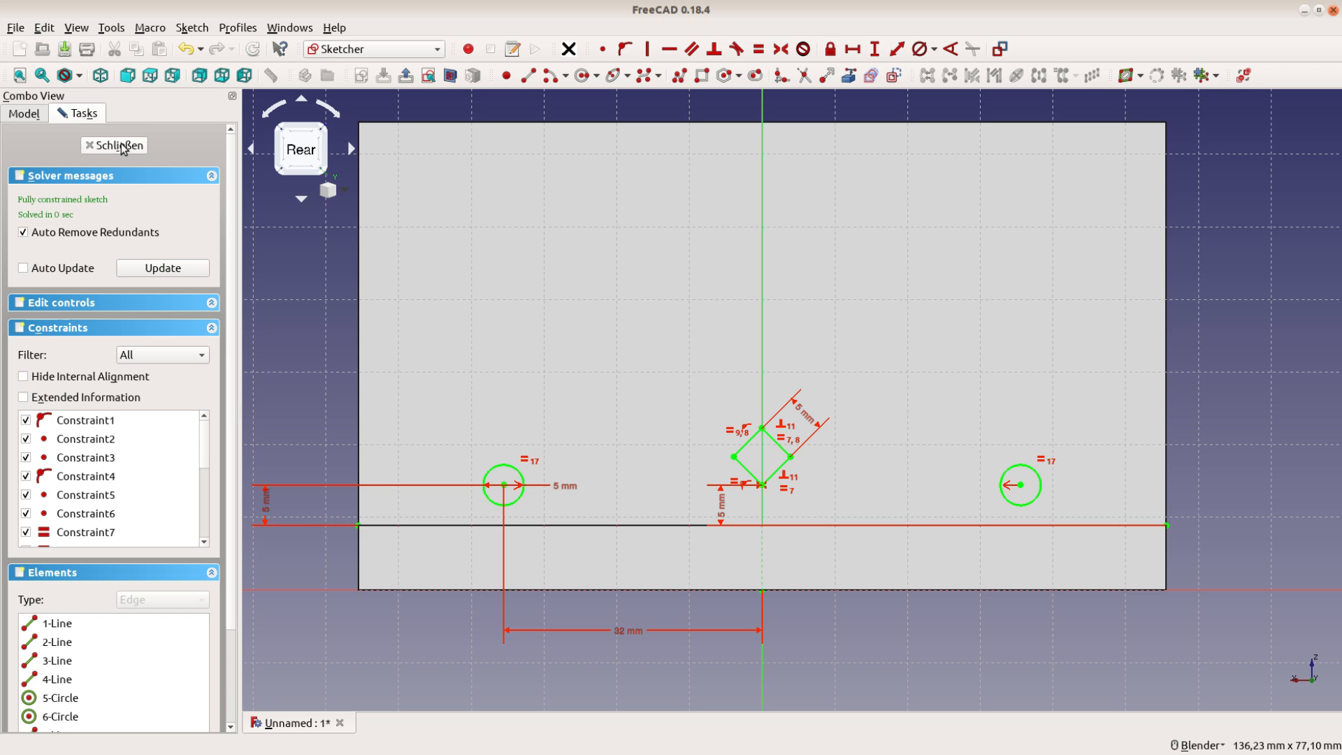
We then set the distance of the two circle centers and are done with the base plate. The sketch is fully constrained.
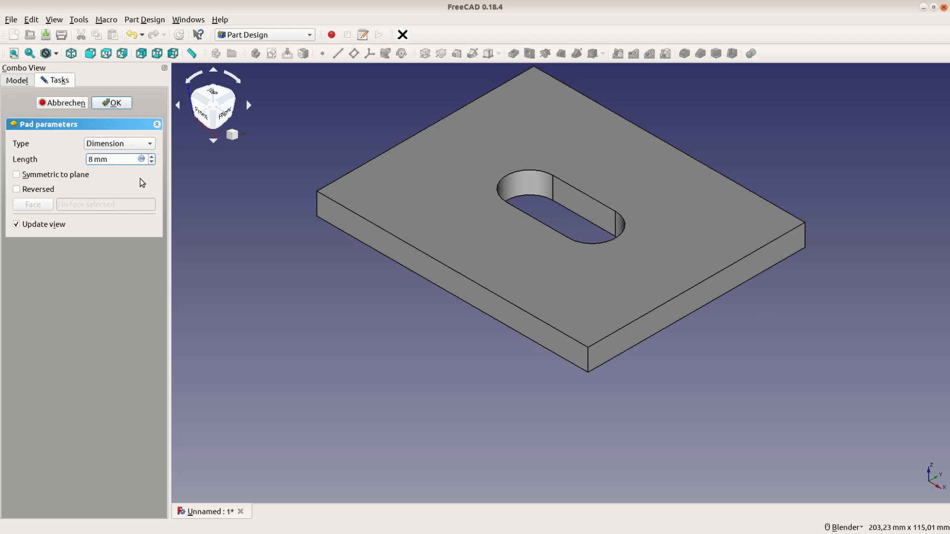
After closing the sketch the panel the FreeCAD Part Design Workbench on the left shows different options what we could do with the shape. In our case we want to extrude the shape. The pad tool extrudes the 2d shape to a 8 mm thick plate.
Adding elements
We select the upper face and select sketch on face from the task panel. With this icon we can use a line from another part as a reference. Let’s use two lines from the outer perimeter and one line from the slot.
This rectangle should become the supporting structure. When creating the rectangle we hover over the outer lines and thereby contrain the rectangle. The thickness of the plate is 8 mm and it is 9 mm away from the centerline of the slot.
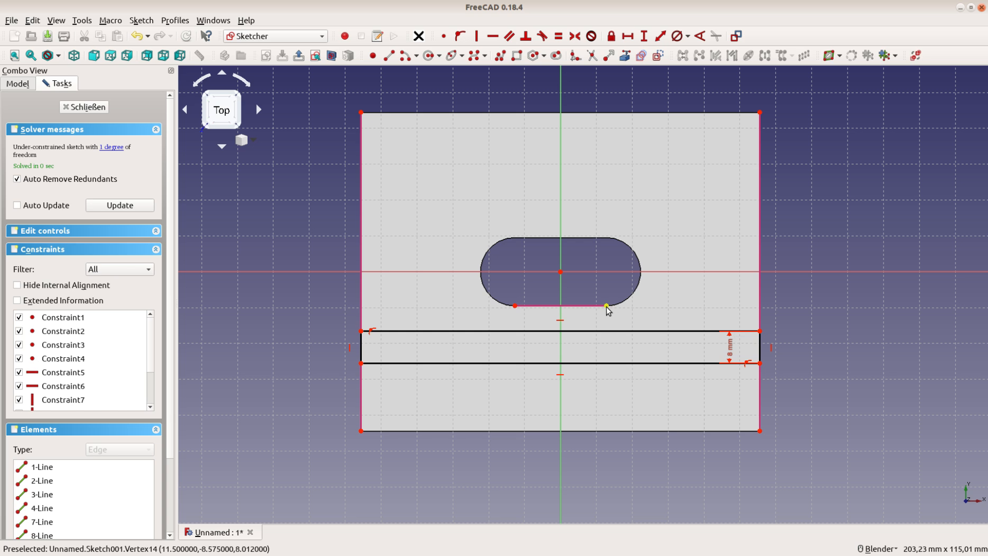
The sketch is fully constrained.
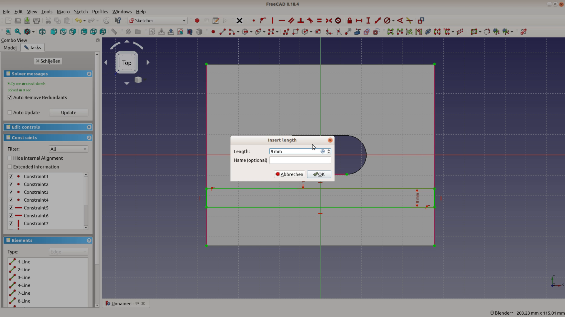
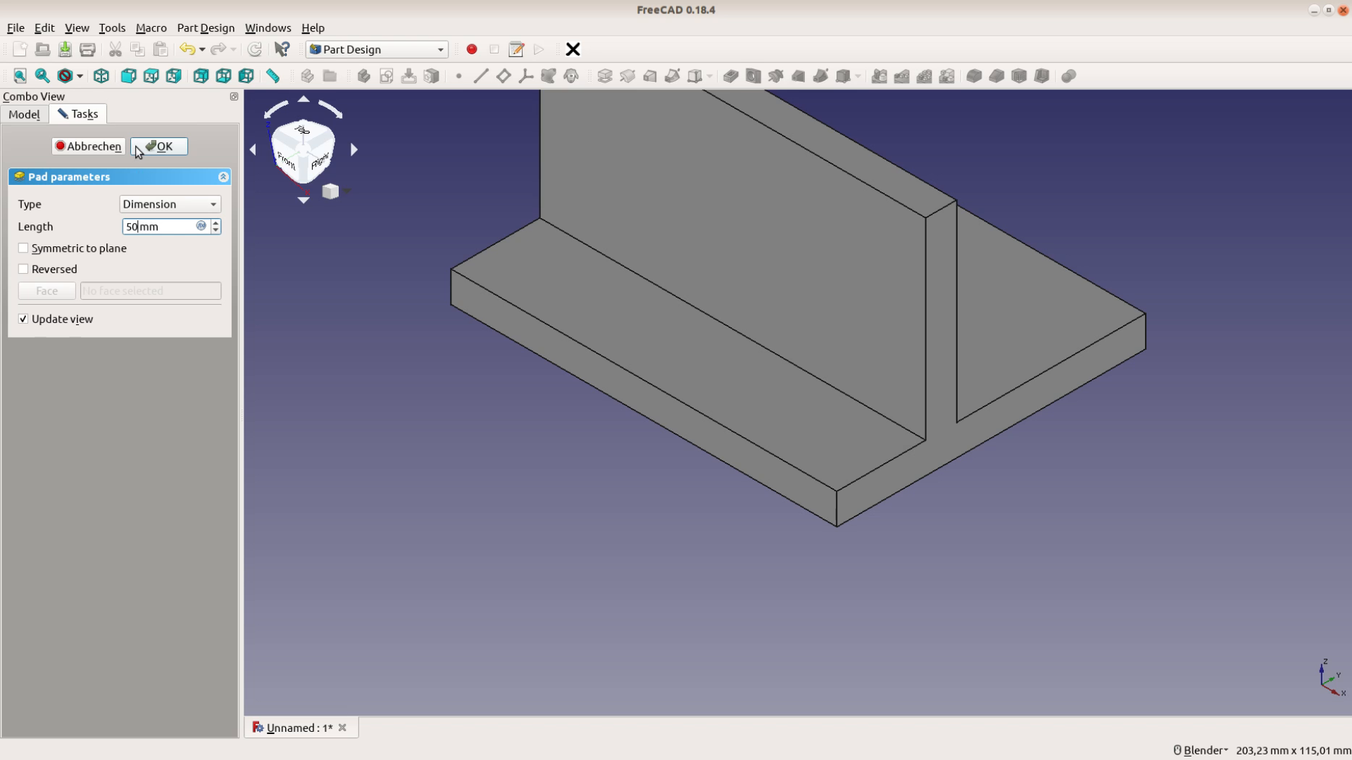
We can close the sketch and extrude it by 50 mm.
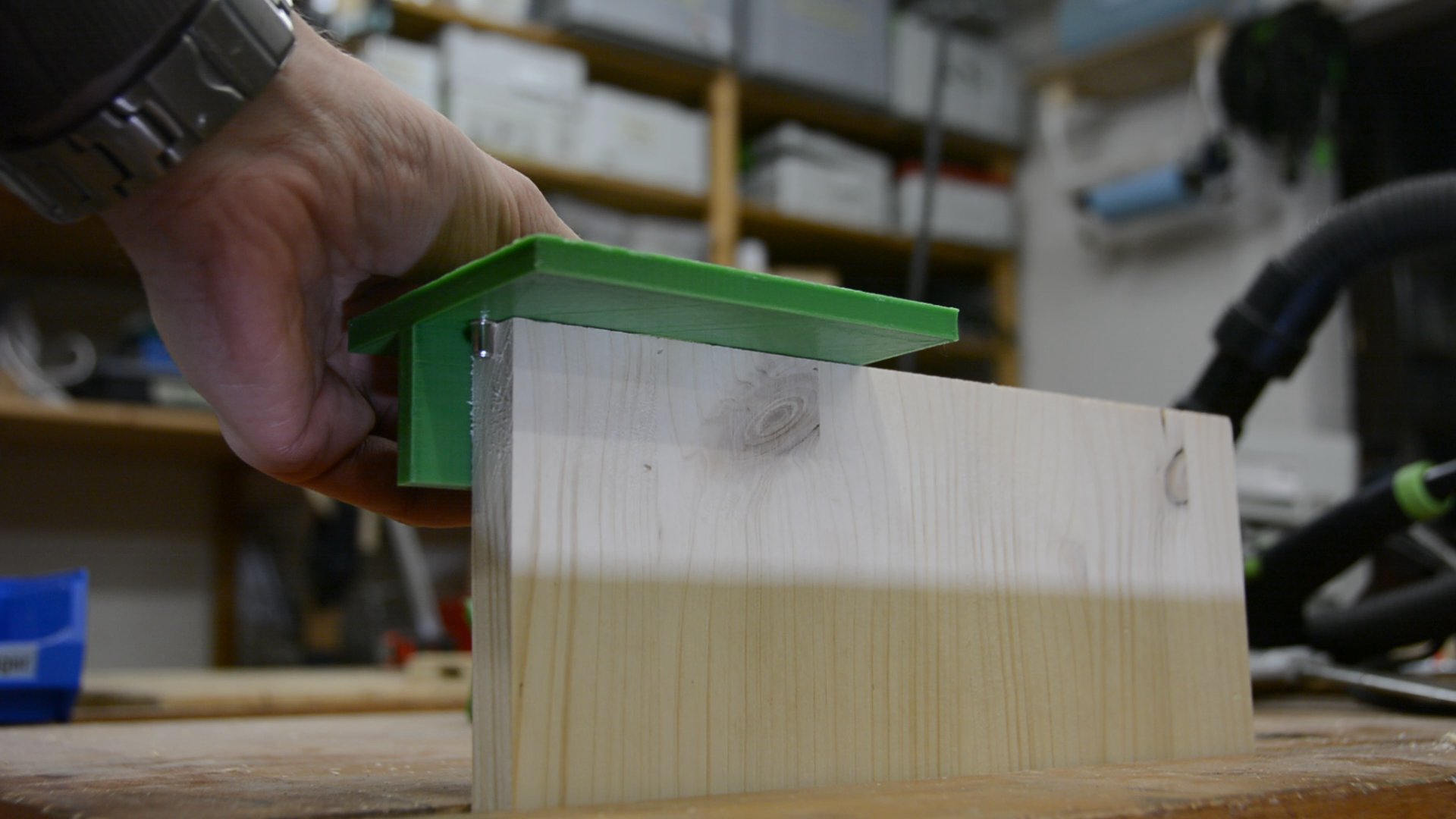
Adding alignment elements
Lastly we need a way to align the jig on the workpiece. As before we create a sketch on the newly created surface. For centering the jig on a pencil mark we have to create a square rotated by 90 degree.


These lines don’t look very square yet. The two opposing lines should be parallel and all the 4 lines should be of equal length.
The length of the sides is 5 mm and perpendicular to one another.
The square should be placed 5 mm above the bottom. For this we get the bottom line as an external reference and add a vertical measurement.

The two circles for alignment pins are now positioned 5 mm above the bottom. The centers should be on the same height and centered to the z axis. The distance between the center and the alignment pin is 32 mm.
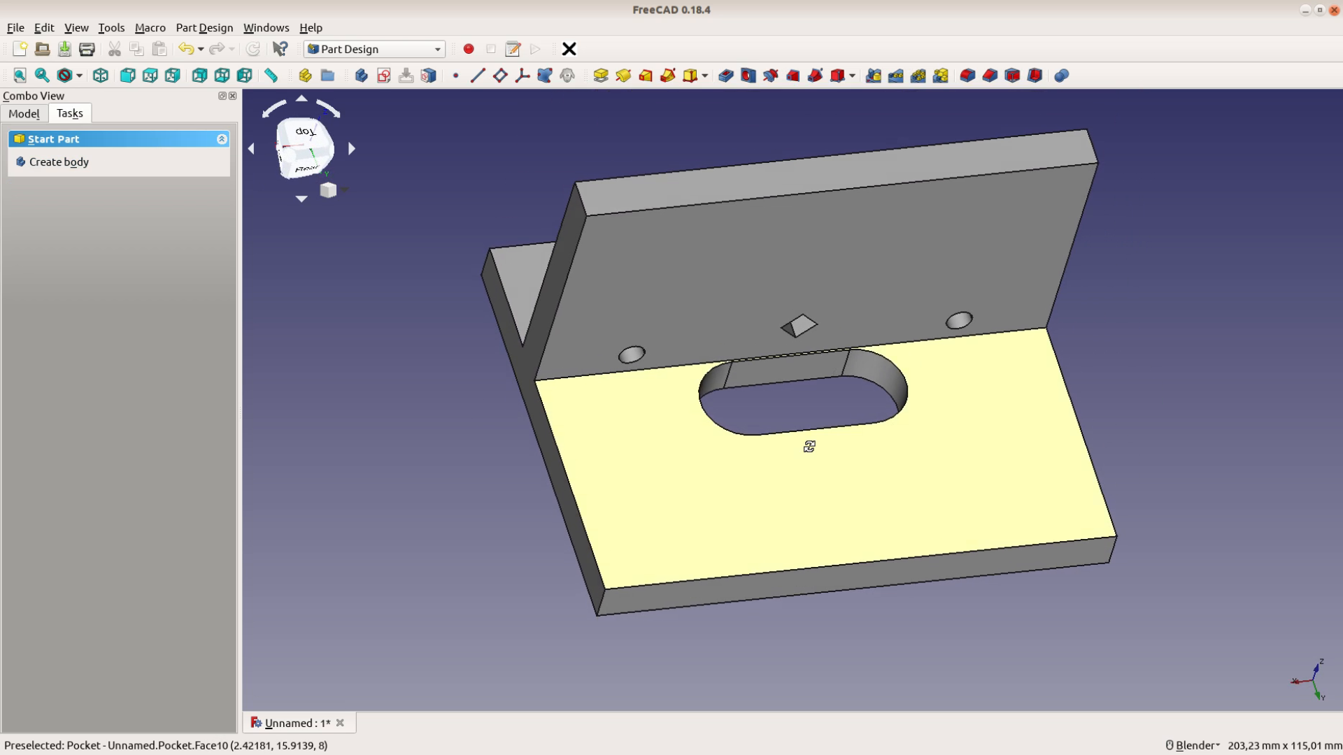
After closing the sketch we pocket these structures through the entire jig and have a perfectly usable domino jig.