Today we use the FreeCAD in a woodworking project. In the first part of this tutorial we use the part workbench to create 3d printed benchdogs.
This tutorial it the first of a multipart series on how to use FreeCAD in woodworking. It is not one of our normal build articles but focused on using FreeCAD step by step. In order to create something useful we will create a very simple Benchdog that you can 3d print and use for your workbench.
Getting started
We have an overview article on what‘s possible in woodworking when using FreeCAD. Here we start with some basic concepts.
We are working with FreeCAD version 0.19 in this tutorial. A very important concept of FreeCAD are workbenches. Think of these as the ribbons in Microsoft office. They are covering specific aspects of the 3d modeling workflow. In this tutorial we want to focus on the part workbench.
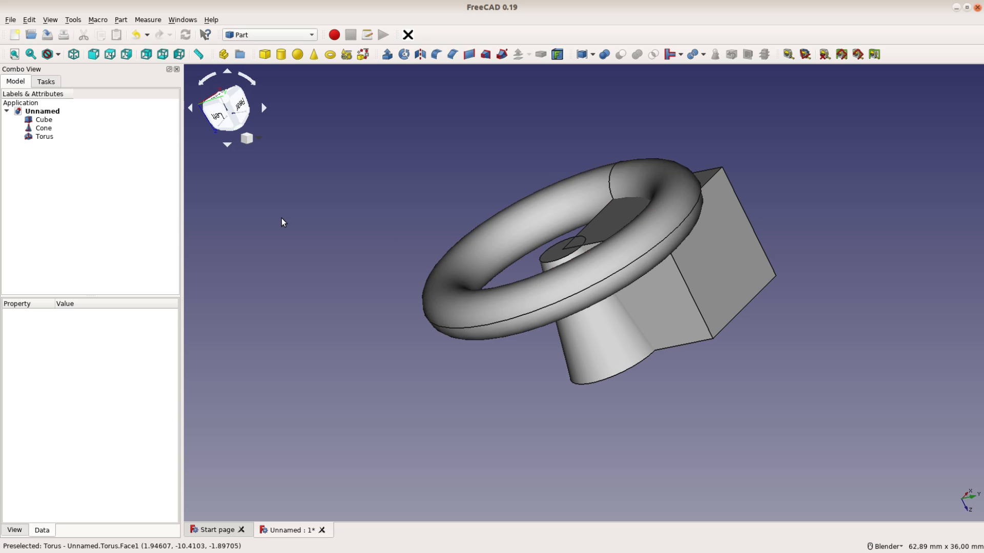
The part workbench is used to add simple shapes such as cubes, cones or a torus.
We delete a part by either selecting it in the main window or in the model tree on the left hand side and then pressing the delete key. For hiding a part select it and press space. We can unhide it with space again.
Woodworking benchdogs in FreeCAD
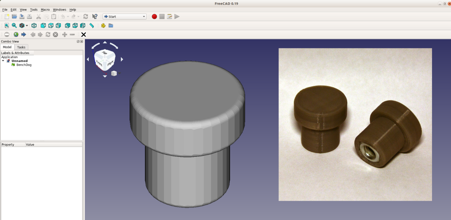
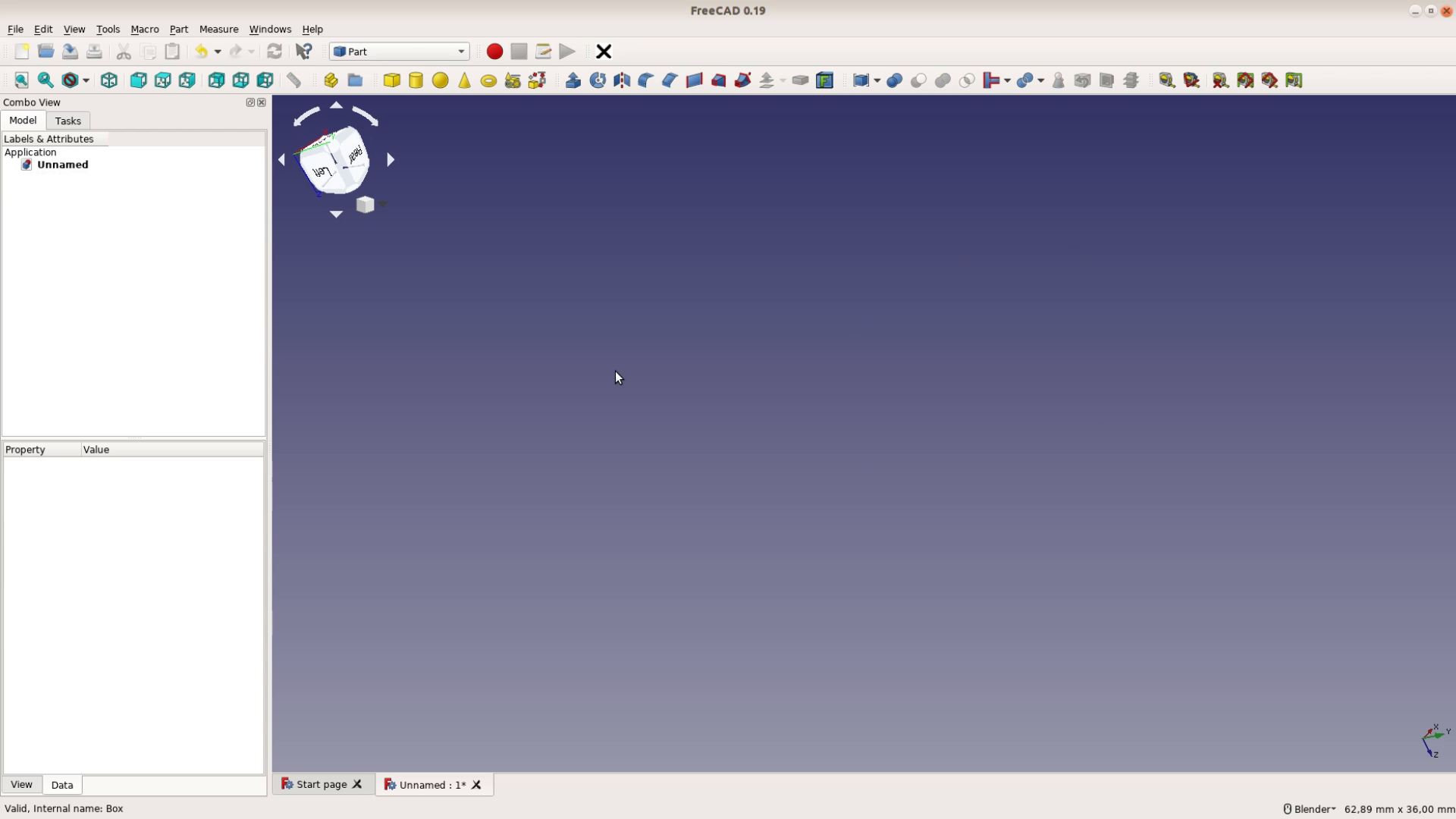
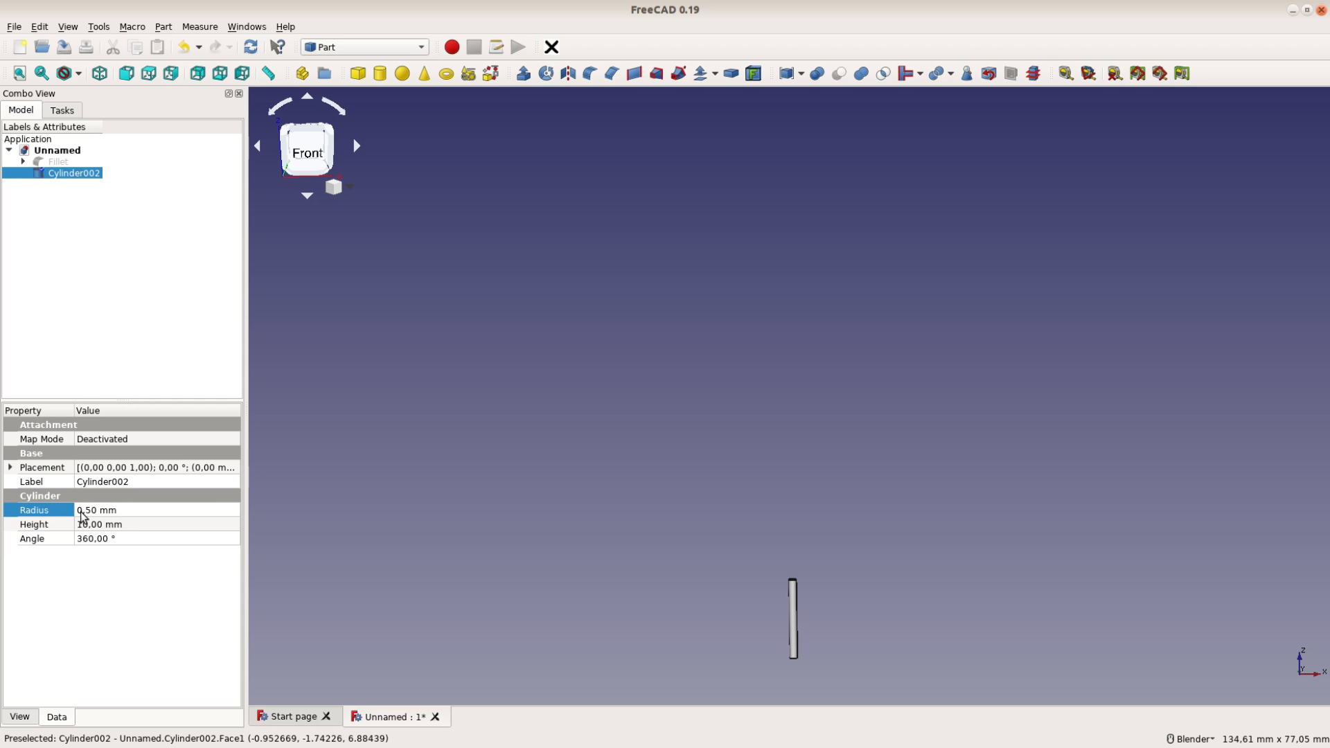
We want to model a benchdog that can be used with a MFT table or any other table with 20 mm holes. The part that goes into to hole is a cylinder.
After adding the cylinder we have to change its size. In the lower left corner we have a window that shows all the Data related to the selected object. The diameter of the cylinder should be 19.85 mm. As the input field expects a radius we type 19.85 divided by two and FreeCAD does the math for us. The height of the cylinder should be 27 mm.

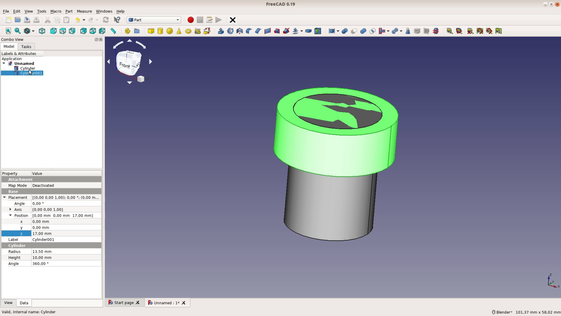
We add another cylinder for the upper part. We can see the new cylinder from below or by hiding the first one with space. This cylinder is 27 mm in diameter and the height of 10 mm is already correct. To move a part in FreeCAD we right click on the part and select transform. We can then move the part with one of the arrows.

A more precise way is to move a part in the placement section of the panel on the left. We increase the value of the z placement to 17.
Now we still have two parts. We combine these parts by selecting both of them and then use a Boolean union operation.
A super simple version of the benchdog could be done here. We want to take it one step further and add a M8 nut so that we can secure the benchdog from below the table.
Adding a nut to the benchdog
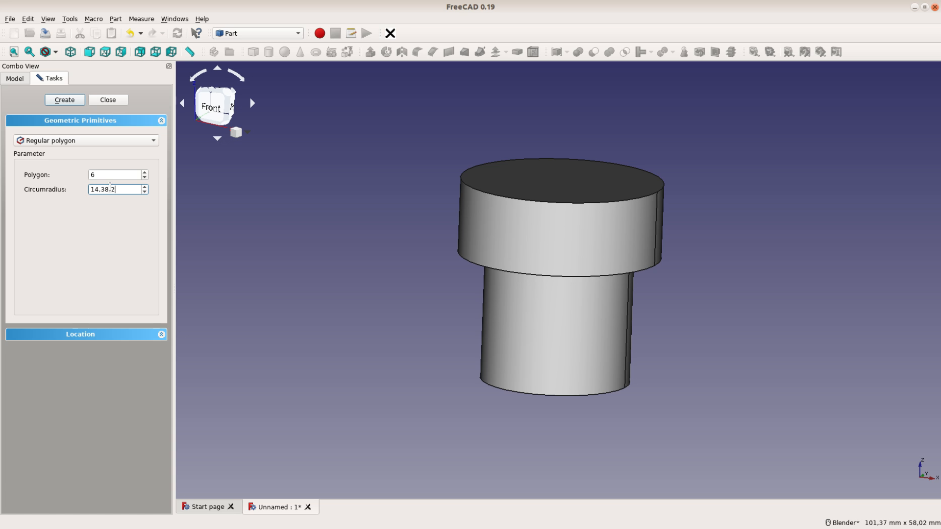
With this very crowded button we can add all kind of shapes. We use a polygon with the correct size for a M8 nut: A radius of 14.38 mm divided by
two. This polygon is a 2D shape that we have to extrude in order to get a solid. The thickness of a M8 nut is 6.5 mm.
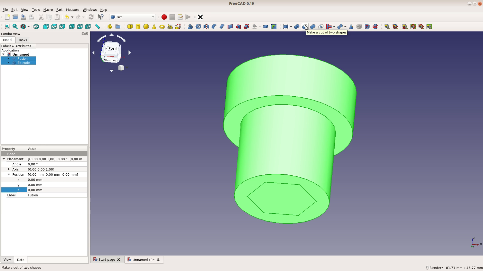
We use a cut operation to substract the nut from the benchdog.
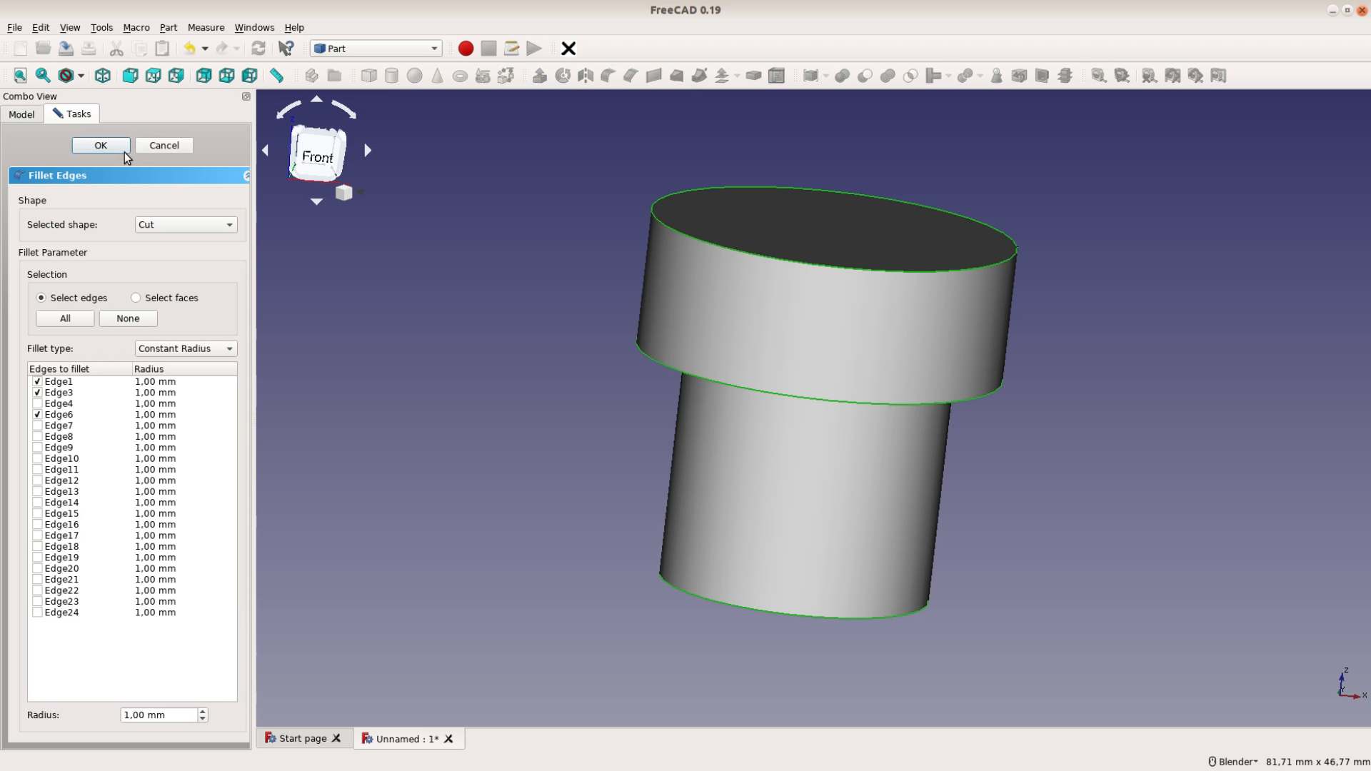
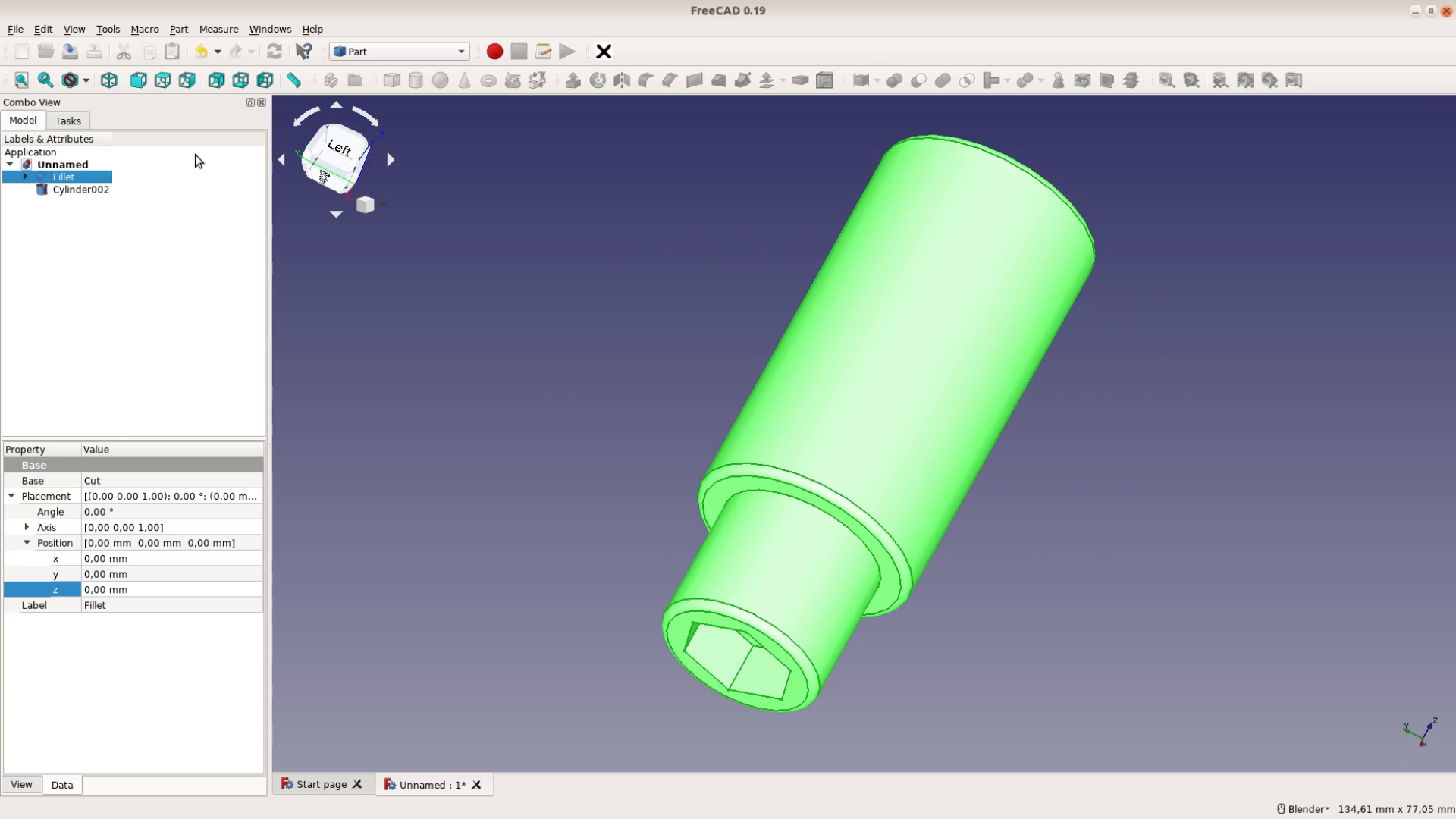
The corners are a bit too sharp for my taste. So let’s add a Filet operation. We select the thee edges we want to round over and then select a round over of 1mm.
Parametric design in FreeCAD
So far this object could have been created with Sketchup as well. The power of FreeCAD – especially in woodworking – is that it is a completely parametric system.
On the left hand side we can unfold the tree that defines our object. We see all the operations that we did so far and we can change them.
We go back to the second cylinder and increase its size so that we can push two boards or a track saw guide on top of the board against the benchdog. By changing the size in a parametric model we don’t have to repeat any of the other operations.
After changing parameters you have to mark the object for recompute and recompute the model with the button with the two arrows.

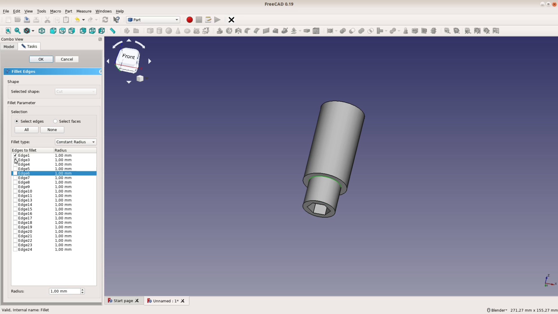
Only our fillet operation is messed up but we can easily fix this. A double click on the fillet brings up the task panel and we can select to correct edges for the round over.
If we 3D print the benchdogs with infill the lower part of the upper cylinder is going to be a weak spot. To reinforce this part we add a small cylinder and move it up and a little bit off center. Either by hiding the benchdog or with View, Clipping plane we can check where the cylinder is located.
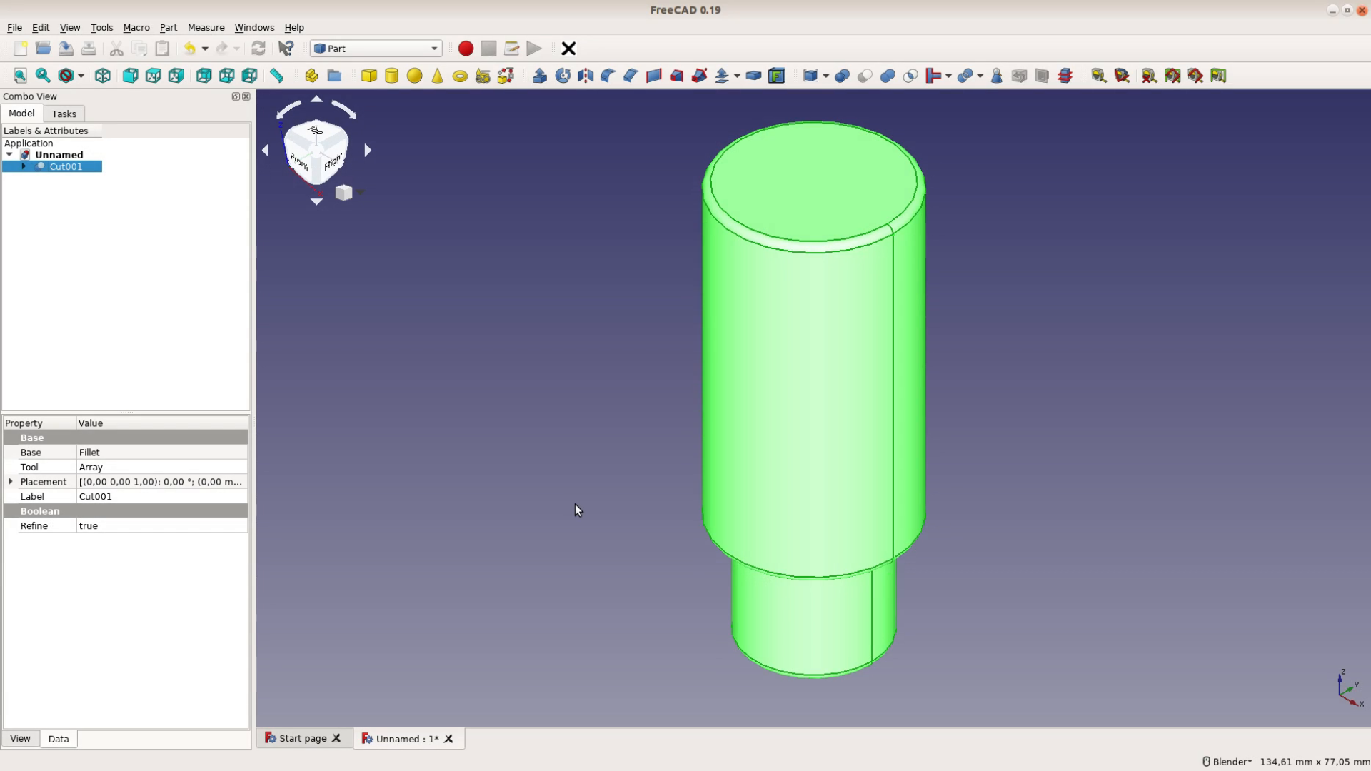
We position the small cylinder in the center of the seam. Now we switch to the Draft workbench and select the Array tool from the Draft menu.
We want to create multiple copies of this cylinder – which is a polar array and we decide to go with 10 copies. If we substract these small cylinders from the benchdog our slicer will later add additional walls around these internal tubes and thus reinforce the structure. We create again a clipping plane to check the position of the tubes.
To export the part select the top level part and export it with File, export and select STL as a file type.
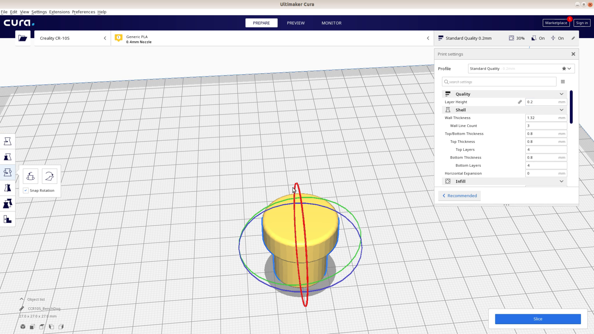
3D printing the benchdog
The STL can then be imported into Cura or any other slicer and printed.
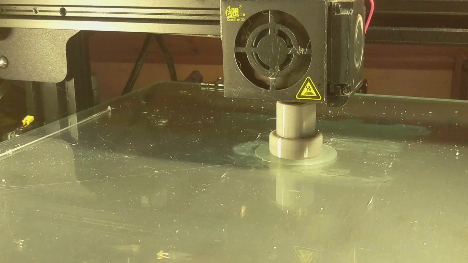
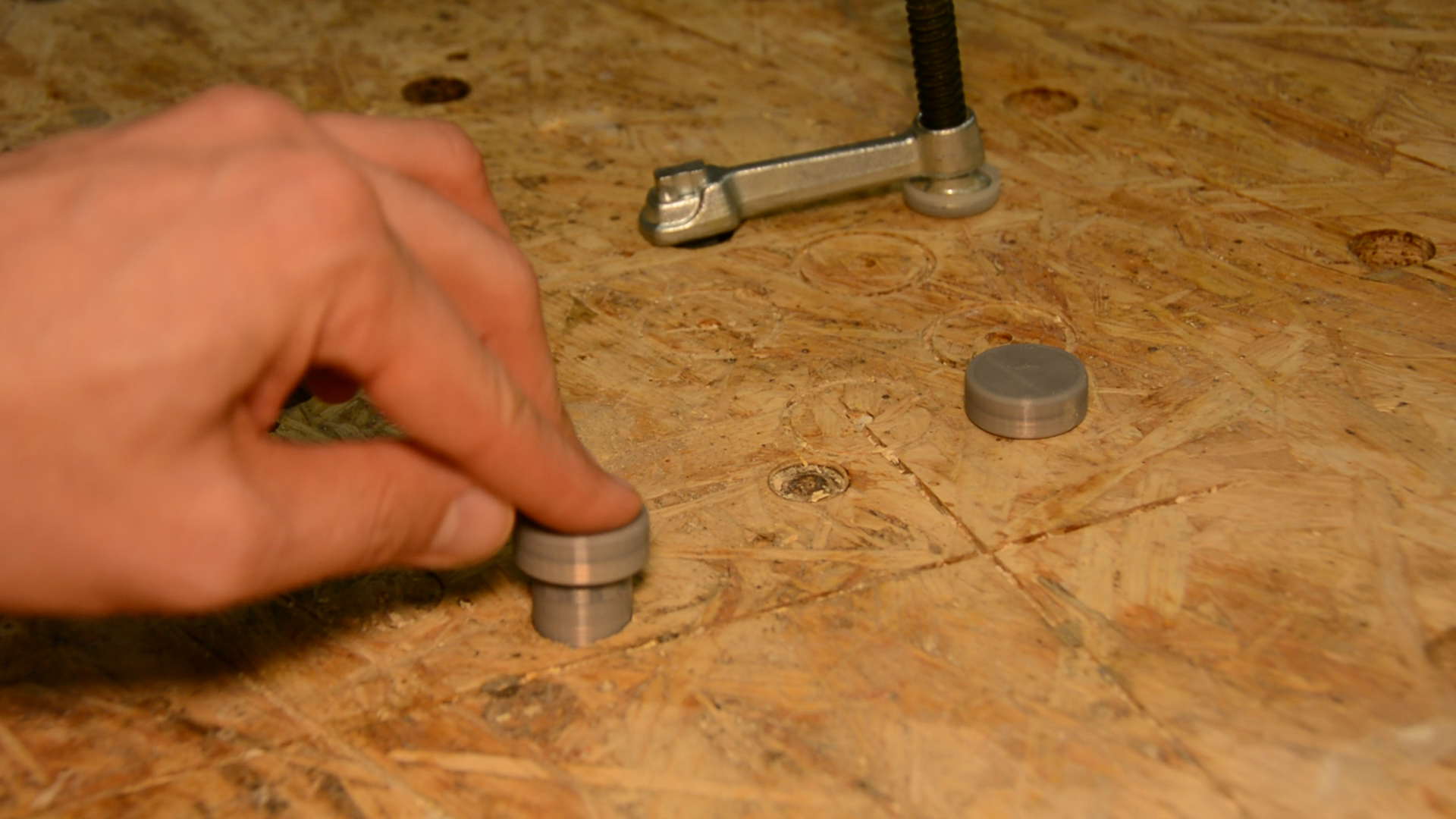
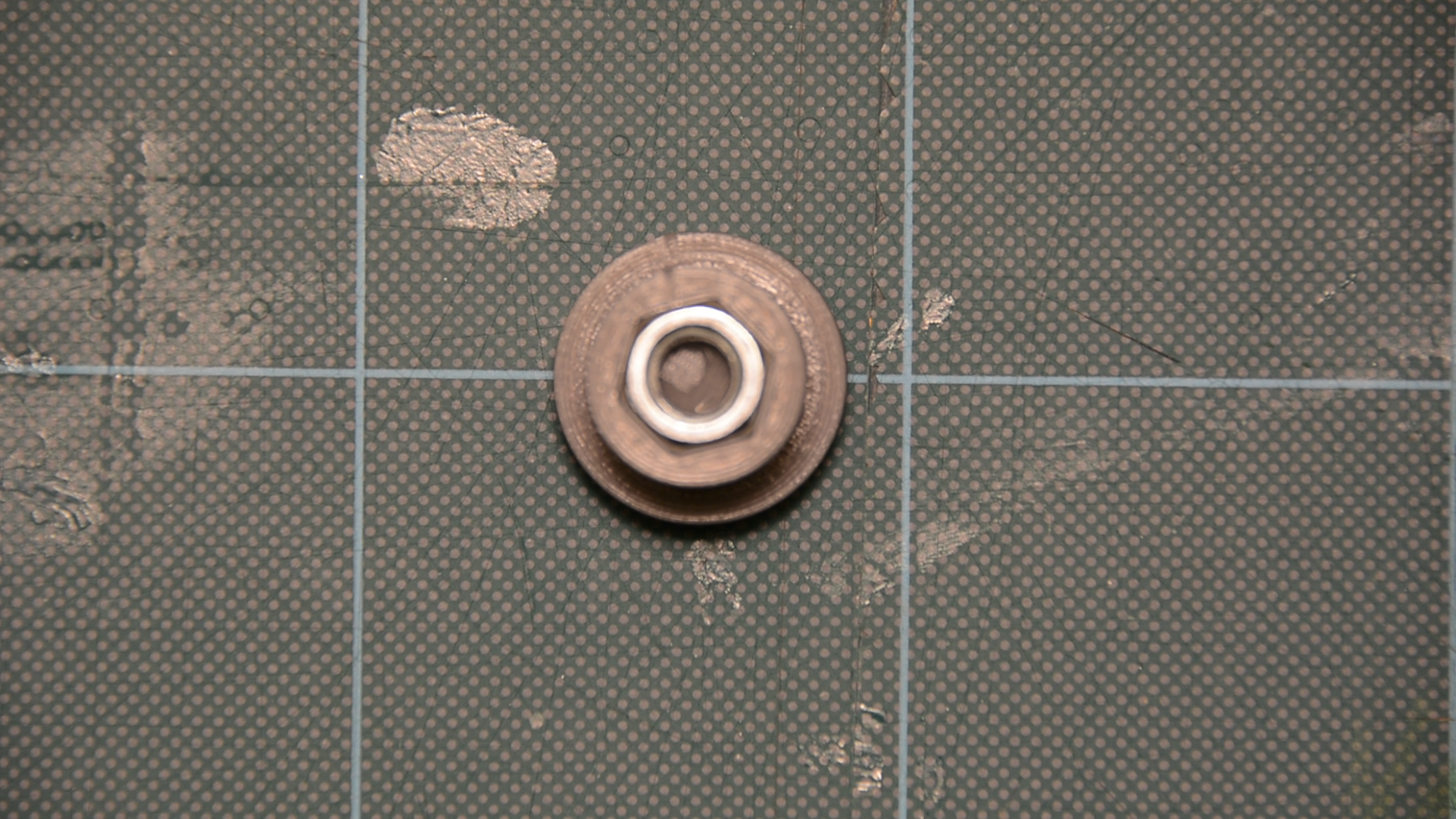
We then add a bit of superglue and press the M8 nut in place. We just completed our first FreeCAD woodworking project. The next part of the tutorial can be found here.
Resources